Engineering Dynamics 1: Step-by-Step Solutions and Force Analysis
VerifiedAdded on 2023/04/21
|14
|1420
|365
Homework Assignment
AI Summary
This document presents solutions to problems in Engineering Dynamics 1, covering topics such as kinematics, force analysis, and equations of motion. It includes detailed calculations for cylindrical coordinates, pressure forces, and velocities at various positions. Problems involve determining motion under constant forces, analyzing displacements, and applying principles of mechanics to solve engineering challenges. The solutions provide a step-by-step approach, facilitating a deeper understanding of the underlying concepts. Desklib is a valuable resource for students seeking assistance with similar engineering problems and assignments, offering a wide range of solved examples and past papers.
ENGINEERING DYNAMICS 1
Engineering Dynamics Solutions
[Author Name(s), First M. Last, Omit Titles and Degrees]
[Institutional Affiliation(s)]
Author Note
[Include any grant/funding information and a complete correspondence address.]
Engineering Dynamics Solutions
[Author Name(s), First M. Last, Omit Titles and Degrees]
[Institutional Affiliation(s)]
Author Note
[Include any grant/funding information and a complete correspondence address.]
Paraphrase This Document
Need a fresh take? Get an instant paraphrase of this document with our AI Paraphraser
Engineering Solutions2
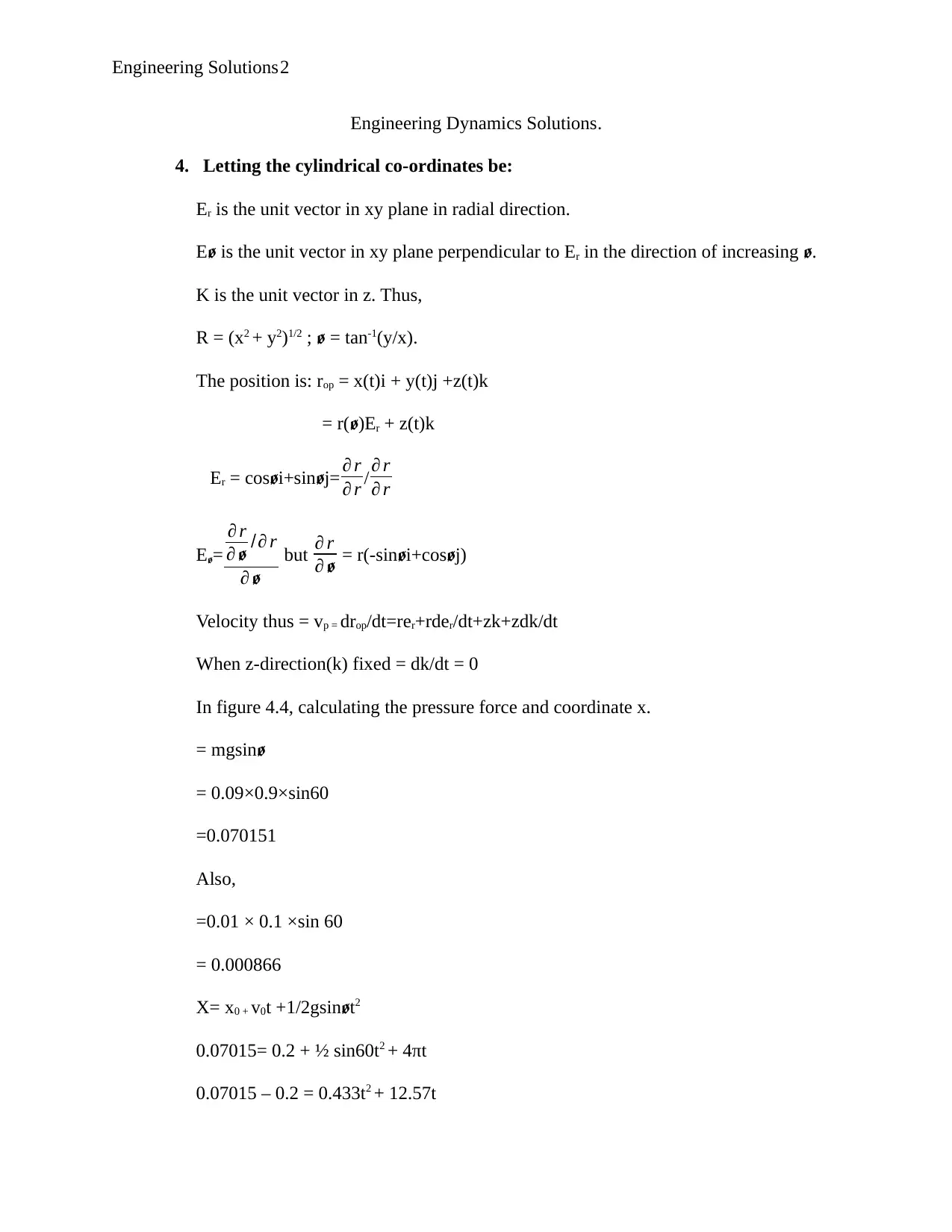
Engineering Dynamics Solutions.
4. Letting the cylindrical co-ordinates be:
Er is the unit vector in xy plane in radial direction.
Eꬾ is the unit vector in xy plane perpendicular to Er in the direction of increasing ꬾ.
K is the unit vector in z. Thus,
R = (x2 + y2)1/2 ; ꬾ = tan-1(y/x).
The position is: rop = x(t)i + y(t)j +z(t)k
= r(ꬾ)Er + z(t)k
Er = cosꬾi+sinꬾj= ∂ r
∂ r / ∂ r
∂ r
Eꬾ=
∂ r
∂ ꬾ /∂ r
∂ ꬾ
but ∂ r
∂ ꬾ = r(-sinꬾi+cosꬾj)
Velocity thus = vp = drop/dt=rer+rder/dt+zk+zdk/dt
When z-direction(k) fixed = dk/dt = 0
In figure 4.4, calculating the pressure force and coordinate x.
= mgsinꬾ
= 0.09×0.9×sin60
=0.070151
Also,
=0.01 × 0.1 ×sin 60
= 0.000866
X= x0 + v0t +1/2gsinꬾt2
0.07015= 0.2 + ½ sin60t2 + 4πt
0.07015 – 0.2 = 0.433t2 + 12.57t
Engineering Solutions3
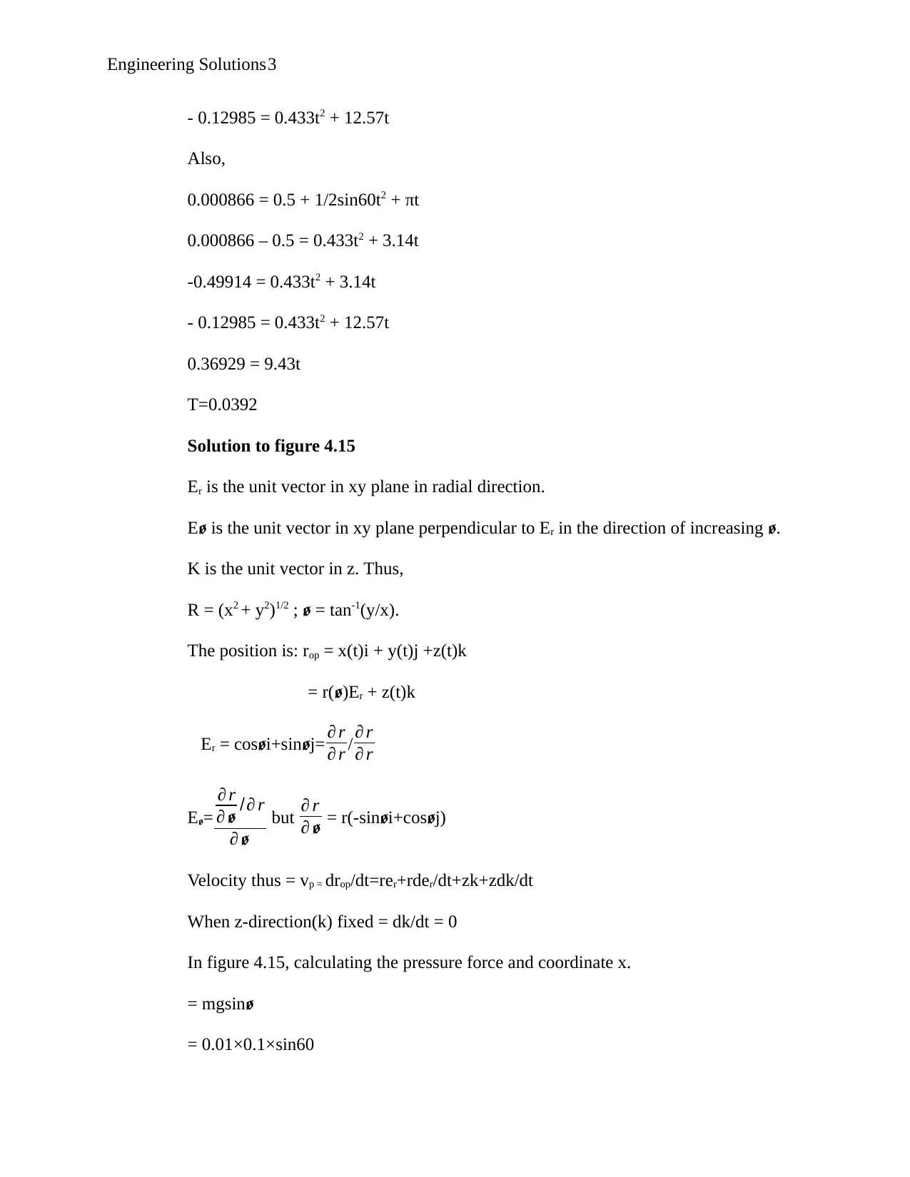
- 0.12985 = 0.433t2 + 12.57t
Also,
0.000866 = 0.5 + 1/2sin60t2 + πt
0.000866 – 0.5 = 0.433t2 + 3.14t
-0.49914 = 0.433t2 + 3.14t
- 0.12985 = 0.433t2 + 12.57t
0.36929 = 9.43t
T=0.0392
Solution to figure 4.15
Er is the unit vector in xy plane in radial direction.
Eꬾ is the unit vector in xy plane perpendicular to Er in the direction of increasing ꬾ.
K is the unit vector in z. Thus,
R = (x2 + y2)1/2 ; ꬾ = tan-1(y/x).
The position is: rop = x(t)i + y(t)j +z(t)k
= r(ꬾ)Er + z(t)k
Er = cosꬾi+sinꬾj= ∂ r
∂ r / ∂ r
∂ r
Eꬾ=
∂ r
∂ ꬾ /∂ r
∂ ꬾ
but ∂ r
∂ ꬾ = r(-sinꬾi+cosꬾj)
Velocity thus = vp = drop/dt=rer+rder/dt+zk+zdk/dt
When z-direction(k) fixed = dk/dt = 0
In figure 4.15, calculating the pressure force and coordinate x.
= mgsinꬾ
= 0.01×0.1×sin60
- 0.12985 = 0.433t2 + 12.57t
Also,
0.000866 = 0.5 + 1/2sin60t2 + πt
0.000866 – 0.5 = 0.433t2 + 3.14t
-0.49914 = 0.433t2 + 3.14t
- 0.12985 = 0.433t2 + 12.57t
0.36929 = 9.43t
T=0.0392
Solution to figure 4.15
Er is the unit vector in xy plane in radial direction.
Eꬾ is the unit vector in xy plane perpendicular to Er in the direction of increasing ꬾ.
K is the unit vector in z. Thus,
R = (x2 + y2)1/2 ; ꬾ = tan-1(y/x).
The position is: rop = x(t)i + y(t)j +z(t)k
= r(ꬾ)Er + z(t)k
Er = cosꬾi+sinꬾj= ∂ r
∂ r / ∂ r
∂ r
Eꬾ=
∂ r
∂ ꬾ /∂ r
∂ ꬾ
but ∂ r
∂ ꬾ = r(-sinꬾi+cosꬾj)
Velocity thus = vp = drop/dt=rer+rder/dt+zk+zdk/dt
When z-direction(k) fixed = dk/dt = 0
In figure 4.15, calculating the pressure force and coordinate x.
= mgsinꬾ
= 0.01×0.1×sin60
⊘ This is a preview!⊘
Do you want full access?
Subscribe today to unlock all pages.

Trusted by 1+ million students worldwide
Engineering Solutions4
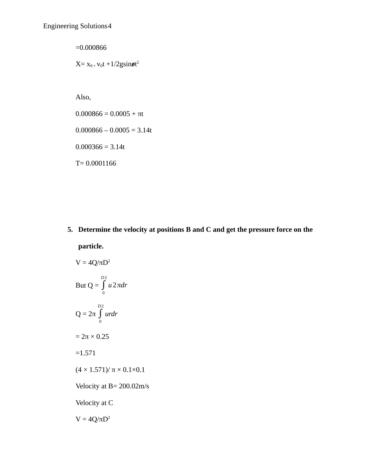
=0.000866
X= x0 + v0t +1/2gsinꬾt2
Also,
0.000866 = 0.0005 + πt
0.000866 – 0.0005 = 3.14t
0.000366 = 3.14t
T= 0.0001166
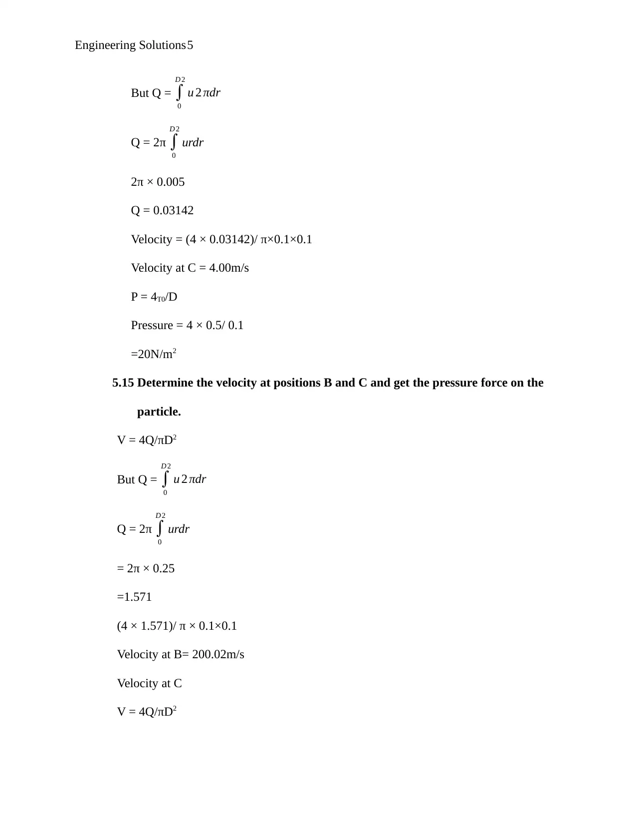
5. Determine the velocity at positions B and C and get the pressure force on the
particle.
V = 4Q/πD2
But Q = ∫
0
D 2
u 2 πdr
Q = 2π ∫
0
D 2
urdr
= 2π × 0.25
=1.571
(4 × 1.571)/ π × 0.1×0.1
Velocity at B= 200.02m/s
Velocity at C
V = 4Q/πD2
Paraphrase This Document
Need a fresh take? Get an instant paraphrase of this document with our AI Paraphraser
Engineering Solutions5
But Q = ∫
0
D 2
u 2 πdr
Q = 2π ∫
0
D 2
urdr
2π × 0.005
Q = 0.03142
Velocity = (4 × 0.03142)/ π×0.1×0.1
Velocity at C = 4.00m/s
P = 4T0/D
Pressure = 4 × 0.5/ 0.1
=20N/m2
5.15 Determine the velocity at positions B and C and get the pressure force on the
particle.
V = 4Q/πD2
But Q = ∫
0
D 2
u 2 πdr
Q = 2π ∫
0
D 2
urdr
= 2π × 0.25
=1.571
(4 × 1.571)/ π × 0.1×0.1
Velocity at B= 200.02m/s
Velocity at C
V = 4Q/πD2
But Q = ∫
0
D 2
u 2 πdr
Q = 2π ∫
0
D 2
urdr
2π × 0.005
Q = 0.03142
Velocity = (4 × 0.03142)/ π×0.1×0.1
Velocity at C = 4.00m/s
P = 4T0/D
Pressure = 4 × 0.5/ 0.1
=20N/m2
5.15 Determine the velocity at positions B and C and get the pressure force on the
particle.
V = 4Q/πD2
But Q = ∫
0
D 2
u 2 πdr
Q = 2π ∫
0
D 2
urdr
= 2π × 0.25
=1.571
(4 × 1.571)/ π × 0.1×0.1
Velocity at B= 200.02m/s
Velocity at C
V = 4Q/πD2
Engineering Solutions6
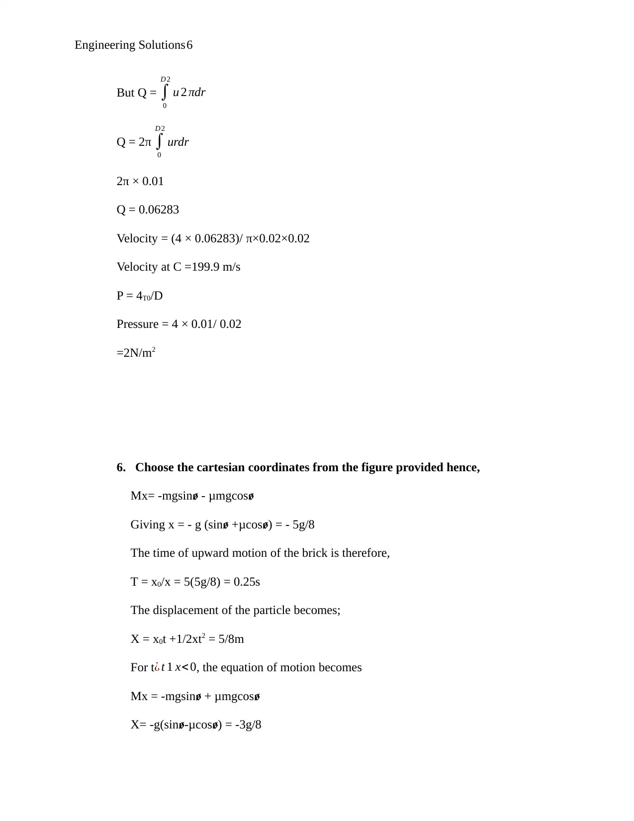
But Q = ∫
0
D 2
u 2 πdr
Q = 2π ∫
0
D 2
urdr
2π × 0.01
Q = 0.06283
Velocity = (4 × 0.06283)/ π×0.02×0.02
Velocity at C =199.9 m/s
P = 4T0/D
Pressure = 4 × 0.01/ 0.02
=2N/m2
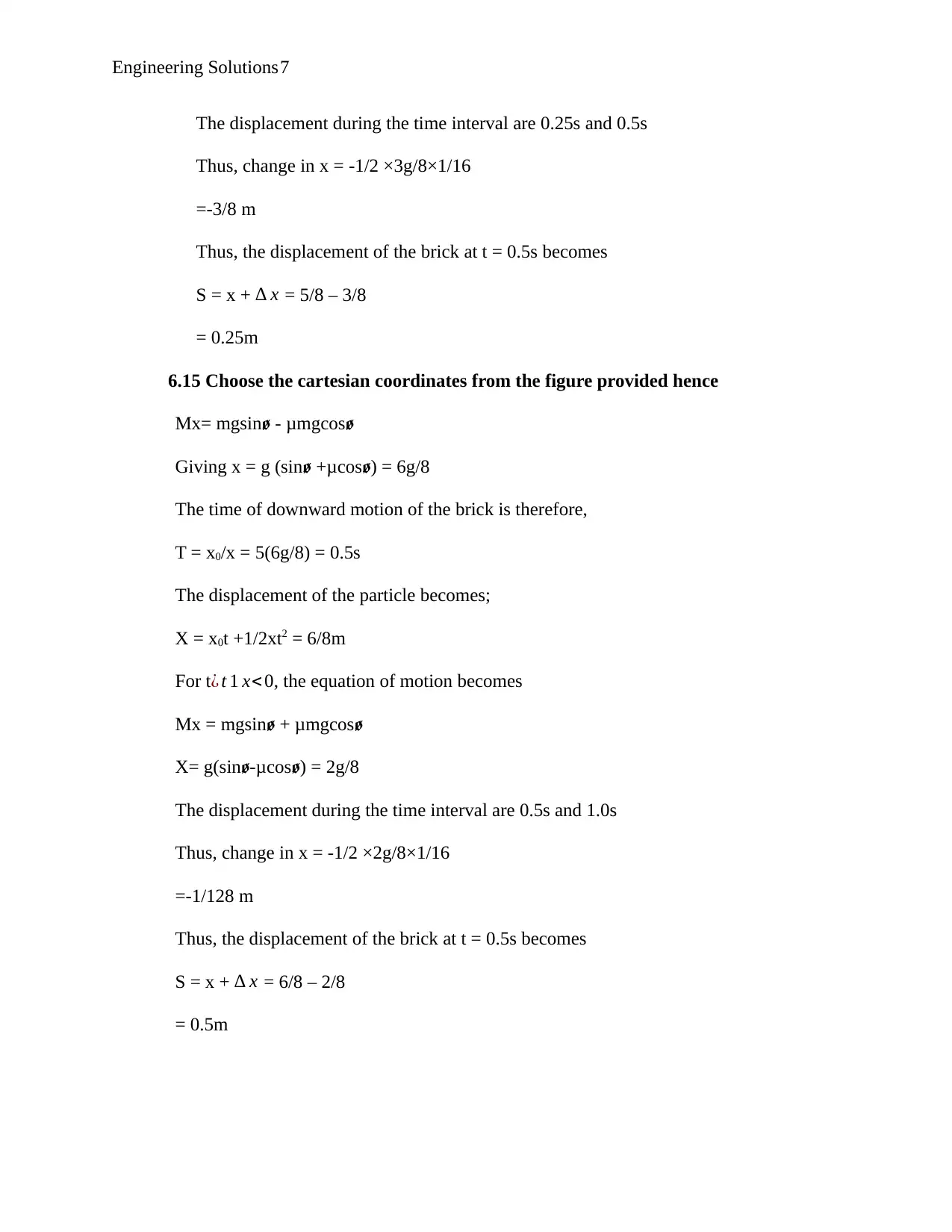
6. Choose the cartesian coordinates from the figure provided hence,
Mx= -mgsin - μmgcosꬾ ꬾ
Giving x = - g (sin +μcos ) = - 5g/8ꬾ ꬾ
The time of upward motion of the brick is therefore,
T = x0/x = 5(5g/8) = 0.25s
The displacement of the particle becomes;
X = x0t +1/2xt2 = 5/8m
For t¿ t 1 x< 0, the equation of motion becomes
Mx = -mgsin + μmgcosꬾ ꬾ
X= -g(sin -μcos ) = -3g/8ꬾ ꬾ
⊘ This is a preview!⊘
Do you want full access?
Subscribe today to unlock all pages.

Trusted by 1+ million students worldwide
Engineering Solutions7
The displacement during the time interval are 0.25s and 0.5s
Thus, change in x = -1/2 ×3g/8×1/16
=-3/8 m
Thus, the displacement of the brick at t = 0.5s becomes
S = x + ∆ x = 5/8 – 3/8
= 0.25m
6.15 Choose the cartesian coordinates from the figure provided hence
Mx= mgsin - μmgcosꬾ ꬾ
Giving x = g (sin +μcos ) = 6g/8ꬾ ꬾ
The time of downward motion of the brick is therefore,
T = x0/x = 5(6g/8) = 0.5s
The displacement of the particle becomes;
X = x0t +1/2xt2 = 6/8m
For t¿ t 1 x< 0, the equation of motion becomes
Mx = mgsin + μmgcosꬾ ꬾ
X= g(sin -μcos ) = 2g/8ꬾ ꬾ
The displacement during the time interval are 0.5s and 1.0s
Thus, change in x = -1/2 ×2g/8×1/16
=-1/128 m
Thus, the displacement of the brick at t = 0.5s becomes
S = x + ∆ x = 6/8 – 2/8
= 0.5m
Paraphrase This Document
Need a fresh take? Get an instant paraphrase of this document with our AI Paraphraser
Engineering Solutions8
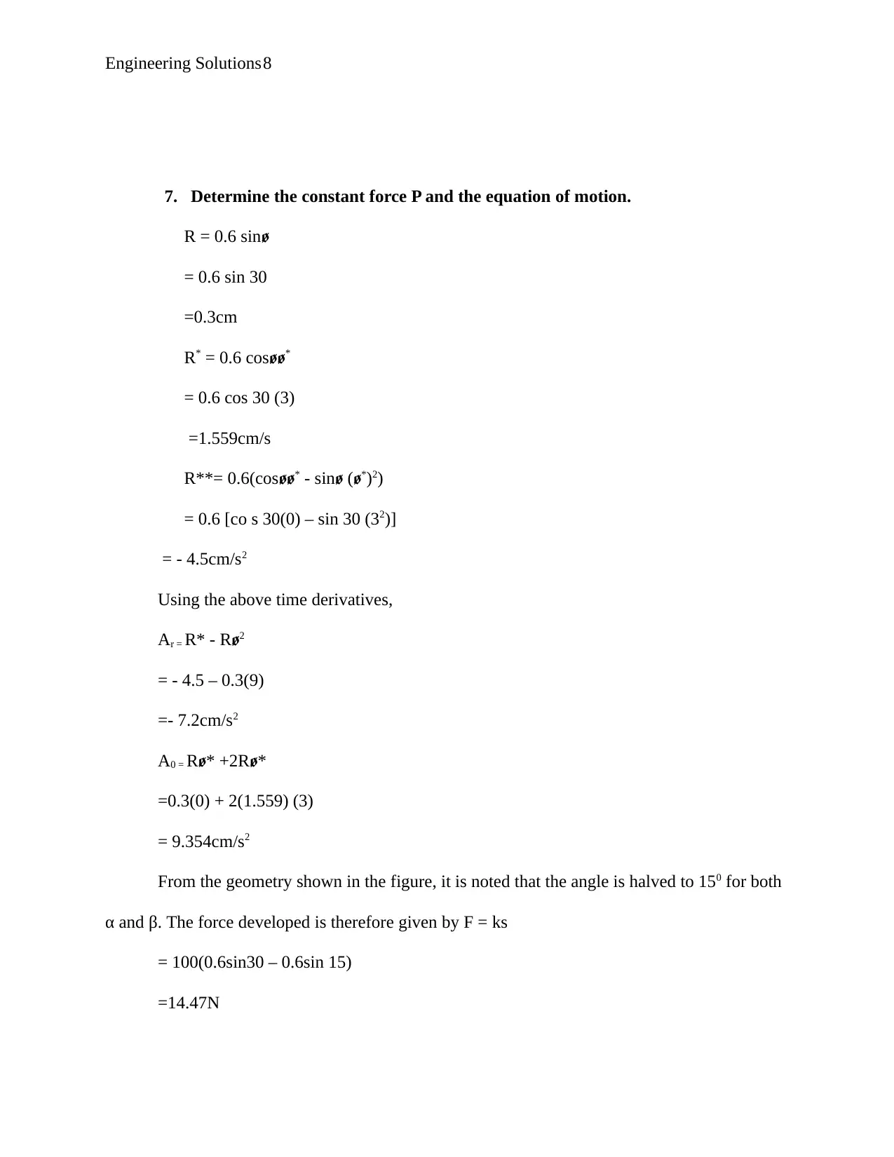
7. Determine the constant force P and the equation of motion.
R = 0.6 sinꬾ
= 0.6 sin 30
=0.3cm
R* = 0.6 cosꬾꬾ*
= 0.6 cos 30 (3)
=1.559cm/s
R**= 0.6(cosꬾꬾ* - sin (ꬾ ꬾ*)2)
= 0.6 [co s 30(0) – sin 30 (32)]
= - 4.5cm/s2
Using the above time derivatives,
Αr = R* - Rꬾ2
= - 4.5 – 0.3(9)
=- 7.2cm/s2
A0 = Rꬾ* +2Rꬾ*
=0.3(0) + 2(1.559) (3)
= 9.354cm/s2
From the geometry shown in the figure, it is noted that the angle is halved to 150 for both
α and β. The force developed is therefore given by F = ks
= 100(0.6sin30 – 0.6sin 15)
=14.47N
Engineering Solutions9
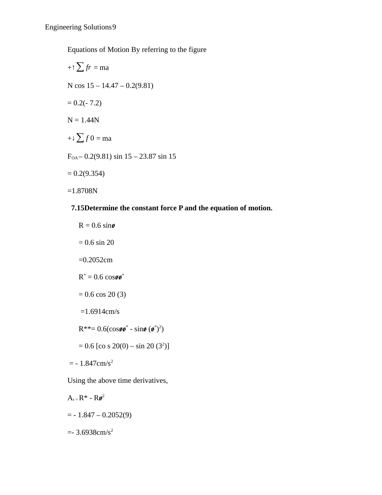
Equations of Motion By referring to the figure
+↑∑ fr = ma
N cos 15 – 14.47 – 0.2(9.81)
= 0.2(- 7.2)
N = 1.44N
+↓∑ f 0 = ma
FOA – 0.2(9.81) sin 15 – 23.87 sin 15
= 0.2(9.354)
=1.8708N
7.15Determine the constant force P and the equation of motion.
R = 0.6 sinꬾ
= 0.6 sin 20
=0.2052cm
R* = 0.6 cosꬾꬾ*
= 0.6 cos 20 (3)
=1.6914cm/s
R**= 0.6(cosꬾꬾ* - sin (ꬾ ꬾ*)2)
= 0.6 [co s 20(0) – sin 20 (32)]
= - 1.847cm/s2
Using the above time derivatives,
Αr = R* - Rꬾ2
= - 1.847 – 0.2052(9)
=- 3.6938cm/s2
⊘ This is a preview!⊘
Do you want full access?
Subscribe today to unlock all pages.

Trusted by 1+ million students worldwide
Engineering Solutions10
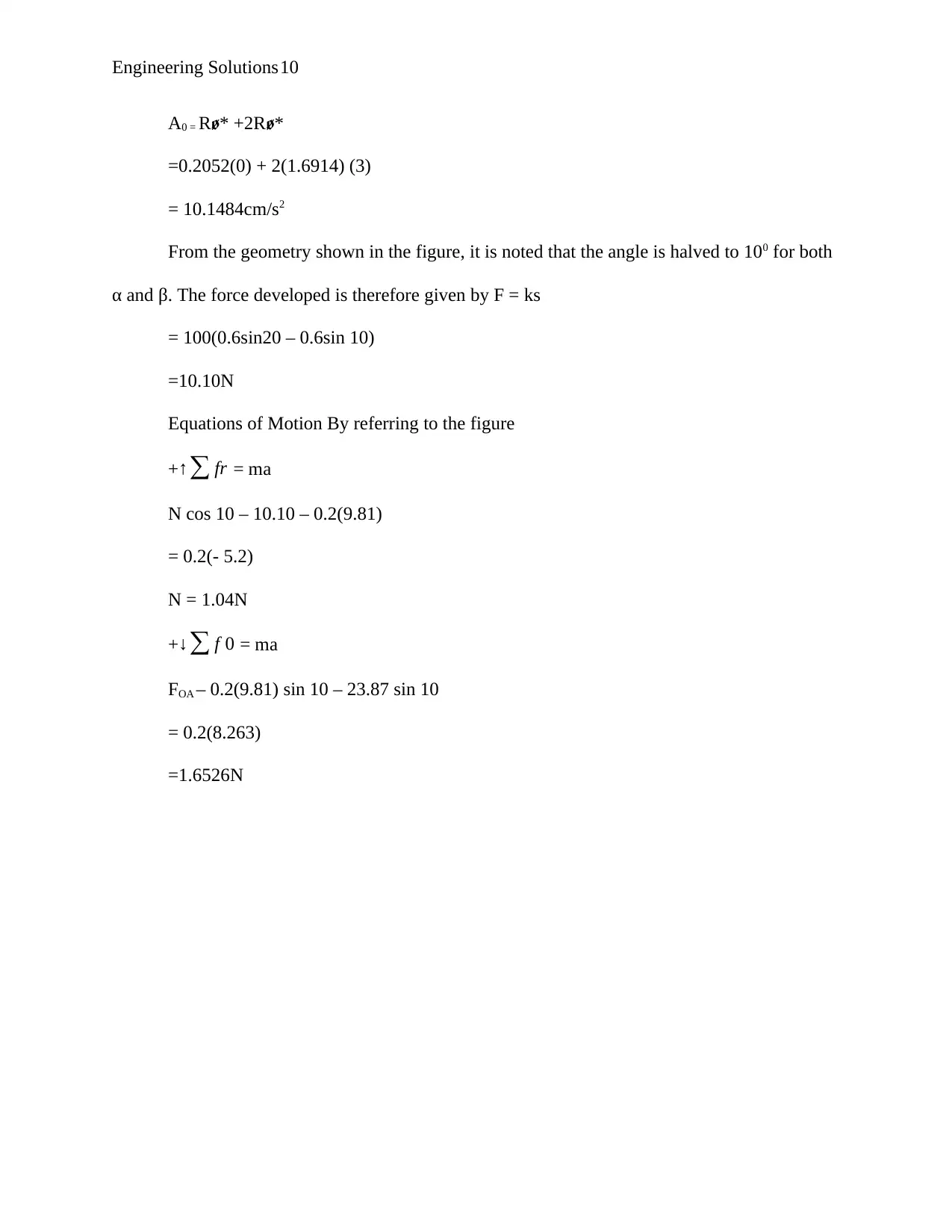
A0 = Rꬾ* +2Rꬾ*
=0.2052(0) + 2(1.6914) (3)
= 10.1484cm/s2
From the geometry shown in the figure, it is noted that the angle is halved to 100 for both
α and β. The force developed is therefore given by F = ks
= 100(0.6sin20 – 0.6sin 10)
=10.10N
Equations of Motion By referring to the figure
+↑∑ fr = ma
N cos 10 – 10.10 – 0.2(9.81)
= 0.2(- 5.2)
N = 1.04N
+↓∑ f 0 = ma
FOA – 0.2(9.81) sin 10 – 23.87 sin 10
= 0.2(8.263)
=1.6526N
Paraphrase This Document
Need a fresh take? Get an instant paraphrase of this document with our AI Paraphraser
Engineering Solutions11
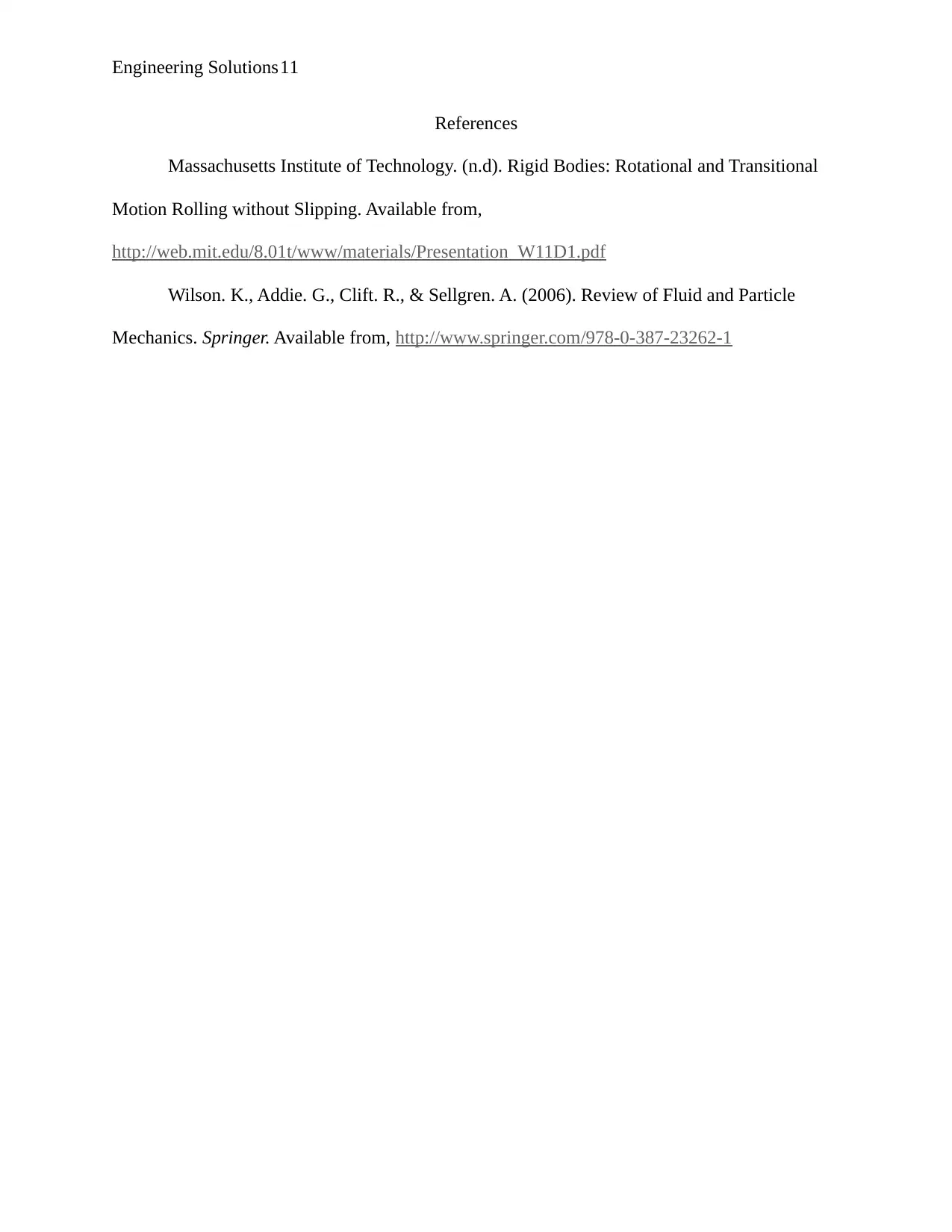
References
Massachusetts Institute of Technology. (n.d). Rigid Bodies: Rotational and Transitional
Motion Rolling without Slipping. Available from,
http://web.mit.edu/8.01t/www/materials/Presentation_W11D1.pdf
Wilson. K., Addie. G., Clift. R., & Sellgren. A. (2006). Review of Fluid and Particle
Mechanics. Springer. Available from, http://www.springer.com/978-0-387-23262-1

Engineering Solutions12
⊘ This is a preview!⊘
Do you want full access?
Subscribe today to unlock all pages.

Trusted by 1+ million students worldwide
1 out of 14
Your All-in-One AI-Powered Toolkit for Academic Success.
+13062052269
info@desklib.com
Available 24*7 on WhatsApp / Email
![[object Object]](/_next/static/media/star-bottom.7253800d.svg)
Unlock your academic potential
Copyright © 2020–2026 A2Z Services. All Rights Reserved. Developed and managed by ZUCOL.