Detailed Pump System Design and Analysis for Engineering Project

Verified

Added on  2023/03/23

|12
|1185
|21
Project
AI Summary
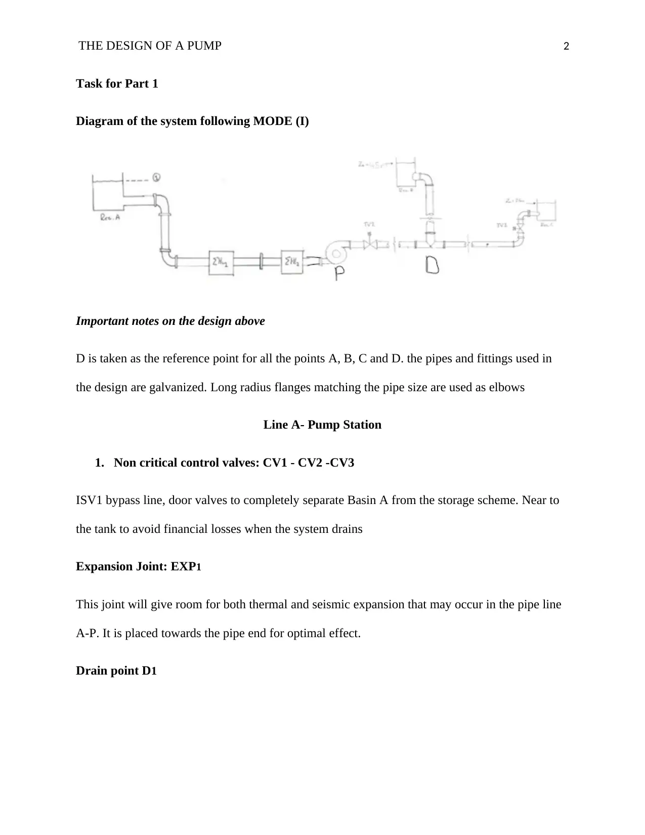
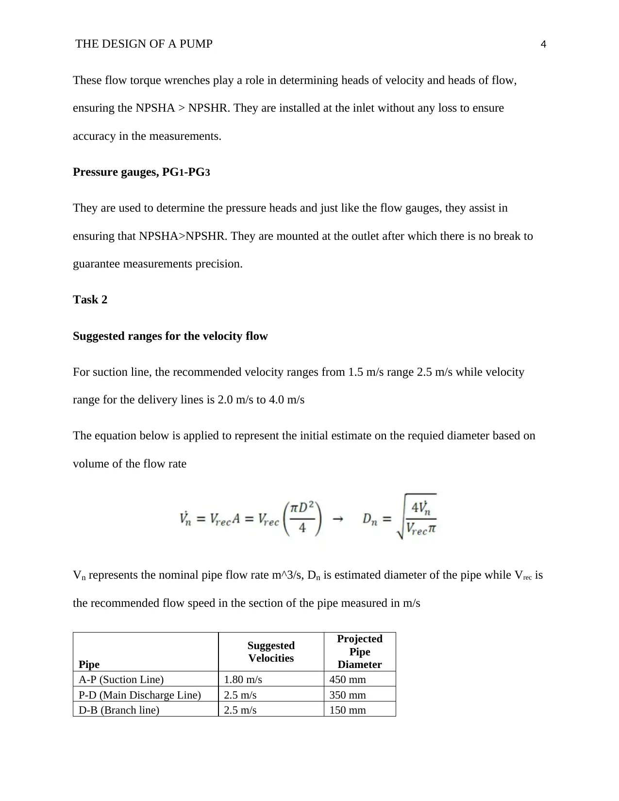
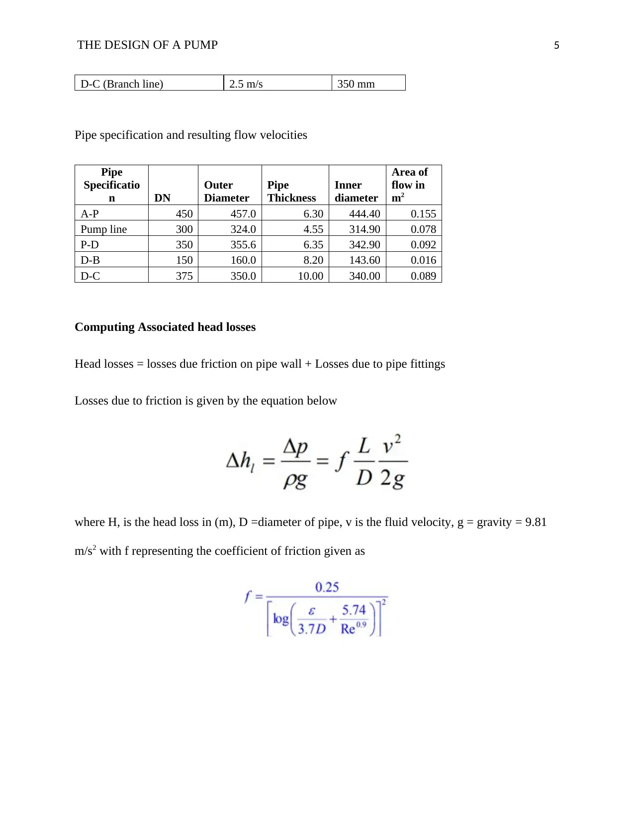
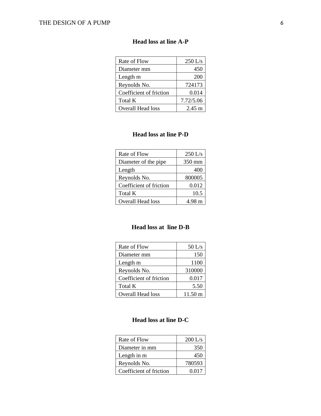
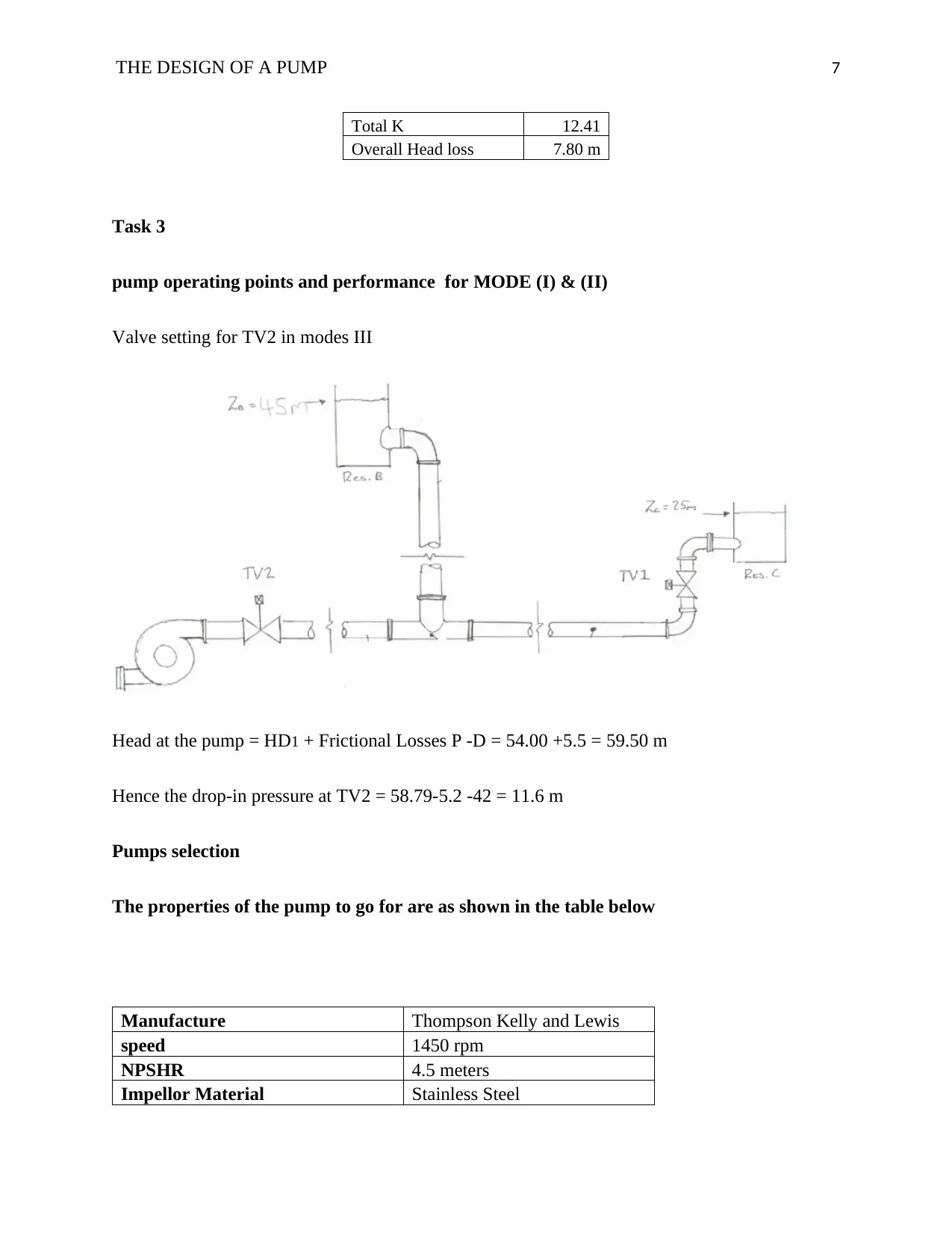
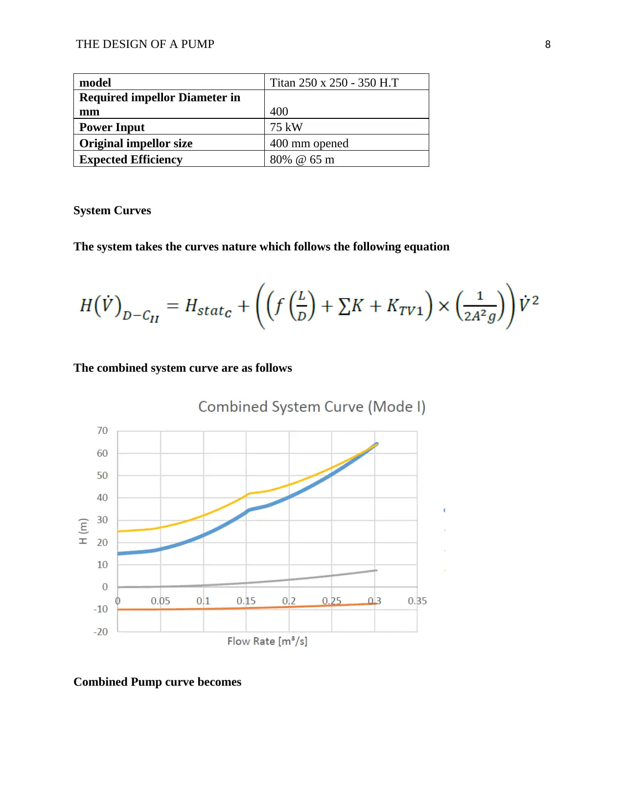
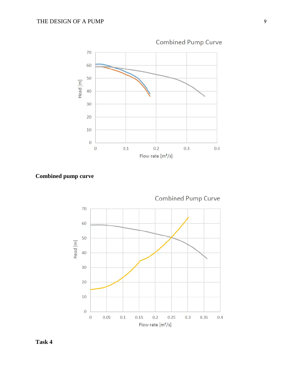
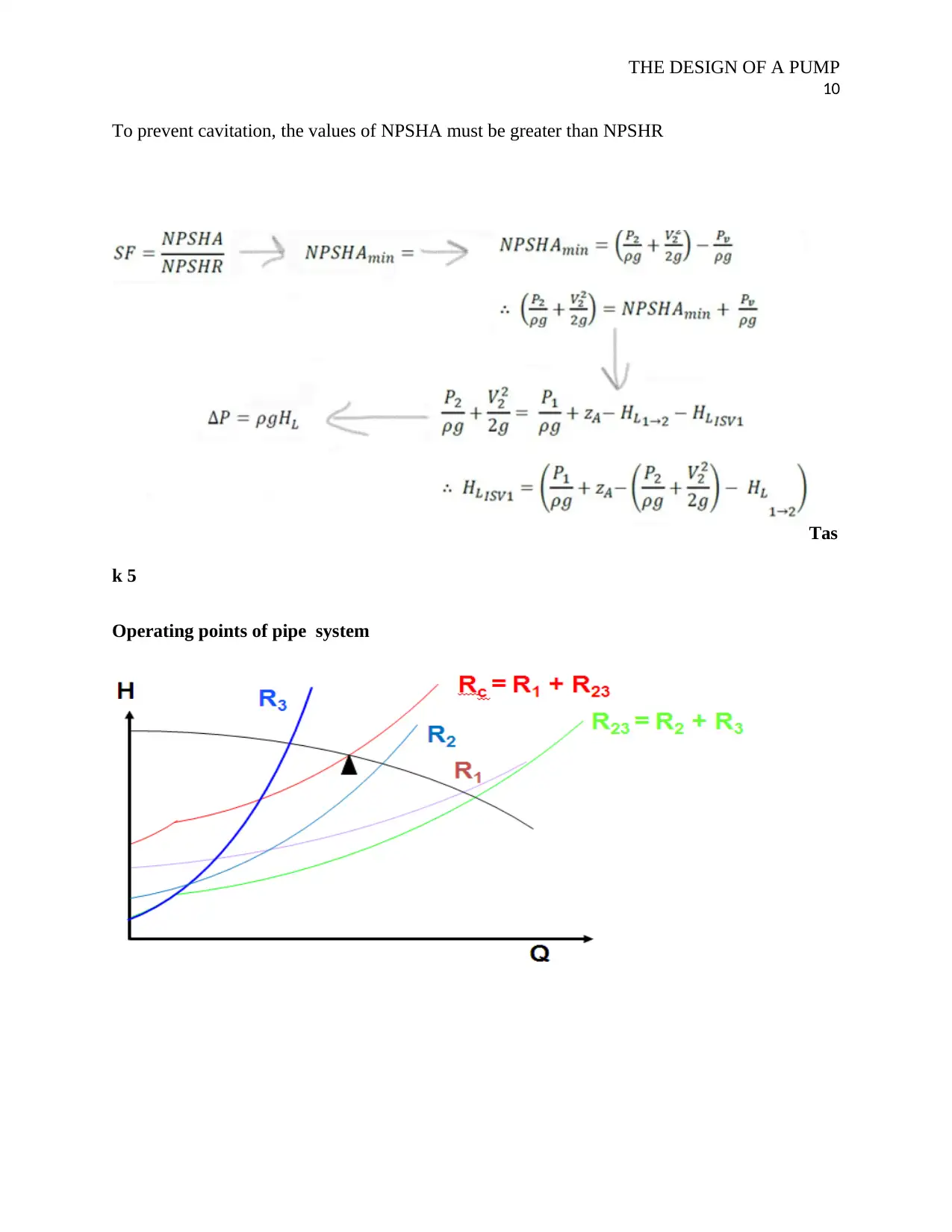
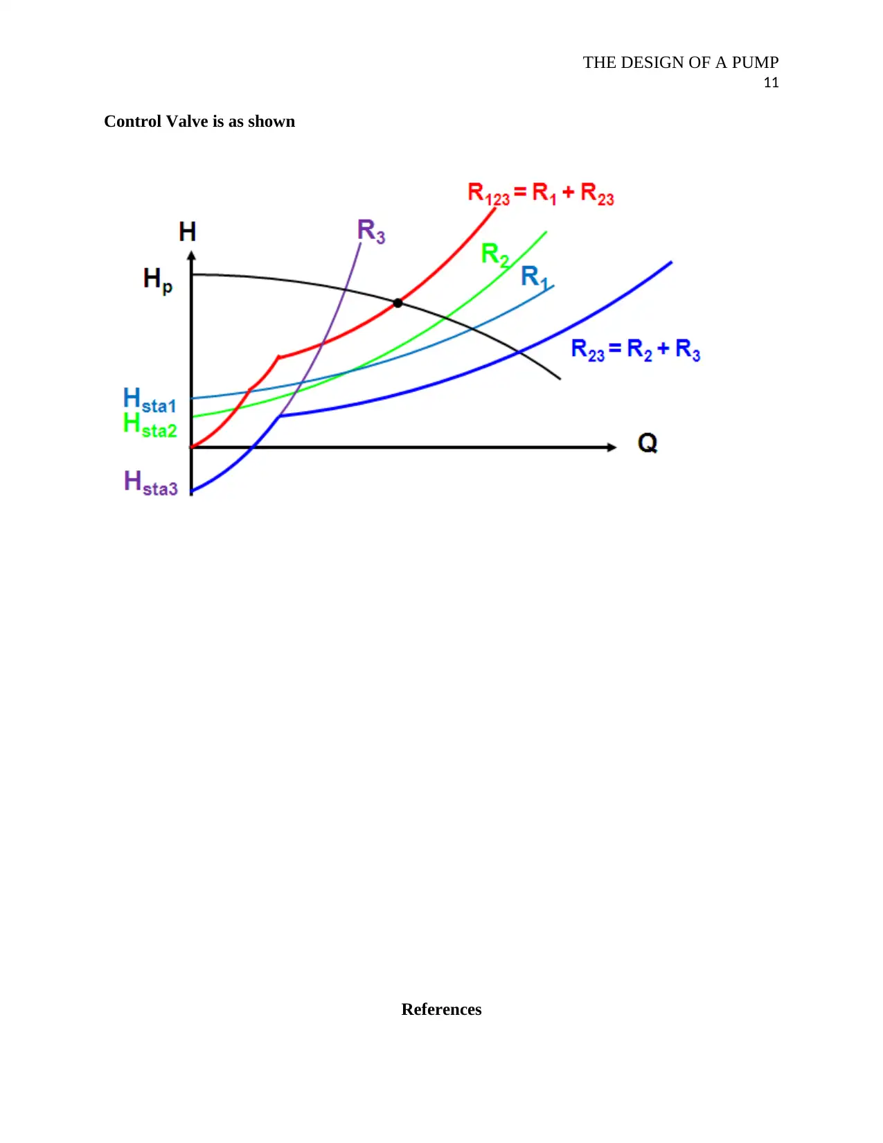
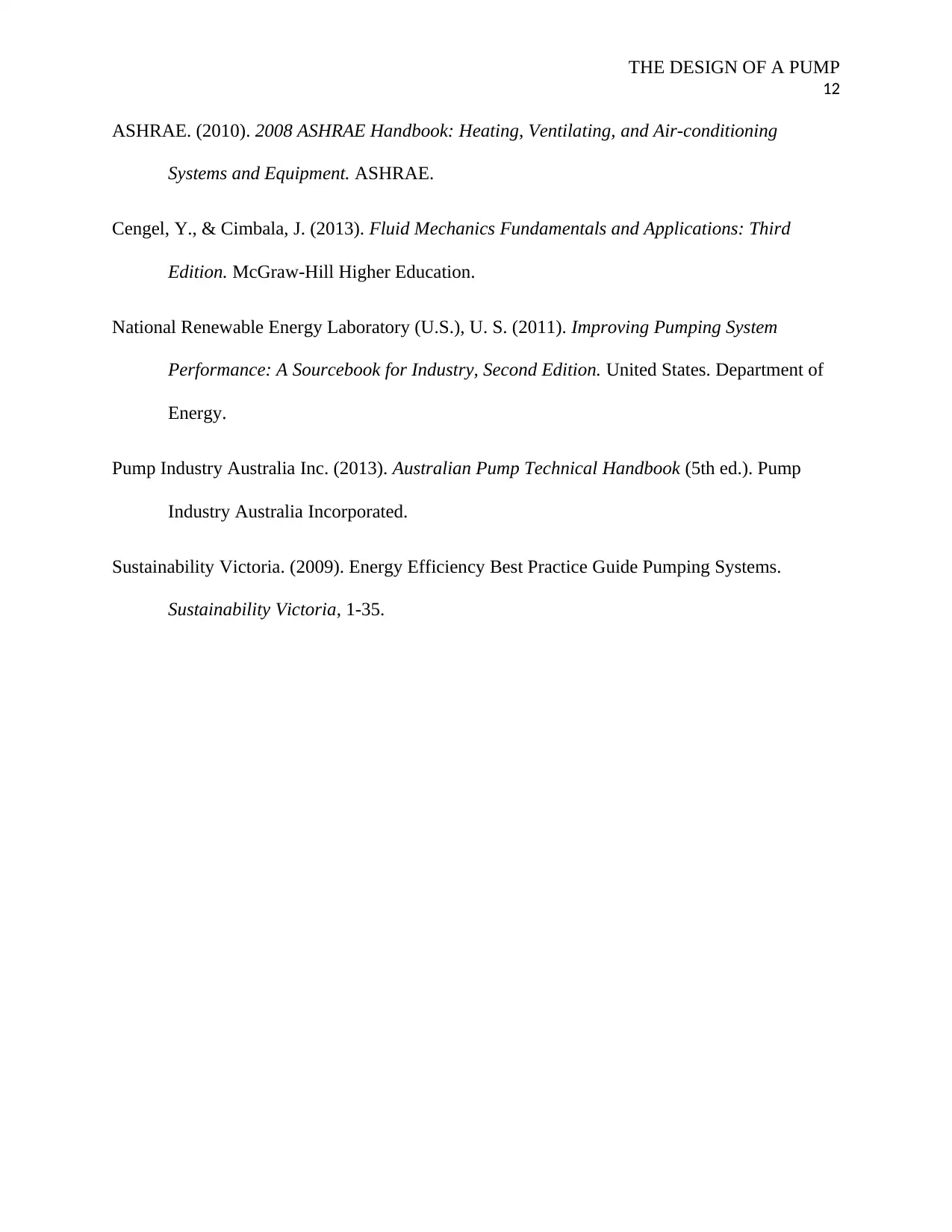
This project report details the design and analysis of a pump system, addressing various aspects from initial design to performance evaluation. The project includes a system diagram with component specifications, such as pipe sizes, valve placements, and expansion joints, using galvanized pipes. It covers velocity flow ranges for suction and delivery lines, calculating pipe diameters based on flow rates, and determining head losses due to friction and fittings. The report also analyzes pump operating points for different modes, including valve settings and pump selection based on manufacturer specifications, speed, and impeller material. Furthermore, it presents system curves, the combined pump curve, and considerations for preventing cavitation. The project concludes with references to relevant industry standards and publications.
Document Page
Running head: THE DESIGN OF A PUMP SYSTEM 1
Pumping system design
Firstname Lastname
Name of Institution
tabler-icon-diamond-filled.svg

Secure Best Marks with AI Grader

Need help grading? Try our AI Grader for instant feedback on your assignments.
Document Page
THE DESIGN OF A PUMP 2
Task for Part 1
Diagram of the system following MODE (I)
Important notes on the design above
D is taken as the reference point for all the points A, B, C and D. the pipes and fittings used in
the design are galvanized. Long radius flanges matching the pipe size are used as elbows
Line A- Pump Station
1. Non critical control valves: CV1 - CV2 -CV3
ISV1 bypass line, door valves to completely separate Basin A from the storage scheme. Near to
the tank to avoid financial losses when the system drains
Expansion Joint: EXP1
This joint will give room for both thermal and seismic expansion that may occur in the pipe line
A-P. It is placed towards the pipe end for optimal effect.
Drain point D1
Document Page
THE DESIGN OF A PUMP 3
This will form the drain at lower points for the pipe line A-P in certain scenario, draining may
be done for maintenance. This drain point is located at the lowest point to allow complete
drainage for line A-P.
To control NPSHA, Suction Isolation Valve, ISV1 Butterfly Suction Isolation Valve (as required
by architecture). Located near the tank to facilitate maintenance
Non critical control valves, CV4
Valve CV4 is an optional valve in this case. It served in maintenance of drainage line since it is
the international segregation of line A-Pump station. Pump isolation valve can serve similar
purpose as this valve.
Series arrangement for the Pump Station in obtaining volume flow rate
Critical valves CV5-CV6-CV7
The main role of these valves is to reduce waste volume circulation and steadfast in circulation.
They are standby and placed at the inlet of each line.
Expansion joints 2 and 4
Joint extension to enable pumping lines to expand. Also provide damping of vibrations
Strainers 1 and 3
These strainers positioned just before the pump outlet are used to remove contaminants before
they enter the tank..
Flow gauges, FG1-FG3
Document Page
THE DESIGN OF A PUMP 4
These flow torque wrenches play a role in determining heads of velocity and heads of flow,
ensuring the NPSHA > NPSHR. They are installed at the inlet without any loss to ensure
accuracy in the measurements.
Pressure gauges, PG1-PG3
They are used to determine the pressure heads and just like the flow gauges, they assist in
ensuring that NPSHA>NPSHR. They are mounted at the outlet after which there is no break to
guarantee measurements precision.
Task 2
Suggested ranges for the velocity flow
For suction line, the recommended velocity ranges from 1.5 m/s range 2.5 m/s while velocity
range for the delivery lines is 2.0 m/s to 4.0 m/s
The equation below is applied to represent the initial estimate on the requied diameter based on
volume of the flow rate
Vn represents the nominal pipe flow rate m^3/s, Dn is estimated diameter of the pipe while Vrec is
the recommended flow speed in the section of the pipe measured in m/s
Pipe
Suggested
Velocities
Projected
Pipe
Diameter
A-P (Suction Line) 1.80 m/s 450 mm
P-D (Main Discharge Line) 2.5 m/s 350 mm
D-B (Branch line) 2.5 m/s 150 mm
tabler-icon-diamond-filled.svg

Secure Best Marks with AI Grader

Need help grading? Try our AI Grader for instant feedback on your assignments.
Document Page
THE DESIGN OF A PUMP 5
D-C (Branch line) 2.5 m/s 350 mm
Pipe specification and resulting flow velocities
Pipe
Specificatio
n DN
Outer
Diameter
Pipe
Thickness
Inner
diameter
Area of
flow in
m2
A-P 450 457.0 6.30 444.40 0.155
Pump line 300 324.0 4.55 314.90 0.078
P-D 350 355.6 6.35 342.90 0.092
D-B 150 160.0 8.20 143.60 0.016
D-C 375 350.0 10.00 340.00 0.089
Computing Associated head losses
Head losses = losses due friction on pipe wall + Losses due to pipe fittings
Losses due to friction is given by the equation below
where H, is the head loss in (m), D =diameter of pipe, v is the fluid velocity, g = gravity = 9.81
m/s2 with f representing the coefficient of friction given as
Document Page
THE DESIGN OF A PUMP 6
Head loss at line A-P
Rate of Flow 250 L/s
Diameter mm 450
Length m 200
Reynolds No. 724173
Coefficient of friction 0.014
Total K 7.72/5.06
Overall Head loss 2.45 m
Head loss at line P-D
Rate of Flow 250 L/s
Diameter of the pipe 350 mm
Length 400
Reynolds No. 800005
Coefficient of friction 0.012
Total K 10.5
Overall Head loss 4.98 m
Head loss at line D-B
Rate of Flow 50 L/s
Diameter mm 150
Length m 1100
Reynolds No. 310000
Coefficient of friction 0.017
Total K 5.50
Overall Head loss 11.50 m
Head loss at line D-C
Rate of Flow 200 L/s
Diameter in mm 350
Length in m 450
Reynolds No. 780593
Coefficient of friction 0.017
Document Page
THE DESIGN OF A PUMP 7
Total K 12.41
Overall Head loss 7.80 m
Task 3
pump operating points and performance for MODE (I) & (II)
Valve setting for TV2 in modes III
Head at the pump = HD1 + Frictional Losses P -D = 54.00 +5.5 = 59.50 m
Hence the drop-in pressure at TV2 = 58.79-5.2 -42 = 11.6 m
Pumps selection
The properties of the pump to go for are as shown in the table below
Manufacture Thompson Kelly and Lewis
speed 1450 rpm
NPSHR 4.5 meters
Impellor Material Stainless Steel
tabler-icon-diamond-filled.svg

Paraphrase This Document

Need a fresh take? Get an instant paraphrase of this document with our AI Paraphraser
Document Page
THE DESIGN OF A PUMP 8
model Titan 250 x 250 - 350 H.T
Required impellor Diameter in
mm 400
Power Input 75 kW
Original impellor size 400 mm opened
Expected Efficiency 80% @ 65 m
System Curves
The system takes the curves nature which follows the following equation
The combined system curve are as follows
Combined Pump curve becomes
Document Page
THE DESIGN OF A PUMP 9
Combined pump curve
Task 4
Document Page
THE DESIGN OF A PUMP
10
To prevent cavitation, the values of NPSHA must be greater than NPSHR
Tas
k 5
Operating points of pipe system
tabler-icon-diamond-filled.svg

Secure Best Marks with AI Grader

Need help grading? Try our AI Grader for instant feedback on your assignments.
Document Page
THE DESIGN OF A PUMP
11
Control Valve is as shown
References
Document Page
THE DESIGN OF A PUMP
12
ASHRAE. (2010). 2008 ASHRAE Handbook: Heating, Ventilating, and Air-conditioning
Systems and Equipment. ASHRAE.
Cengel, Y., & Cimbala, J. (2013). Fluid Mechanics Fundamentals and Applications: Third
Edition. McGraw-Hill Higher Education.
National Renewable Energy Laboratory (U.S.), U. S. (2011). Improving Pumping System
Performance: A Sourcebook for Industry, Second Edition. United States. Department of
Energy.
Pump Industry Australia Inc. (2013). Australian Pump Technical Handbook (5th ed.). Pump
Industry Australia Incorporated.
Sustainability Victoria. (2009). Energy Efficiency Best Practice Guide Pumping Systems.
Sustainability Victoria, 1-35.
chevron_up_icon
1 out of 12
circle_padding
hide_on_mobile
zoom_out_icon
logo.png

Your All-in-One AI-Powered Toolkit for Academic Success.

Available 24*7 on WhatsApp / Email

[object Object]