Report on Enrolment and Timetabling System UML Diagram - MIS501

Verified

Added on  2022/09/28

|8
|1354
|24
Report
AI Summary
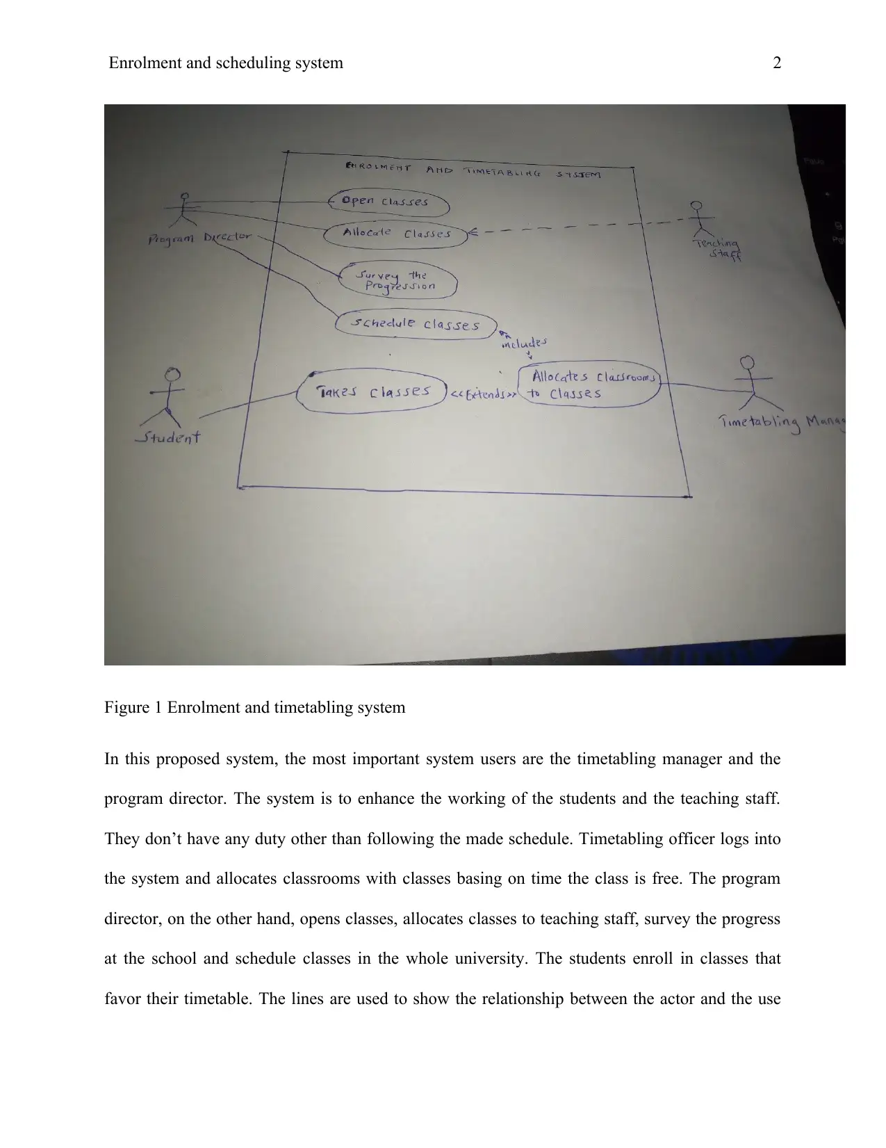
This report provides an in-depth analysis of a web-based enrolment and timetabling system, focusing on the application of UML diagrams in its design. The report begins with an introduction that highlights the common challenges of resource allocation in educational institutions and the need for an automated system. It then delves into the specifics of the system's UML diagrams, particularly a use case diagram, illustrating actors such as the Program Director, Timetabling Officer, and Students, and their respective use cases like opening classes, scheduling, and enrollment. The report emphasizes the importance of use case diagrams in identifying system users and requirements, facilitating proper planning and modular development. It also acknowledges the limitations of use case diagrams, such as their inability to depict dynamic system processes. The conclusion reiterates the significance of UML diagrams in documenting system requirements and guiding the development process. References to relevant research papers are also included to support the analysis.
Document Page
Running head: Enrolment and Timetabling system 1
Enrolment and Timetabling System.
Student Name
Institution
Professor’s Name
Date
tabler-icon-diamond-filled.svg

Secure Best Marks with AI Grader

Need help grading? Try our AI Grader for instant feedback on your assignments.
Document Page
Enrolment and scheduling system 2
Table of Contents
1 Introduction...................................................................................................................................3
2 UML Diagram..............................................................................................................................3
2.1 Use case diagram...................................................................................................................3
Importance of use case diagram modelling.................................................................................6
Limitations of use case diagram......................................................................................................6
3 Conclusion....................................................................................................................................7
References........................................................................................................................................8
Document Page
Enrolment and scheduling system 2
1 Introduction
A university, unlike other learning institutions, accommodates a lot of people. Many people are
enrolled in doing different programs but they should all be monitored. A learning institution is a
busy organization and involves many activities. All these activities have to be planned for their
success. Timetabling is a very common problem in all most all institutions. For example, you
may find a school providing a provisional timetable to be checked by users for error before the
final one is made. This is very tiresome and a lot of errors may be made since human eyes may
not be able to filter all the errors. The development of a web-based enrolment and timetabling
system will help solve this problem of poor resource allocation. The system will allow users to
use the system anywhere using either phones or computers. The system will not allow double
allocation of classes hence promoting accuracy. It will allow multiple users to use the system at
once. The system will also be very strict on time in that it will not allow a single classroom to be
assigned more than one class at the same time. This will at the end have helped solve the
scheduling problem.
2 UML Diagram
Unified Modelling Language diagrams are diagrams used in system analysis and design when
designing the proposed system. A prototype of the system is come up with to show the system
users and developers an overview of the final project. System analysis is very important as it
helps the developers collect all the resources, they will need during system development before
the real job starts.
2.1 Use case diagram
Document Page
Enrolment and scheduling system 2
This is a UML diagram showing the system users (Actors) and their duties in the system (Use
cases) within the system to develop. While drawing, actors are using people-like images while
the use cases use ovals with wordings inside (Singh & Sharma, 2015).
The following are users expected in our enrolment and timetabling system;
i) Program director- opens classes, allocate classes to teaching staff
ii) Timetabling officer – schedule classes in rooms for the whole university
iii) Students- Enroll in classes.
iv) The system is expected to generate a timetable for users. This is a use case that will
be performed by all the system users because they will all need a timetable.
tabler-icon-diamond-filled.svg

Secure Best Marks with AI Grader

Need help grading? Try our AI Grader for instant feedback on your assignments.
Document Page
Enrolment and scheduling system 2
Figure 1 Enrolment and timetabling system
In this proposed system, the most important system users are the timetabling manager and the
program director. The system is to enhance the working of the students and the teaching staff.
They don’t have any duty other than following the made schedule. Timetabling officer logs into
the system and allocates classrooms with classes basing on time the class is free. The program
director, on the other hand, opens classes, allocates classes to teaching staff, survey the progress
at the school and schedule classes in the whole university. The students enroll in classes that
favor their timetable. The lines are used to show the relationship between the actor and the use
Document Page
Enrolment and scheduling system 2
case, related use cases, and related actors. The lines may be continuing or dotted. A dotted line
shows that one object depends on the other. Types of relationships generalization, association
and including. All the system users are expected to print the time table at the end because the
system will be enabled to. Some use cases fully depend on others. For example, for the students
to take classes, the scheduling officer must have scheduled classes, the teacher must have been
allocated classes, the student should have already made a personal timetable.
Importance of use case diagram modelling.
It helps system analyst to know the expected system users. For a use case diagram to be
complete, all the users must be indicated in the diagram. Knowing the users is necessary as it
helps the development team to now the targeted group (Chebotko, Kashlev & Lu, 2015).
The developers can identify user requirements. User requirements are so important since before
the system is deployed to the market, acceptance testing must be done. Once the user
requirements are known solving them becomes very simple.
Enables proper planning as the system development team will easily know the modules that
make up the system. These modules can be divided into developers for them to apply modularity
in their development process making the whole process easy.
Limitations of use case diagram
The use case diagrams do not show the dynamic parts of the system. It only shows those parts
that do not include interactivity (Nassif, Capretz & Ho, 2016).
Document Page
Enrolment and scheduling system 2
The procedure in which the activities will occur is not demonstrated in the system. Unlike the
activity diagram, sequence diagram, and state machine diagrams that show the flow of activities,
a sequence diagram randomly shows the activities expected to take place in the system.
3 Conclusion
A use case diagram can be used by the developers to document the system requirements
expected by the final users and those desired by the users themselves. The actors are used to
show what the system is supposed to do in the long run. The better you develop the use case
diagram, the more important it becomes to the system development team. Use case diagram is a
better source of both user and system requirements because the use cases of the system are what
the system is supposed to do. To be able to draw a good use case diagram, you have to
understand the system well first, know UML terms used and know the kind of symbols employed
when drawing different diagrams (Elsawah, Guillaume, Filatova, Rook & Jakeman, 2015) The
symbols used to depict the kind of diagram drawn (Dori, 2016). To better your drawing skills,
you have to find more information on UML diagrams. This will provide you with background
information.
tabler-icon-diamond-filled.svg

Paraphrase This Document

Need a fresh take? Get an instant paraphrase of this document with our AI Paraphraser
Document Page
Enrolment and scheduling system 2
References
Chebotko, A., Kashlev, A., & Lu, S. (2015, June). A big data modeling methodology for Apache
Cassandra. In 2015 IEEE International Congress on Big Data (pp. 238-245). IEEE.
Dori, D. (2016). SysML: Use Case, Block, and State Machine Diagrams. In Model-Based
Systems Engineering with OPM and SysML (pp. 29-35). Springer, New York, NY.
Elsawah, S., Guillaume, J. H., Filatova, T., Rook, J., & Jakeman, A. J. (2015). A methodology
for eliciting, representing, and analysing stakeholder knowledge for decision making on
complex socio-ecological systems: From cognitive maps to agent-based models. Journal
of environmental management, 151, 500-516.
Nassif, A. B., Capretz, L. F., & Ho, D. (2016). Enhancing use case points estimation method
using soft computing techniques. arXiv preprint arXiv:1612.01078.
Singh, A., & Sharma, E. S. (2015). Functional Test Cases Generation Based on Automated
Generated Use Case Diagram. Chandigarh University, International Journal of
Innovative Research in Advanced Engineering (IJIRAE), 2(8).
chevron_up_icon
1 out of 8
circle_padding
hide_on_mobile
zoom_out_icon
logo.png

Your All-in-One AI-Powered Toolkit for Academic Success.

Available 24*7 on WhatsApp / Email

[object Object]