ENRP20001: IC Engine Cooling System Optimization at CQUniversity
VerifiedAdded on 2024/06/28
|40
|7989
|68
Project
AI Summary
This project focuses on optimizing the cooling system in an internal combustion (IC) engine using MATLAB simulation. The study involves creating a stimulated model to analyze various performance parameters related to engine type, vehicle type, and number of cylinders. The report details the process of developing the MATLAB model and the parameters used for optimization. It includes a literature review of relevant research on IC engine performance, emissions, and cooling system optimization techniques. The methodology section describes the simulation process and model creation, comparing reference values with optimized values. The project also includes a Gantt chart for planning and concludes with a summary of the findings. Desklib provides access to this project and many other solved assignments for students.
STUDENT NAME: AMANDEEP SINGH
STUDENT ID: 12066802
Unit: ENRP20001 ENGINEERING RESEARCH PROJECT PLANNING
Unit coordinator: ABDUL MAZID
Supervisor – NIRMAL MANDAL
Week of Submission: 11
Date of Submission: 5th June 2019
Title – OPTIMIZATION OF COOLING SYSTEM IN IC ENGINE
Name of Submission – FINAL THESIS
School of Engineering and Technology
CQ University
1
Paraphrase This Document
Need a fresh take? Get an instant paraphrase of this document with our AI Paraphraser
Abstract
In this study, a stimulated model is created using MATLAB software to optimize an engine to
study about various aspects and scenarios about performance parameters of an engine which varies
from their vehicle type, engine type, number of cylinders. Later in this assignment there is detailed
process layout of developing stimulated model on MATLAB and how different parameters were
used to optimize the model.
The literature review describes the important research works about the Internal combustion
engine’s performance and emission and method implemented by researchers for proper
optimization of cooing system in Internal Combustion engine. The methodology describes the
stimulated model, how it is processed and how the model is created.
2
Acknowledgement
I would like to acknowledge the support of my unit coordinator – Mr. Abdul Mazid and my
supervisor – Mr. Nirmal Mandal for their guidance, motivation and feedbacks for the research
work. I would also like to acknowledge the support of Central Queensland University for providing
all the useful resources for completion of this research work.
3
⊘ This is a preview!⊘
Do you want full access?
Subscribe today to unlock all pages.
Trusted by 1+ million students worldwide
Table of Contents
Abstract............................................................................................................................................2
Acknowledgement........................................................................................................................... 3
List of Figures..................................................................................................................................6
List of Tables................................................................................................................................... 6
1. Introduction................................................................................................................................7
1.1. Background information................................................................................................7
1.2 Objective............................................................................................................................... 9
1.3 Scopes of the study........................................................................................................ 10
1.3.1 Parameters for Optimizing IC engine cooling systems......................................11
1.3.2 Milestone.................................................................................................................11
1.4 Deliverables........................................................................................................................12
1.4.1 Radiator construction.................................................................................................12
1.4.2 Coolant pump..............................................................................................................13
1.4.2 Heater...............................................................................................................................14
1.4.4 Temperature control.................................................................................................. 14
1.5 Significance and contribution of the study...................................................................... 16
2. Literature Review.................................................................................................................... 17
3. Methodology............................................................................................................................. 26
3.1 Introduction........................................................................................................................26
3.2 Stimulation Process........................................................................................................... 26
3.3 Simulated Model................................................................................................................ 31
3.4 Reference value Vs Optimized value................................................................................32
3.5 Results................................................................................................................................. 32
3.6 Planning Gantt Chart........................................................................................................36
4
Paraphrase This Document
Need a fresh take? Get an instant paraphrase of this document with our AI Paraphraser
4. Conclusion................................................................................................................................ 37
5. References.................................................................................................................................38
5
5. References.................................................................................................................................38
5
List of Figures
Figure 1: Working of the Cooling system in an engine...................................................................9
Figure 2: A Cooling system in a 4-cylinder engine....................................................................... 10
Figure 3: Car Radiator...................................................................................................................13
Figure 4: Coolant pump................................................................................................................. 14
Figure 5: Heater............................................................................................................................. 14
Figure 6: Water flow control in an engine.....................................................................................15
Figure 7: Airflow in an engine.......................................................................................................16
Figure 8: Cooling System.............................................................................................................. 18
Figure 9: Radiant Cooling Process................................................................................................19
Figure 10: Car Cooling System..................................................................................................... 20
Figure 11: Water Flow Control......................................................................................................21
Figure 12: Air Flow Control System.............................................................................................22
Figure 13: MATLAB main window.............................................................................................. 26
Figure 14: Simulink start page.......................................................................................................27
Figure 15: Model design window.................................................................................................. 27
Figure 16: Simulink library browser..............................................................................................28
Figure 17: Simulink model preperation......................................................................................... 29
Figure 18: RUN button location window...................................................................................... 29
Figure 19: Parameter window........................................................................................................30
Figure 20: Simulated model...........................................................................................................31
Figure 21: Resultant graph 1..........................................................................................................33
Figure 22: Resultant graph 2..........................................................................................................34
Figure 23: Resultant graph 3..........................................................................................................35
Figure 24: Gantt Chart................................................................................................................... 36
List of Tables
Table 1: Reference vs Optimized value.........................................................................................32
6
⊘ This is a preview!⊘
Do you want full access?
Subscribe today to unlock all pages.
Trusted by 1+ million students worldwide
1. Introduction
According to this report title, this document consists study and analysis of different cooling
systems. Cooling systems have a large variety of mechanism, they are distributed on many bases
like on the basis of their coolant type like if they are water cooled or air cooled, another variety is
based upon their piston size and number of cylinders. This report covers and concludes all the
different variation of cooling systems and factors that affect their optimization.
Every invention after the invention of the wheel has somewhat been an energy source. Any gadget
we use nowadays is using some kind of energy and releasing some other kind of energy. But to
keep that emitting energy from harming our system we must build a counter system so that it
cannot overheat the system and overheat it.
The basic principle behind cooling system comes from thermodynamics. When a system generates
heat while running that generally an exothermic reaction which means that energy is generated in
the form of heat.
In the automobile industry, the cooling system plays a very important role because they’re
responsible for cooling the engine when they overheat so that they can perform faster and last
longer. The reason behind car engine heating up is that movement in the car axle is caused by
pistons and their cylinders and the friction between cylinders and pistons produce heat energy. This
results in heating of the whole engine. If the engine gets too hot too quickly without any cooling
system then the heat can cause deformity in engine parts which can cause accidents on road. So, it
is really important to use the cooling system in an automobile combustion system.
1.1. Background information
The cooling system can be defined as the process that helps the system in removing thermal energy
that is being generated in the engine during its processing combustion? This process redirects and
exerts the flow of excess heat generated in an engine due to its operation process and maintains the
optimum internal temperature of the system for it's successful and smooth operating. The cooling
system basically requires a coolant medium for their process of cooling which is generally fluid
based including air, water, or oil-based liquid. Based on the coolant medium, there are two types of
cooling system-
7
Paraphrase This Document
Need a fresh take? Get an instant paraphrase of this document with our AI Paraphraser
Air cooling system- In this process of the cooling system, the coolant is an air-based fluid. This
process is also known as direct cooling. In this process of the cooling system, the cooling medium
i.e. air is directly circulated to the engine system for its process of cooling.
The operation process of the air-cooling system- In this type of cooling system, the coolant
medium (air) is directly passed through the components of the engine system so as to minimize
the heat generated in the engine. Since the cooling medium in this type of cooling system is
directly in contact with the components of the engine, hence is termed direct cooling system
(Zaidan, 2018). Give a few examples of this type of cooling like motorcycles etc.
Liquid cooling system- In this process of the cooling system, the coolant medium is a liquid-based
fluid which can include water, oil, or other viscous liquid media. The process of cooling in the
liquid cooling system uses an indirect type of cooling method in which the actual process of
cooling i.e. air is not circulated in the engine system for cooling rather is used in cooling of the
coolant medium.
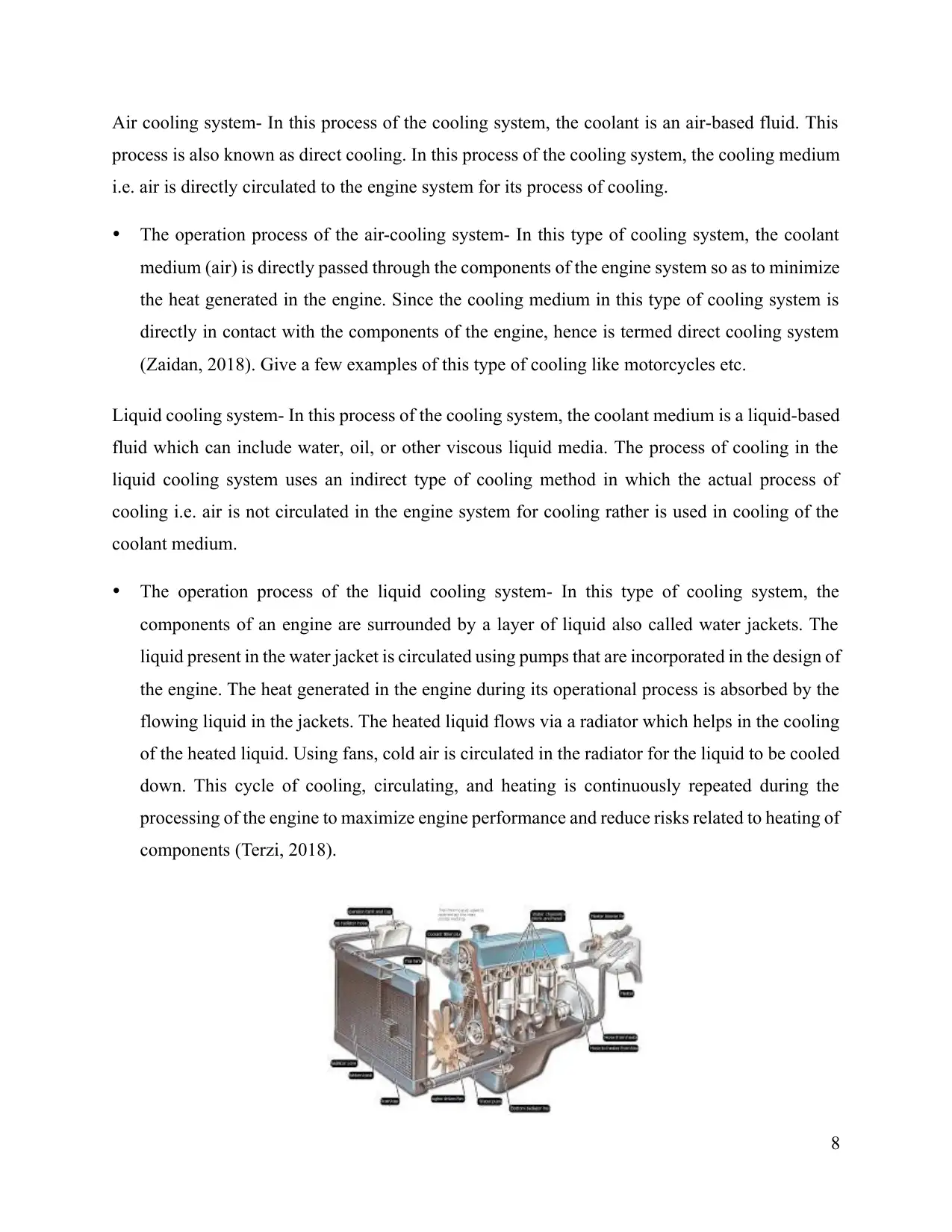
The operation process of the liquid cooling system- In this type of cooling system, the
components of an engine are surrounded by a layer of liquid also called water jackets. The
liquid present in the water jacket is circulated using pumps that are incorporated in the design of
the engine. The heat generated in the engine during its operational process is absorbed by the
flowing liquid in the jackets. The heated liquid flows via a radiator which helps in the cooling
of the heated liquid. Using fans, cold air is circulated in the radiator for the liquid to be cooled
down. This cycle of cooling, circulating, and heating is continuously repeated during the
processing of the engine to maximize engine performance and reduce risks related to heating of
components (Terzi, 2018).
8
process is also known as direct cooling. In this process of the cooling system, the cooling medium
i.e. air is directly circulated to the engine system for its process of cooling.
The operation process of the air-cooling system- In this type of cooling system, the coolant
medium (air) is directly passed through the components of the engine system so as to minimize
the heat generated in the engine. Since the cooling medium in this type of cooling system is
directly in contact with the components of the engine, hence is termed direct cooling system
(Zaidan, 2018). Give a few examples of this type of cooling like motorcycles etc.
Liquid cooling system- In this process of the cooling system, the coolant medium is a liquid-based
fluid which can include water, oil, or other viscous liquid media. The process of cooling in the
liquid cooling system uses an indirect type of cooling method in which the actual process of
cooling i.e. air is not circulated in the engine system for cooling rather is used in cooling of the
coolant medium.
The operation process of the liquid cooling system- In this type of cooling system, the
components of an engine are surrounded by a layer of liquid also called water jackets. The
liquid present in the water jacket is circulated using pumps that are incorporated in the design of
the engine. The heat generated in the engine during its operational process is absorbed by the
flowing liquid in the jackets. The heated liquid flows via a radiator which helps in the cooling
of the heated liquid. Using fans, cold air is circulated in the radiator for the liquid to be cooled
down. This cycle of cooling, circulating, and heating is continuously repeated during the
processing of the engine to maximize engine performance and reduce risks related to heating of
components (Terzi, 2018).
8
Figure 1: Working of the Cooling system in an engine
1.2 Objective
If we talk about the objective of the cooling system, it generally defines how the system or machine
that we are using is going to release its thermal heat. By the basic laws of thermodynamics. It is said
that any process no matter how big or small, it releases some energy in form of heat. But sometime
this released energy can also be harmful to the system if the system gets overheated then parts can
be damaged or worse the system can also shut down on its own. The cooling system is a vital
addition to the engines as by using this process, the engine can perform various tasks smoothly and
for elongated hours. Liquid cooling is the later designed cooling system that is designed to enhance
the performance of cooling in the engines. This type of cooling system benefits the engine in
various aspects such as the design of the liquid cooling system is compact, thus incorporates
portability factor in their design. Using a liquid cooling system, the components of the engine
system is evenly cooled which manage the operation ability of all the components in the engine
system. The process of direct cooling system also benefits the engine system as the design is simple
and the process of maintenance and repairing becomes easier. In this cooling system, there is no
liquid medium, thus the risk of leakage of coolants in the engine is totally eliminated. The cooling
system enhances engine performance by keeping the system cooled down to enhance the
processing of more tasks. The cooling system also increases the efficiency of an engine by keeping
its component cool and also improves production ability. The cooling system manages the heat of
the engine and enhances its long-term sustainability (Lekbir, 2018).
1.3 Scopes of the study
The scope of this study is learning about cooling systems and their application in IC engines.
Various automobile industries are dependent upon the latest cooling system so that their car’s
efficiency can be improved. The cooling system also has to be very fast because in many situations
system heat up instantly so it is very important to cool them immediately. This study focuses on the
cooling system of what type of engine? Engine. The cooling system is used in various engines that
exhibit heat generation. Current incorporating the cooling system in such engines helps the engine
to perform multiple tasks easily without the risks of damaging any vital or non-vital components of
an engine. Incorporating the cooling system has developed a new margin of threshold in the
9
⊘ This is a preview!⊘
Do you want full access?
Subscribe today to unlock all pages.
Trusted by 1+ million students worldwide
performance of the engine and also in its sustainability aspect. The advancements in the cooling
system include automation which manages the flow of heat in the processing of the engine by
automatically circulating coolants when the engine displays certain set threshold of heat generation
to cool the system back to optimum running temperature. It also deactivates the process when low
heat is being generated by the engine (Ma, et al., 2010)
.
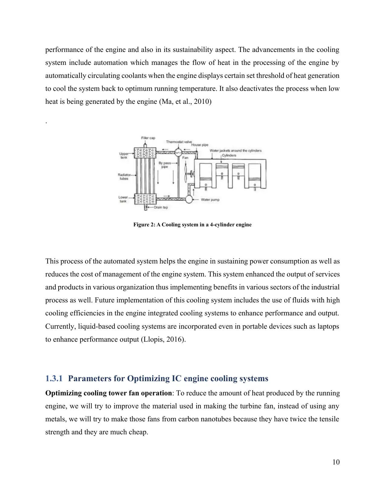
Figure 2: A Cooling system in a 4-cylinder engine
This process of the automated system helps the engine in sustaining power consumption as well as
reduces the cost of management of the engine system. This system enhanced the output of services
and products in various organization thus implementing benefits in various sectors of the industrial
process as well. Future implementation of this cooling system includes the use of fluids with high
cooling efficiencies in the engine integrated cooling systems to enhance performance and output.
Currently, liquid-based cooling systems are incorporated even in portable devices such as laptops
to enhance performance output (Llopis, 2016).
1.3.1 Parameters for Optimizing IC engine cooling systems
Optimizing cooling tower fan operation: To reduce the amount of heat produced by the running
engine, we will try to improve the material used in making the turbine fan, instead of using any
metals, we will try to make those fans from carbon nanotubes because they have twice the tensile
strength and they are much cheap.
10
system include automation which manages the flow of heat in the processing of the engine by
automatically circulating coolants when the engine displays certain set threshold of heat generation
to cool the system back to optimum running temperature. It also deactivates the process when low
heat is being generated by the engine (Ma, et al., 2010)
.
Figure 2: A Cooling system in a 4-cylinder engine
This process of the automated system helps the engine in sustaining power consumption as well as
reduces the cost of management of the engine system. This system enhanced the output of services
and products in various organization thus implementing benefits in various sectors of the industrial
process as well. Future implementation of this cooling system includes the use of fluids with high
cooling efficiencies in the engine integrated cooling systems to enhance performance and output.
Currently, liquid-based cooling systems are incorporated even in portable devices such as laptops
to enhance performance output (Llopis, 2016).
1.3.1 Parameters for Optimizing IC engine cooling systems
Optimizing cooling tower fan operation: To reduce the amount of heat produced by the running
engine, we will try to improve the material used in making the turbine fan, instead of using any
metals, we will try to make those fans from carbon nanotubes because they have twice the tensile
strength and they are much cheap.
10
Paraphrase This Document
Need a fresh take? Get an instant paraphrase of this document with our AI Paraphraser
Optimizing the cooling tower pump operation: Coolant in the engine has to be of high boiling
point. Which means it will take a long time to get to a heating point so it will keep the engine cool
for a long time. We will try some chemicals with a high boiling point can really make a huge
difference.
Optimizing the chiller compressor operation: We will try to minimize the temperature
difference across the heat pump. The method for doing this is by a continuous supply of coolants
like water or any other dense chemical so that it can maintain the temperature difference.
1.3.2 Milestone
Week 1: In week 1, we researched about cooling systems and various aspects of it. Learning from
various researched papers and generals was in the first week.
Week 4: In week 4, the project proposal was submitted. Project proposal means the topic on which
this project is based upon. The project proposal is a very crucial milestone because this stage will
decide the path, we have to take in order to move forward.
Week 7: In week 7, Literature review was made. A literature review is a document which is like
review paper of various published documents.
Week 9: In week 9, the presentation will be given so that every aspect can be discussed and
research can be presented.
Week 12: Week 12 is for finalizing the proposal and submitting the thesis with proper
documentation.
A special category of prototype internal combustion engines is being developed over a few years
because in order to improve efficiency there must be a way to reduce the amount of heat produced
in the engine. There are various experiments are going on to develop a prototype on this parameter.
Various leading industries are investing their time and money to come with new ways to cool the
engine in a faster and efficient way. This kind of engine is called adiabatic engine. Normally they
are diesel fuel engine with chambers for combustion alongside with a ceramic thermal coating on
the barrier. They also have less heat rejection or high-temperature core (Hamdy, et al., 2015).
11
There have been many specific requirements on a system of cooling the engines. Specific key has
responsibility for the whole functionality of the whole engine. If only one part overheats than the
whole system can get compromised which means the engine can degrade the quality of the vehicle.
The main factor of the varying cooling system from engine to the engine is the passage of coolant
flow which is different in various engines because in some cases engine requires one type of
cooling and in other it requires another type of cooling. Air cooling system also varies from type to
type which means they can get expensive in some cases for the sake of the engine’s quality.
1.4 Deliverables
Engines are cooled by the process of heat exchange which ultimately cools the engine which is the
major concept of cooling in automobiles but this process is not limited to just automobiles, many
aircraft which piston engine type or locomotives, motorcycles use this process to maintain their
engines efficiency
Circulating coolant by the process of liquid cooling is used in cooling of internal combustion
engine. The coolant flows through the engine block and reduces the heat output so that the engine
can maintain a decent temperature. The base of engine coolant is generally water with some cool
chemicals. In some cases, instead of water, the base can be synthetic engine oil.
1.4.1 Radiator construction
The part which is used for exchanging heat in a car engine is called a radiator. A pair of header
tanks are needed for radiator construction in an automobile. A radiator has many narrow passages
with a high surface area as compared to volume. This layer consists of various layers of metal
sheets which are pressed in such a way that they form a cooling channel. This part is prone towards
failing but it is less easy to repair than other parts (Daghigh & Shafieian, 2015).
In the earlier days, the concept behind a radiator was a structure like a honeycomb. Circular pipes
are combined together in the form of a hexagon from their ends using soldering and stacking. The
important part was that they are only joined from their end, which resulted in a solid water tank
with many tubes for air passage.
12
⊘ This is a preview!⊘
Do you want full access?
Subscribe today to unlock all pages.
Trusted by 1+ million students worldwide
1 out of 40
Your All-in-One AI-Powered Toolkit for Academic Success.
+13062052269
info@desklib.com
Available 24*7 on WhatsApp / Email
![[object Object]](/_next/static/media/star-bottom.7253800d.svg)
Unlock your academic potential
Copyright © 2020–2026 A2Z Services. All Rights Reserved. Developed and managed by ZUCOL.