Enterprise Switched Networks (MOD002700) - Network Solution Report
VerifiedAdded on 2022/08/14
|32
|8619
|177
Report
AI Summary
This report details the design, implementation, and testing of a multi-layer switched network solution for Trinidad Glogal Data Techologies PLC. It covers basic configurations, including hostname setup, password configuration, and Telnet access. The report delves into VLAN configuration, trunking, and VTP setup, including the use of HRSP for redundancy and the creation of VLANs. It then explores Etherchannel configuration, detailing the steps to create and verify EtherChannels. Furthermore, the report addresses inter-VLAN routing, STP, HSRP, layer 2 switch security, and VACLs for access control, providing comprehensive coverage of network protocols and technologies. The document demonstrates best practices for network solutions, offering a thorough understanding of the concepts and configurations required for enterprise-level network management.
Running head: ENTERPRISE SWITCHED NETWORKS
Enterprise Switched Networks
Name of the Student
Name of the University
Author’s Note
Enterprise Switched Networks
Name of the Student
Name of the University
Author’s Note
Paraphrase This Document
Need a fresh take? Get an instant paraphrase of this document with our AI Paraphraser
1
ENTERPRISE SWITCHED NETWORKS
b
Introduction......................................................................................................................................2
Basic Configuration.........................................................................................................................3
VLANs, trunking and VTP..............................................................................................................4
Etherchannel....................................................................................................................................8
Inter-VLAN routing.......................................................................................................................18
STP................................................................................................................................................19
HRSP.............................................................................................................................................20
Layer 2 switch security..................................................................................................................21
VACLs for addressing access........................................................................................................26
Conclusion.....................................................................................................................................27
Bibliography..................................................................................................................................29
2
ENTERPRISE SWITCHED NETWORKS
Introduction
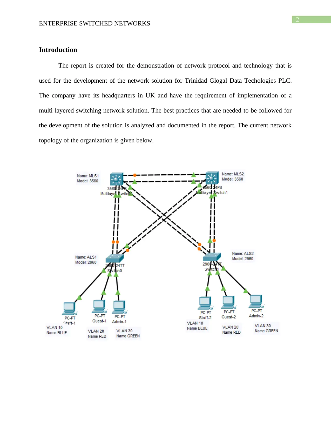
The report is created for the demonstration of network protocol and technology that is
used for the development of the network solution for Trinidad Glogal Data Techologies PLC.
The company have its headquarters in UK and have the requirement of implementation of a
multi-layered switching network solution. The best practices that are needed to be followed for
the development of the solution is analyzed and documented in the report. The current network
topology of the organization is given below.
ENTERPRISE SWITCHED NETWORKS
Introduction
The report is created for the demonstration of network protocol and technology that is
used for the development of the network solution for Trinidad Glogal Data Techologies PLC.
The company have its headquarters in UK and have the requirement of implementation of a
multi-layered switching network solution. The best practices that are needed to be followed for
the development of the solution is analyzed and documented in the report. The current network
topology of the organization is given below.
⊘ This is a preview!⊘
Do you want full access?
Subscribe today to unlock all pages.
Trusted by 1+ million students worldwide
3
ENTERPRISE SWITCHED NETWORKS
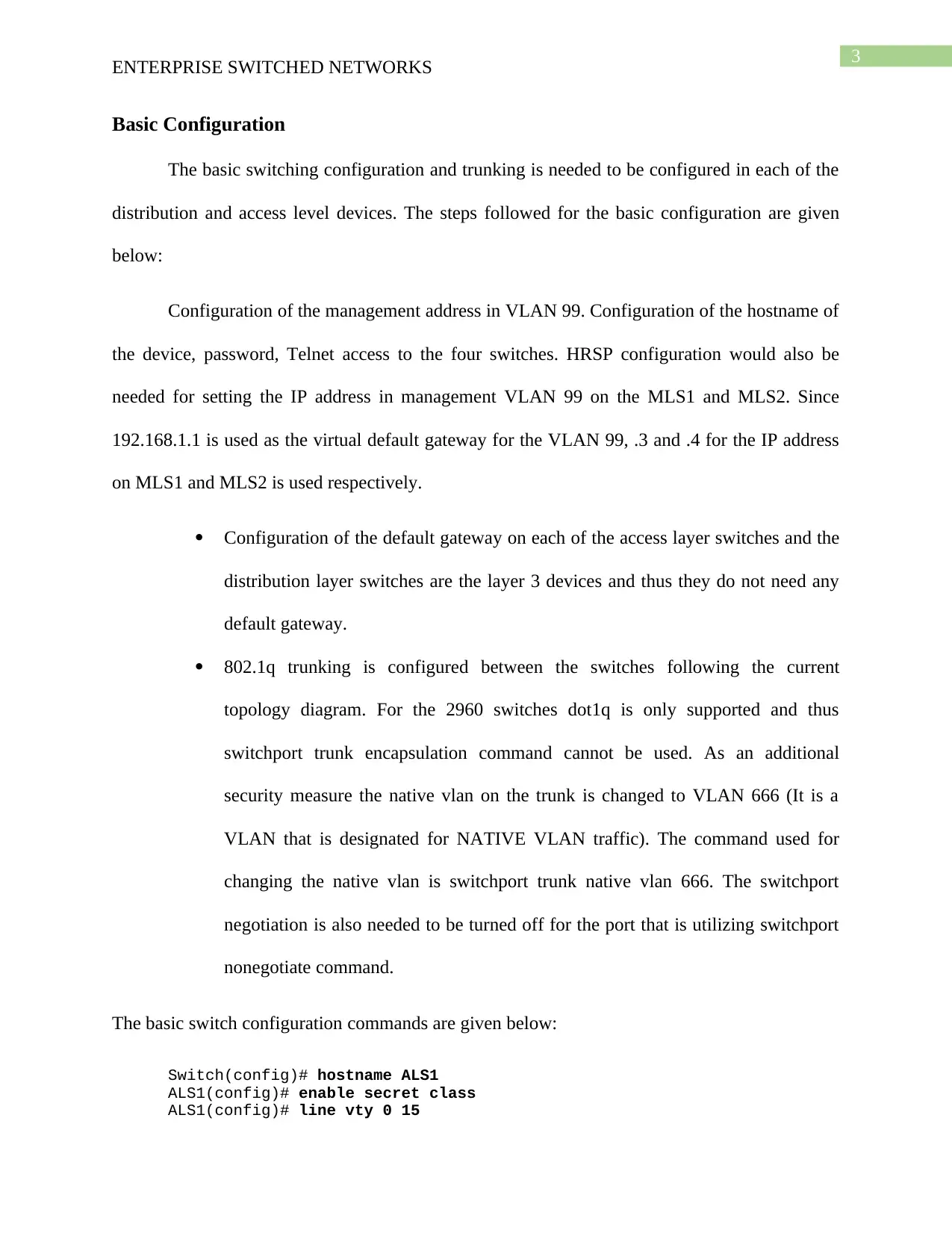
Basic Configuration
The basic switching configuration and trunking is needed to be configured in each of the
distribution and access level devices. The steps followed for the basic configuration are given
below:
Configuration of the management address in VLAN 99. Configuration of the hostname of
the device, password, Telnet access to the four switches. HRSP configuration would also be
needed for setting the IP address in management VLAN 99 on the MLS1 and MLS2. Since
192.168.1.1 is used as the virtual default gateway for the VLAN 99, .3 and .4 for the IP address
on MLS1 and MLS2 is used respectively.
Configuration of the default gateway on each of the access layer switches and the
distribution layer switches are the layer 3 devices and thus they do not need any
default gateway.
802.1q trunking is configured between the switches following the current
topology diagram. For the 2960 switches dot1q is only supported and thus
switchport trunk encapsulation command cannot be used. As an additional
security measure the native vlan on the trunk is changed to VLAN 666 (It is a
VLAN that is designated for NATIVE VLAN traffic). The command used for
changing the native vlan is switchport trunk native vlan 666. The switchport
negotiation is also needed to be turned off for the port that is utilizing switchport
nonegotiate command.
The basic switch configuration commands are given below:
Switch(config)# hostname ALS1
ALS1(config)# enable secret class
ALS1(config)# line vty 0 15
ENTERPRISE SWITCHED NETWORKS
Basic Configuration
The basic switching configuration and trunking is needed to be configured in each of the
distribution and access level devices. The steps followed for the basic configuration are given
below:
Configuration of the management address in VLAN 99. Configuration of the hostname of
the device, password, Telnet access to the four switches. HRSP configuration would also be
needed for setting the IP address in management VLAN 99 on the MLS1 and MLS2. Since
192.168.1.1 is used as the virtual default gateway for the VLAN 99, .3 and .4 for the IP address
on MLS1 and MLS2 is used respectively.
Configuration of the default gateway on each of the access layer switches and the
distribution layer switches are the layer 3 devices and thus they do not need any
default gateway.
802.1q trunking is configured between the switches following the current
topology diagram. For the 2960 switches dot1q is only supported and thus
switchport trunk encapsulation command cannot be used. As an additional
security measure the native vlan on the trunk is changed to VLAN 666 (It is a
VLAN that is designated for NATIVE VLAN traffic). The command used for
changing the native vlan is switchport trunk native vlan 666. The switchport
negotiation is also needed to be turned off for the port that is utilizing switchport
nonegotiate command.
The basic switch configuration commands are given below:
Switch(config)# hostname ALS1
ALS1(config)# enable secret class
ALS1(config)# line vty 0 15
Paraphrase This Document
Need a fresh take? Get an instant paraphrase of this document with our AI Paraphraser
4
ENTERPRISE SWITCHED NETWORKS
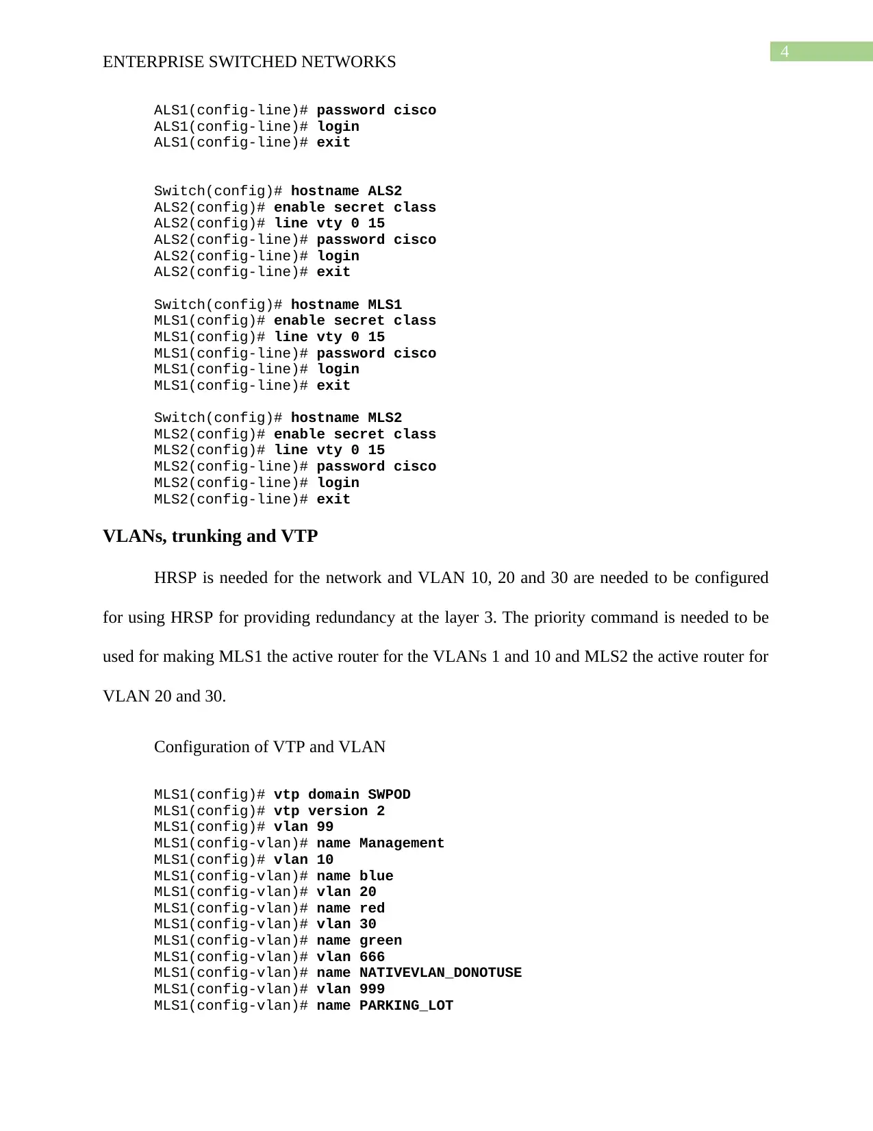
ALS1(config-line)# password cisco
ALS1(config-line)# login
ALS1(config-line)# exit
Switch(config)# hostname ALS2
ALS2(config)# enable secret class
ALS2(config)# line vty 0 15
ALS2(config-line)# password cisco
ALS2(config-line)# login
ALS2(config-line)# exit
Switch(config)# hostname MLS1
MLS1(config)# enable secret class
MLS1(config)# line vty 0 15
MLS1(config-line)# password cisco
MLS1(config-line)# login
MLS1(config-line)# exit
Switch(config)# hostname MLS2
MLS2(config)# enable secret class
MLS2(config)# line vty 0 15
MLS2(config-line)# password cisco
MLS2(config-line)# login
MLS2(config-line)# exit
VLANs, trunking and VTP
HRSP is needed for the network and VLAN 10, 20 and 30 are needed to be configured
for using HRSP for providing redundancy at the layer 3. The priority command is needed to be
used for making MLS1 the active router for the VLANs 1 and 10 and MLS2 the active router for
VLAN 20 and 30.
Configuration of VTP and VLAN
MLS1(config)# vtp domain SWPOD
MLS1(config)# vtp version 2
MLS1(config)# vlan 99
MLS1(config-vlan)# name Management
MLS1(config)# vlan 10
MLS1(config-vlan)# name blue
MLS1(config-vlan)# vlan 20
MLS1(config-vlan)# name red
MLS1(config-vlan)# vlan 30
MLS1(config-vlan)# name green
MLS1(config-vlan)# vlan 666
MLS1(config-vlan)# name NATIVEVLAN_DONOTUSE
MLS1(config-vlan)# vlan 999
MLS1(config-vlan)# name PARKING_LOT
ENTERPRISE SWITCHED NETWORKS
ALS1(config-line)# password cisco
ALS1(config-line)# login
ALS1(config-line)# exit
Switch(config)# hostname ALS2
ALS2(config)# enable secret class
ALS2(config)# line vty 0 15
ALS2(config-line)# password cisco
ALS2(config-line)# login
ALS2(config-line)# exit
Switch(config)# hostname MLS1
MLS1(config)# enable secret class
MLS1(config)# line vty 0 15
MLS1(config-line)# password cisco
MLS1(config-line)# login
MLS1(config-line)# exit
Switch(config)# hostname MLS2
MLS2(config)# enable secret class
MLS2(config)# line vty 0 15
MLS2(config-line)# password cisco
MLS2(config-line)# login
MLS2(config-line)# exit
VLANs, trunking and VTP
HRSP is needed for the network and VLAN 10, 20 and 30 are needed to be configured
for using HRSP for providing redundancy at the layer 3. The priority command is needed to be
used for making MLS1 the active router for the VLANs 1 and 10 and MLS2 the active router for
VLAN 20 and 30.
Configuration of VTP and VLAN
MLS1(config)# vtp domain SWPOD
MLS1(config)# vtp version 2
MLS1(config)# vlan 99
MLS1(config-vlan)# name Management
MLS1(config)# vlan 10
MLS1(config-vlan)# name blue
MLS1(config-vlan)# vlan 20
MLS1(config-vlan)# name red
MLS1(config-vlan)# vlan 30
MLS1(config-vlan)# name green
MLS1(config-vlan)# vlan 666
MLS1(config-vlan)# name NATIVEVLAN_DONOTUSE
MLS1(config-vlan)# vlan 999
MLS1(config-vlan)# name PARKING_LOT
5
ENTERPRISE SWITCHED NETWORKS
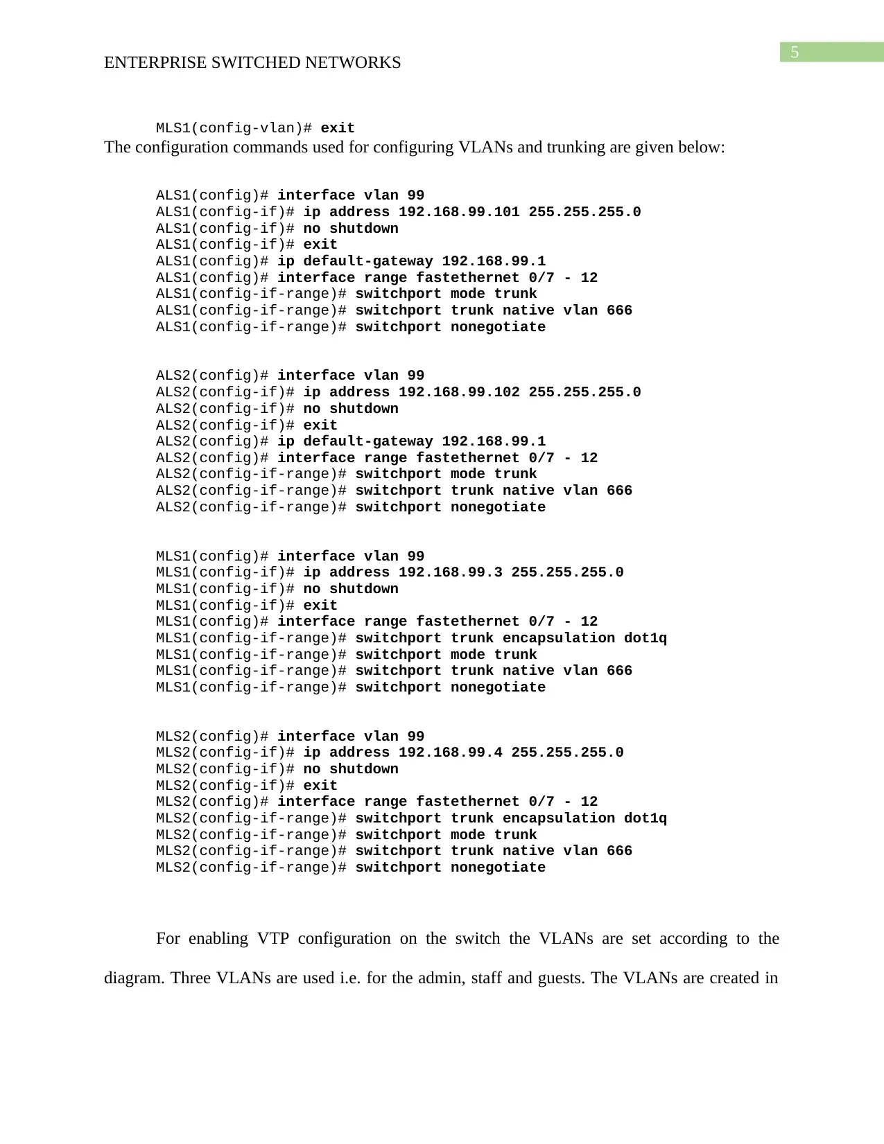
MLS1(config-vlan)# exit
The configuration commands used for configuring VLANs and trunking are given below:
ALS1(config)# interface vlan 99
ALS1(config-if)# ip address 192.168.99.101 255.255.255.0
ALS1(config-if)# no shutdown
ALS1(config-if)# exit
ALS1(config)# ip default-gateway 192.168.99.1
ALS1(config)# interface range fastethernet 0/7 - 12
ALS1(config-if-range)# switchport mode trunk
ALS1(config-if-range)# switchport trunk native vlan 666
ALS1(config-if-range)# switchport nonegotiate
ALS2(config)# interface vlan 99
ALS2(config-if)# ip address 192.168.99.102 255.255.255.0
ALS2(config-if)# no shutdown
ALS2(config-if)# exit
ALS2(config)# ip default-gateway 192.168.99.1
ALS2(config)# interface range fastethernet 0/7 - 12
ALS2(config-if-range)# switchport mode trunk
ALS2(config-if-range)# switchport trunk native vlan 666
ALS2(config-if-range)# switchport nonegotiate
MLS1(config)# interface vlan 99
MLS1(config-if)# ip address 192.168.99.3 255.255.255.0
MLS1(config-if)# no shutdown
MLS1(config-if)# exit
MLS1(config)# interface range fastethernet 0/7 - 12
MLS1(config-if-range)# switchport trunk encapsulation dot1q
MLS1(config-if-range)# switchport mode trunk
MLS1(config-if-range)# switchport trunk native vlan 666
MLS1(config-if-range)# switchport nonegotiate
MLS2(config)# interface vlan 99
MLS2(config-if)# ip address 192.168.99.4 255.255.255.0
MLS2(config-if)# no shutdown
MLS2(config-if)# exit
MLS2(config)# interface range fastethernet 0/7 - 12
MLS2(config-if-range)# switchport trunk encapsulation dot1q
MLS2(config-if-range)# switchport mode trunk
MLS2(config-if-range)# switchport trunk native vlan 666
MLS2(config-if-range)# switchport nonegotiate
For enabling VTP configuration on the switch the VLANs are set according to the
diagram. Three VLANs are used i.e. for the admin, staff and guests. The VLANs are created in
ENTERPRISE SWITCHED NETWORKS
MLS1(config-vlan)# exit
The configuration commands used for configuring VLANs and trunking are given below:
ALS1(config)# interface vlan 99
ALS1(config-if)# ip address 192.168.99.101 255.255.255.0
ALS1(config-if)# no shutdown
ALS1(config-if)# exit
ALS1(config)# ip default-gateway 192.168.99.1
ALS1(config)# interface range fastethernet 0/7 - 12
ALS1(config-if-range)# switchport mode trunk
ALS1(config-if-range)# switchport trunk native vlan 666
ALS1(config-if-range)# switchport nonegotiate
ALS2(config)# interface vlan 99
ALS2(config-if)# ip address 192.168.99.102 255.255.255.0
ALS2(config-if)# no shutdown
ALS2(config-if)# exit
ALS2(config)# ip default-gateway 192.168.99.1
ALS2(config)# interface range fastethernet 0/7 - 12
ALS2(config-if-range)# switchport mode trunk
ALS2(config-if-range)# switchport trunk native vlan 666
ALS2(config-if-range)# switchport nonegotiate
MLS1(config)# interface vlan 99
MLS1(config-if)# ip address 192.168.99.3 255.255.255.0
MLS1(config-if)# no shutdown
MLS1(config-if)# exit
MLS1(config)# interface range fastethernet 0/7 - 12
MLS1(config-if-range)# switchport trunk encapsulation dot1q
MLS1(config-if-range)# switchport mode trunk
MLS1(config-if-range)# switchport trunk native vlan 666
MLS1(config-if-range)# switchport nonegotiate
MLS2(config)# interface vlan 99
MLS2(config-if)# ip address 192.168.99.4 255.255.255.0
MLS2(config-if)# no shutdown
MLS2(config-if)# exit
MLS2(config)# interface range fastethernet 0/7 - 12
MLS2(config-if-range)# switchport trunk encapsulation dot1q
MLS2(config-if-range)# switchport mode trunk
MLS2(config-if-range)# switchport trunk native vlan 666
MLS2(config-if-range)# switchport nonegotiate
For enabling VTP configuration on the switch the VLANs are set according to the
diagram. Three VLANs are used i.e. for the admin, staff and guests. The VLANs are created in
⊘ This is a preview!⊘
Do you want full access?
Subscribe today to unlock all pages.
Trusted by 1+ million students worldwide
6
ENTERPRISE SWITCHED NETWORKS
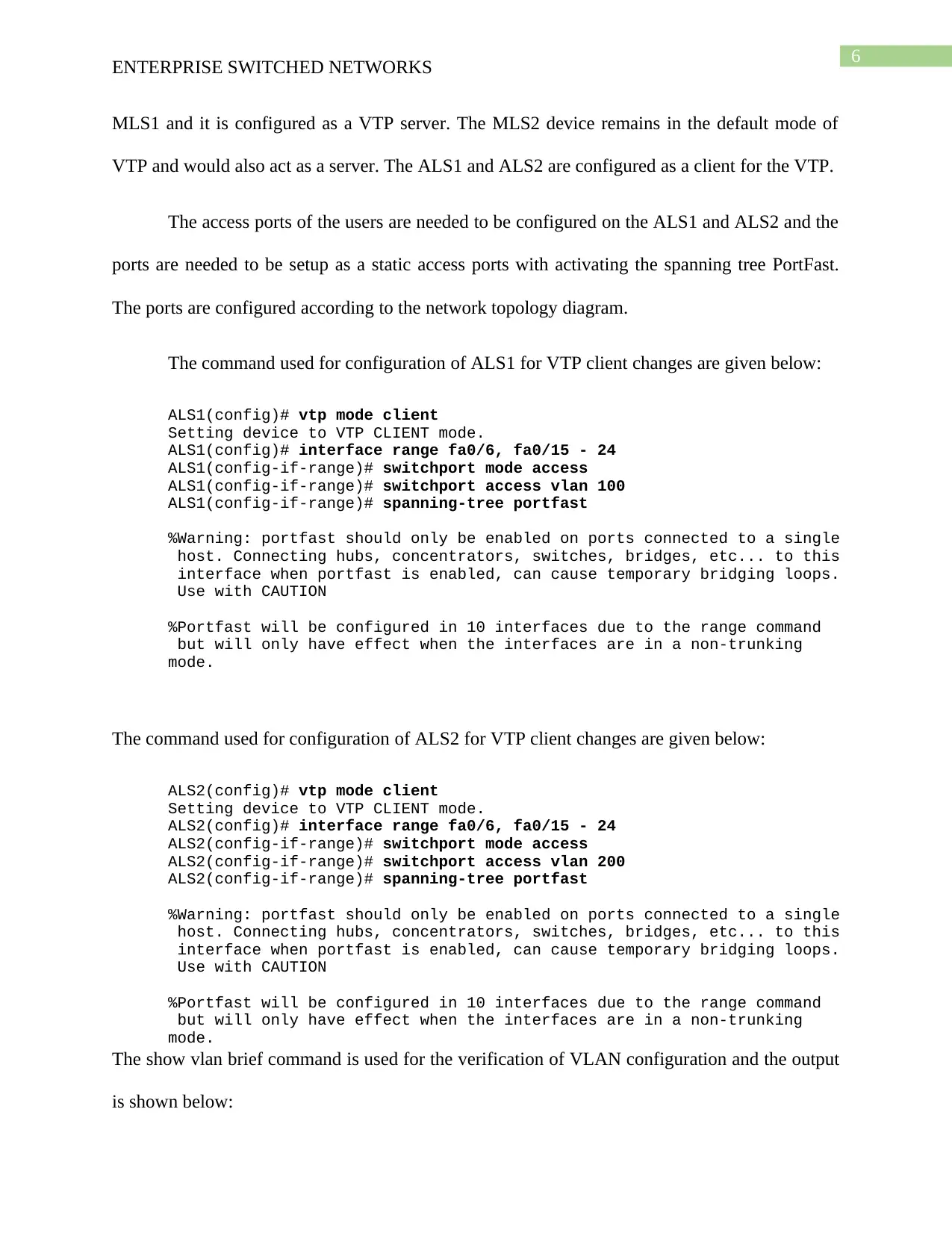
MLS1 and it is configured as a VTP server. The MLS2 device remains in the default mode of
VTP and would also act as a server. The ALS1 and ALS2 are configured as a client for the VTP.
The access ports of the users are needed to be configured on the ALS1 and ALS2 and the
ports are needed to be setup as a static access ports with activating the spanning tree PortFast.
The ports are configured according to the network topology diagram.
The command used for configuration of ALS1 for VTP client changes are given below:
ALS1(config)# vtp mode client
Setting device to VTP CLIENT mode.
ALS1(config)# interface range fa0/6, fa0/15 - 24
ALS1(config-if-range)# switchport mode access
ALS1(config-if-range)# switchport access vlan 100
ALS1(config-if-range)# spanning-tree portfast
%Warning: portfast should only be enabled on ports connected to a single
host. Connecting hubs, concentrators, switches, bridges, etc... to this
interface when portfast is enabled, can cause temporary bridging loops.
Use with CAUTION
%Portfast will be configured in 10 interfaces due to the range command
but will only have effect when the interfaces are in a non-trunking
mode.
The command used for configuration of ALS2 for VTP client changes are given below:
ALS2(config)# vtp mode client
Setting device to VTP CLIENT mode.
ALS2(config)# interface range fa0/6, fa0/15 - 24
ALS2(config-if-range)# switchport mode access
ALS2(config-if-range)# switchport access vlan 200
ALS2(config-if-range)# spanning-tree portfast
%Warning: portfast should only be enabled on ports connected to a single
host. Connecting hubs, concentrators, switches, bridges, etc... to this
interface when portfast is enabled, can cause temporary bridging loops.
Use with CAUTION
%Portfast will be configured in 10 interfaces due to the range command
but will only have effect when the interfaces are in a non-trunking
mode.
The show vlan brief command is used for the verification of VLAN configuration and the output
is shown below:
ENTERPRISE SWITCHED NETWORKS
MLS1 and it is configured as a VTP server. The MLS2 device remains in the default mode of
VTP and would also act as a server. The ALS1 and ALS2 are configured as a client for the VTP.
The access ports of the users are needed to be configured on the ALS1 and ALS2 and the
ports are needed to be setup as a static access ports with activating the spanning tree PortFast.
The ports are configured according to the network topology diagram.
The command used for configuration of ALS1 for VTP client changes are given below:
ALS1(config)# vtp mode client
Setting device to VTP CLIENT mode.
ALS1(config)# interface range fa0/6, fa0/15 - 24
ALS1(config-if-range)# switchport mode access
ALS1(config-if-range)# switchport access vlan 100
ALS1(config-if-range)# spanning-tree portfast
%Warning: portfast should only be enabled on ports connected to a single
host. Connecting hubs, concentrators, switches, bridges, etc... to this
interface when portfast is enabled, can cause temporary bridging loops.
Use with CAUTION
%Portfast will be configured in 10 interfaces due to the range command
but will only have effect when the interfaces are in a non-trunking
mode.
The command used for configuration of ALS2 for VTP client changes are given below:
ALS2(config)# vtp mode client
Setting device to VTP CLIENT mode.
ALS2(config)# interface range fa0/6, fa0/15 - 24
ALS2(config-if-range)# switchport mode access
ALS2(config-if-range)# switchport access vlan 200
ALS2(config-if-range)# spanning-tree portfast
%Warning: portfast should only be enabled on ports connected to a single
host. Connecting hubs, concentrators, switches, bridges, etc... to this
interface when portfast is enabled, can cause temporary bridging loops.
Use with CAUTION
%Portfast will be configured in 10 interfaces due to the range command
but will only have effect when the interfaces are in a non-trunking
mode.
The show vlan brief command is used for the verification of VLAN configuration and the output
is shown below:
Paraphrase This Document
Need a fresh take? Get an instant paraphrase of this document with our AI Paraphraser
7
ENTERPRISE SWITCHED NETWORKS
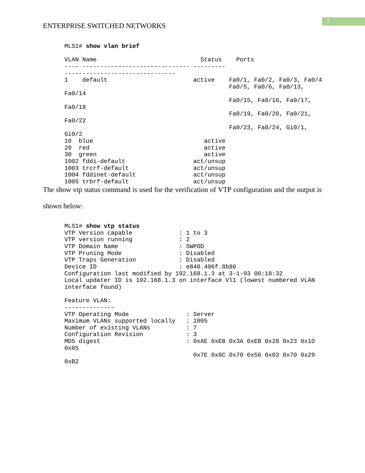
MLS1# show vlan brief
VLAN Name Status Ports
---- ------------------------------ ---------
-------------------------------
1 default active Fa0/1, Fa0/2, Fa0/3, Fa0/4
Fa0/5, Fa0/6, Fa0/13,
Fa0/14
Fa0/15, Fa0/16, Fa0/17,
Fa0/18
Fa0/19, Fa0/20, Fa0/21,
Fa0/22
Fa0/23, Fa0/24, Gi0/1,
Gi0/2
10 blue active
20 red active
30 green active
1002 fddi-default act/unsup
1003 trcrf-default act/unsup
1004 fddinet-default act/unsup
1005 trbrf-default act/unsup
The show vtp status command is used for the verification of VTP configuration and the output is
shown below:
MLS1# show vtp status
VTP Version capable : 1 to 3
VTP version running : 2
VTP Domain Name : SWPOD
VTP Pruning Mode : Disabled
VTP Traps Generation : Disabled
Device ID : e840.406f.8b80
Configuration last modified by 192.168.1.3 at 3-1-93 00:18:32
Local updater ID is 192.168.1.3 on interface Vl1 (lowest numbered VLAN
interface found)
Feature VLAN:
--------------
VTP Operating Mode : Server
Maximum VLANs supported locally : 1005
Number of existing VLANs : 7
Configuration Revision : 3
MD5 digest : 0xAE 0xEB 0x3A 0xEB 0x28 0x23 0x1D
0x85
0x7E 0x8C 0x70 0x56 0x03 0x70 0x29
0xB2
ENTERPRISE SWITCHED NETWORKS
MLS1# show vlan brief
VLAN Name Status Ports
---- ------------------------------ ---------
-------------------------------
1 default active Fa0/1, Fa0/2, Fa0/3, Fa0/4
Fa0/5, Fa0/6, Fa0/13,
Fa0/14
Fa0/15, Fa0/16, Fa0/17,
Fa0/18
Fa0/19, Fa0/20, Fa0/21,
Fa0/22
Fa0/23, Fa0/24, Gi0/1,
Gi0/2
10 blue active
20 red active
30 green active
1002 fddi-default act/unsup
1003 trcrf-default act/unsup
1004 fddinet-default act/unsup
1005 trbrf-default act/unsup
The show vtp status command is used for the verification of VTP configuration and the output is
shown below:
MLS1# show vtp status
VTP Version capable : 1 to 3
VTP version running : 2
VTP Domain Name : SWPOD
VTP Pruning Mode : Disabled
VTP Traps Generation : Disabled
Device ID : e840.406f.8b80
Configuration last modified by 192.168.1.3 at 3-1-93 00:18:32
Local updater ID is 192.168.1.3 on interface Vl1 (lowest numbered VLAN
interface found)
Feature VLAN:
--------------
VTP Operating Mode : Server
Maximum VLANs supported locally : 1005
Number of existing VLANs : 7
Configuration Revision : 3
MD5 digest : 0xAE 0xEB 0x3A 0xEB 0x28 0x23 0x1D
0x85
0x7E 0x8C 0x70 0x56 0x03 0x70 0x29
0xB2
8
ENTERPRISE SWITCHED NETWORKS
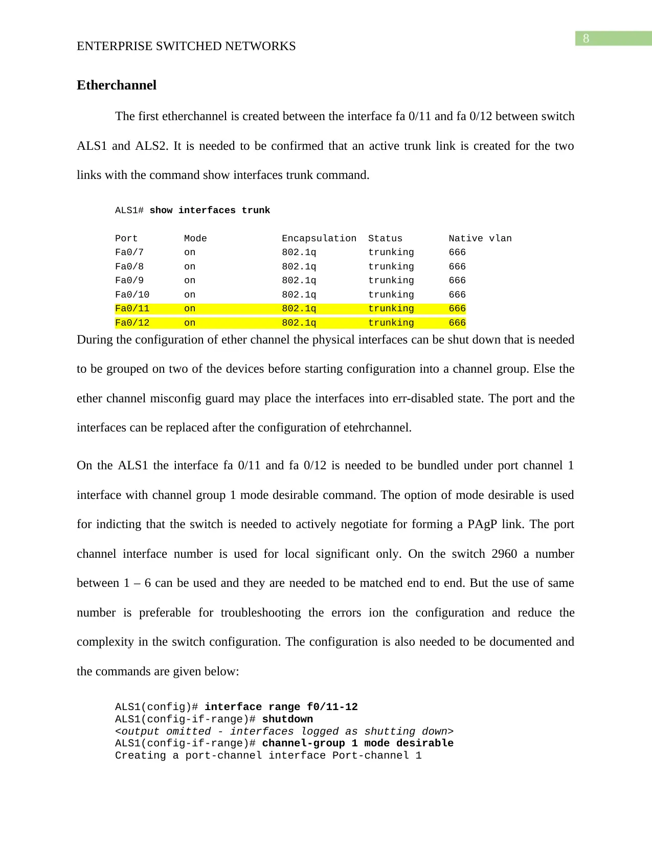
Etherchannel
The first etherchannel is created between the interface fa 0/11 and fa 0/12 between switch
ALS1 and ALS2. It is needed to be confirmed that an active trunk link is created for the two
links with the command show interfaces trunk command.
ALS1# show interfaces trunk
Port Mode Encapsulation Status Native vlan
Fa0/7 on 802.1q trunking 666
Fa0/8 on 802.1q trunking 666
Fa0/9 on 802.1q trunking 666
Fa0/10 on 802.1q trunking 666
Fa0/11 on 802.1q trunking 666
Fa0/12 on 802.1q trunking 666
During the configuration of ether channel the physical interfaces can be shut down that is needed
to be grouped on two of the devices before starting configuration into a channel group. Else the
ether channel misconfig guard may place the interfaces into err-disabled state. The port and the
interfaces can be replaced after the configuration of etehrchannel.
On the ALS1 the interface fa 0/11 and fa 0/12 is needed to be bundled under port channel 1
interface with channel group 1 mode desirable command. The option of mode desirable is used
for indicting that the switch is needed to actively negotiate for forming a PAgP link. The port
channel interface number is used for local significant only. On the switch 2960 a number
between 1 – 6 can be used and they are needed to be matched end to end. But the use of same
number is preferable for troubleshooting the errors ion the configuration and reduce the
complexity in the switch configuration. The configuration is also needed to be documented and
the commands are given below:
ALS1(config)# interface range f0/11-12
ALS1(config-if-range)# shutdown
<output omitted - interfaces logged as shutting down>
ALS1(config-if-range)# channel-group 1 mode desirable
Creating a port-channel interface Port-channel 1
ENTERPRISE SWITCHED NETWORKS
Etherchannel
The first etherchannel is created between the interface fa 0/11 and fa 0/12 between switch
ALS1 and ALS2. It is needed to be confirmed that an active trunk link is created for the two
links with the command show interfaces trunk command.
ALS1# show interfaces trunk
Port Mode Encapsulation Status Native vlan
Fa0/7 on 802.1q trunking 666
Fa0/8 on 802.1q trunking 666
Fa0/9 on 802.1q trunking 666
Fa0/10 on 802.1q trunking 666
Fa0/11 on 802.1q trunking 666
Fa0/12 on 802.1q trunking 666
During the configuration of ether channel the physical interfaces can be shut down that is needed
to be grouped on two of the devices before starting configuration into a channel group. Else the
ether channel misconfig guard may place the interfaces into err-disabled state. The port and the
interfaces can be replaced after the configuration of etehrchannel.
On the ALS1 the interface fa 0/11 and fa 0/12 is needed to be bundled under port channel 1
interface with channel group 1 mode desirable command. The option of mode desirable is used
for indicting that the switch is needed to actively negotiate for forming a PAgP link. The port
channel interface number is used for local significant only. On the switch 2960 a number
between 1 – 6 can be used and they are needed to be matched end to end. But the use of same
number is preferable for troubleshooting the errors ion the configuration and reduce the
complexity in the switch configuration. The configuration is also needed to be documented and
the commands are given below:
ALS1(config)# interface range f0/11-12
ALS1(config-if-range)# shutdown
<output omitted - interfaces logged as shutting down>
ALS1(config-if-range)# channel-group 1 mode desirable
Creating a port-channel interface Port-channel 1
⊘ This is a preview!⊘
Do you want full access?
Subscribe today to unlock all pages.
Trusted by 1+ million students worldwide
9
ENTERPRISE SWITCHED NETWORKS
ALS1(config-if-range)# no shutdown
<output omitted - interfaces logged as coming up>
ALS1(config-if-range)# exit
ALS1(config)#
<the following output is seen after ALS2 configuration is complete>
*Mar 1 00:14:01.570: %LINK-3-UPDOWN: Interface Port-channel1, changed
state to up
*Mar 1 00:14:02.576: %LINEPROTO-5-UPDOWN: Line protocol on Interface
Port-channel1, changed state to up
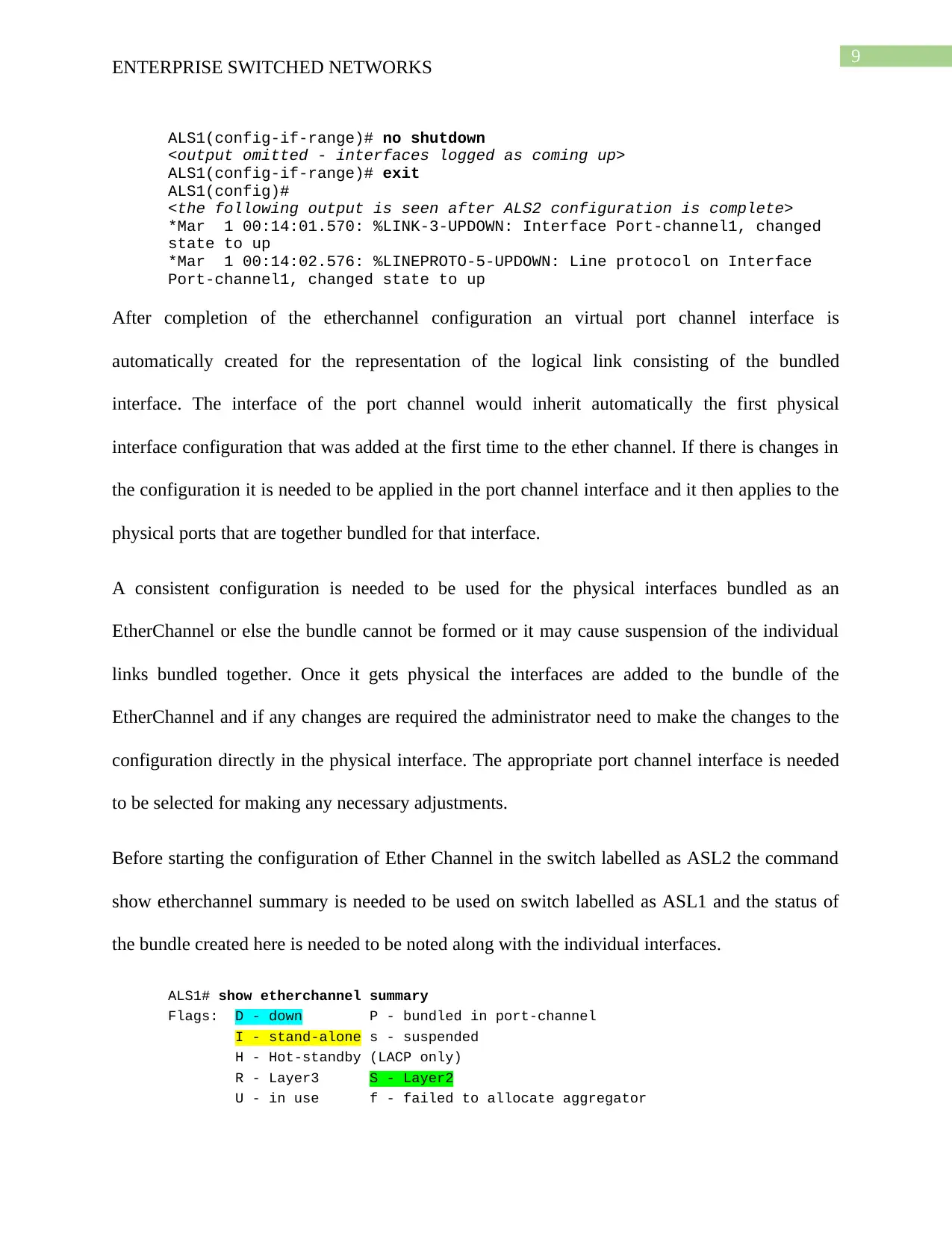
After completion of the etherchannel configuration an virtual port channel interface is
automatically created for the representation of the logical link consisting of the bundled
interface. The interface of the port channel would inherit automatically the first physical
interface configuration that was added at the first time to the ether channel. If there is changes in
the configuration it is needed to be applied in the port channel interface and it then applies to the
physical ports that are together bundled for that interface.
A consistent configuration is needed to be used for the physical interfaces bundled as an
EtherChannel or else the bundle cannot be formed or it may cause suspension of the individual
links bundled together. Once it gets physical the interfaces are added to the bundle of the
EtherChannel and if any changes are required the administrator need to make the changes to the
configuration directly in the physical interface. The appropriate port channel interface is needed
to be selected for making any necessary adjustments.
Before starting the configuration of Ether Channel in the switch labelled as ASL2 the command
show etherchannel summary is needed to be used on switch labelled as ASL1 and the status of
the bundle created here is needed to be noted along with the individual interfaces.
ALS1# show etherchannel summary
Flags: D - down P - bundled in port-channel
I - stand-alone s - suspended
H - Hot-standby (LACP only)
R - Layer3 S - Layer2
U - in use f - failed to allocate aggregator
ENTERPRISE SWITCHED NETWORKS
ALS1(config-if-range)# no shutdown
<output omitted - interfaces logged as coming up>
ALS1(config-if-range)# exit
ALS1(config)#
<the following output is seen after ALS2 configuration is complete>
*Mar 1 00:14:01.570: %LINK-3-UPDOWN: Interface Port-channel1, changed
state to up
*Mar 1 00:14:02.576: %LINEPROTO-5-UPDOWN: Line protocol on Interface
Port-channel1, changed state to up
After completion of the etherchannel configuration an virtual port channel interface is
automatically created for the representation of the logical link consisting of the bundled
interface. The interface of the port channel would inherit automatically the first physical
interface configuration that was added at the first time to the ether channel. If there is changes in
the configuration it is needed to be applied in the port channel interface and it then applies to the
physical ports that are together bundled for that interface.
A consistent configuration is needed to be used for the physical interfaces bundled as an
EtherChannel or else the bundle cannot be formed or it may cause suspension of the individual
links bundled together. Once it gets physical the interfaces are added to the bundle of the
EtherChannel and if any changes are required the administrator need to make the changes to the
configuration directly in the physical interface. The appropriate port channel interface is needed
to be selected for making any necessary adjustments.
Before starting the configuration of Ether Channel in the switch labelled as ASL2 the command
show etherchannel summary is needed to be used on switch labelled as ASL1 and the status of
the bundle created here is needed to be noted along with the individual interfaces.
ALS1# show etherchannel summary
Flags: D - down P - bundled in port-channel
I - stand-alone s - suspended
H - Hot-standby (LACP only)
R - Layer3 S - Layer2
U - in use f - failed to allocate aggregator
Paraphrase This Document
Need a fresh take? Get an instant paraphrase of this document with our AI Paraphraser
10
ENTERPRISE SWITCHED NETWORKS
M - not in use, minimum links not met
u - unsuitable for bundling
w - waiting to be aggregated
d - default port
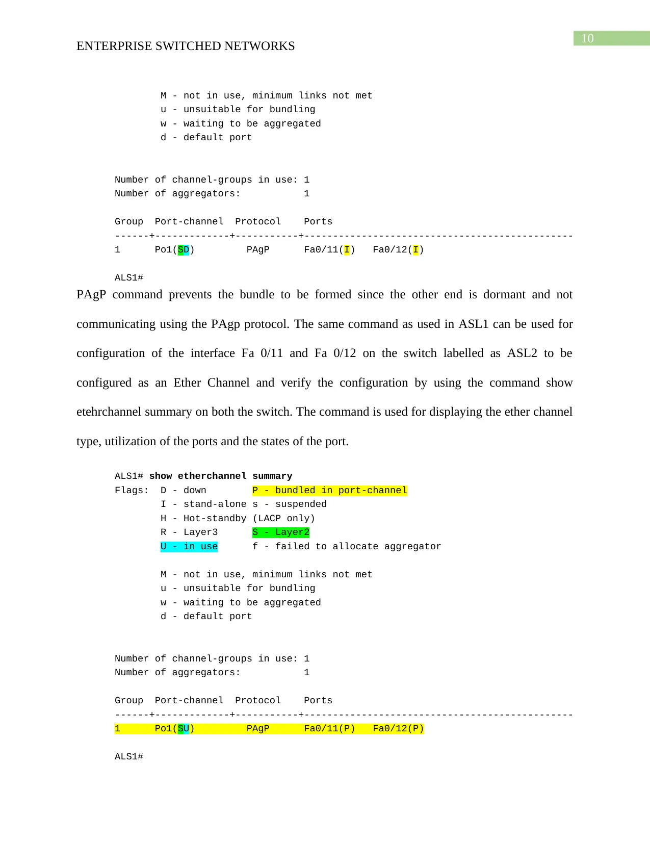
Number of channel-groups in use: 1
Number of aggregators: 1
Group Port-channel Protocol Ports
------+-------------+-----------+-----------------------------------------------
1 Po1(SD) PAgP Fa0/11(I) Fa0/12(I)
ALS1#
PAgP command prevents the bundle to be formed since the other end is dormant and not
communicating using the PAgp protocol. The same command as used in ASL1 can be used for
configuration of the interface Fa 0/11 and Fa 0/12 on the switch labelled as ASL2 to be
configured as an Ether Channel and verify the configuration by using the command show
etehrchannel summary on both the switch. The command is used for displaying the ether channel
type, utilization of the ports and the states of the port.
ALS1# show etherchannel summary
Flags: D - down P - bundled in port-channel
I - stand-alone s - suspended
H - Hot-standby (LACP only)
R - Layer3 S - Layer2
U - in use f - failed to allocate aggregator
M - not in use, minimum links not met
u - unsuitable for bundling
w - waiting to be aggregated
d - default port
Number of channel-groups in use: 1
Number of aggregators: 1
Group Port-channel Protocol Ports
------+-------------+-----------+-----------------------------------------------
1 Po1(SU) PAgP Fa0/11(P) Fa0/12(P)
ALS1#
ENTERPRISE SWITCHED NETWORKS
M - not in use, minimum links not met
u - unsuitable for bundling
w - waiting to be aggregated
d - default port
Number of channel-groups in use: 1
Number of aggregators: 1
Group Port-channel Protocol Ports
------+-------------+-----------+-----------------------------------------------
1 Po1(SD) PAgP Fa0/11(I) Fa0/12(I)
ALS1#
PAgP command prevents the bundle to be formed since the other end is dormant and not
communicating using the PAgp protocol. The same command as used in ASL1 can be used for
configuration of the interface Fa 0/11 and Fa 0/12 on the switch labelled as ASL2 to be
configured as an Ether Channel and verify the configuration by using the command show
etehrchannel summary on both the switch. The command is used for displaying the ether channel
type, utilization of the ports and the states of the port.
ALS1# show etherchannel summary
Flags: D - down P - bundled in port-channel
I - stand-alone s - suspended
H - Hot-standby (LACP only)
R - Layer3 S - Layer2
U - in use f - failed to allocate aggregator
M - not in use, minimum links not met
u - unsuitable for bundling
w - waiting to be aggregated
d - default port
Number of channel-groups in use: 1
Number of aggregators: 1
Group Port-channel Protocol Ports
------+-------------+-----------+-----------------------------------------------
1 Po1(SU) PAgP Fa0/11(P) Fa0/12(P)
ALS1#
11
ENTERPRISE SWITCHED NETWORKS
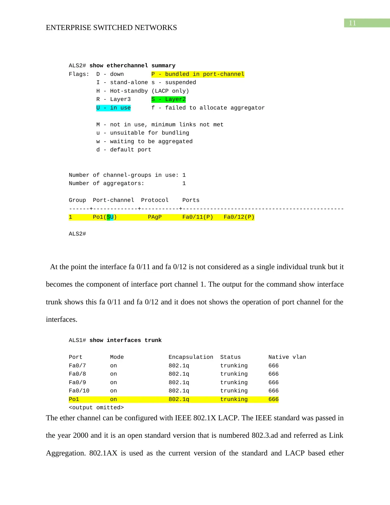
ALS2# show etherchannel summary
Flags: D - down P - bundled in port-channel
I - stand-alone s - suspended
H - Hot-standby (LACP only)
R - Layer3 S - Layer2
U - in use f - failed to allocate aggregator
M - not in use, minimum links not met
u - unsuitable for bundling
w - waiting to be aggregated
d - default port
Number of channel-groups in use: 1
Number of aggregators: 1
Group Port-channel Protocol Ports
------+-------------+-----------+-----------------------------------------------
1 Po1(SU) PAgP Fa0/11(P) Fa0/12(P)
ALS2#
At the point the interface fa 0/11 and fa 0/12 is not considered as a single individual trunk but it
becomes the component of interface port channel 1. The output for the command show interface
trunk shows this fa 0/11 and fa 0/12 and it does not shows the operation of port channel for the
interfaces.
ALS1# show interfaces trunk
Port Mode Encapsulation Status Native vlan
Fa0/7 on 802.1q trunking 666
Fa0/8 on 802.1q trunking 666
Fa0/9 on 802.1q trunking 666
Fa0/10 on 802.1q trunking 666
Po1 on 802.1q trunking 666
<output omitted>
The ether channel can be configured with IEEE 802.1X LACP. The IEEE standard was passed in
the year 2000 and it is an open standard version that is numbered 802.3.ad and referred as Link
Aggregation. 802.1AX is used as the current version of the standard and LACP based ether
ENTERPRISE SWITCHED NETWORKS
ALS2# show etherchannel summary
Flags: D - down P - bundled in port-channel
I - stand-alone s - suspended
H - Hot-standby (LACP only)
R - Layer3 S - Layer2
U - in use f - failed to allocate aggregator
M - not in use, minimum links not met
u - unsuitable for bundling
w - waiting to be aggregated
d - default port
Number of channel-groups in use: 1
Number of aggregators: 1
Group Port-channel Protocol Ports
------+-------------+-----------+-----------------------------------------------
1 Po1(SU) PAgP Fa0/11(P) Fa0/12(P)
ALS2#
At the point the interface fa 0/11 and fa 0/12 is not considered as a single individual trunk but it
becomes the component of interface port channel 1. The output for the command show interface
trunk shows this fa 0/11 and fa 0/12 and it does not shows the operation of port channel for the
interfaces.
ALS1# show interfaces trunk
Port Mode Encapsulation Status Native vlan
Fa0/7 on 802.1q trunking 666
Fa0/8 on 802.1q trunking 666
Fa0/9 on 802.1q trunking 666
Fa0/10 on 802.1q trunking 666
Po1 on 802.1q trunking 666
<output omitted>
The ether channel can be configured with IEEE 802.1X LACP. The IEEE standard was passed in
the year 2000 and it is an open standard version that is numbered 802.3.ad and referred as Link
Aggregation. 802.1AX is used as the current version of the standard and LACP based ether
⊘ This is a preview!⊘
Do you want full access?
Subscribe today to unlock all pages.
Trusted by 1+ million students worldwide
1 out of 32
Related Documents


Your All-in-One AI-Powered Toolkit for Academic Success.
+13062052269
info@desklib.com
Available 24*7 on WhatsApp / Email
![[object Object]](/_next/static/media/star-bottom.7253800d.svg)
Unlock your academic potential
Copyright © 2020–2026 A2Z Services. All Rights Reserved. Developed and managed by ZUCOL.