U22011 Structural Integrity Coursework: Fan Blade & Piping Analysis
VerifiedAdded on 2022/08/22
|21
|4028
|13
Report
AI Summary
This report presents a structural integrity assessment, divided into two parts. Part A focuses on the damage tolerance analysis of an aero-engine fan blade made of Ti-6Al-4V alloy, employing fracture mechanics principles to evaluate potential failure causes under various stress conditions, including fatigue crack growth predictions using the Paris law. Part B investigates the life assessment of a steam power plant header piping system, emphasizing creep as the primary life-limiting factor for low-alloyed ferritic steels at high temperatures. The report explores both post-service examination and operational parameter approaches for creep life prediction, examining the effects of material properties and operational stresses on component lifespan. The analysis includes calculations, discussions, and conclusions regarding inspection schedules and the importance of damage tolerance analysis for ensuring the safety and reliability of aircraft and power plant components. The report emphasizes the importance of material selection, inspection frequency, and the application of fracture mechanics and creep analysis in engineering design and maintenance.
Surname 1
Student Name
Professors Name
Course Title
Date
Part A: Fan Blade Damage Tolerance Analysis.
INTRODUCTION
Aircraft components are usually made of super-alloys with outstanding strengths to improve their
reliability during the service operation. However, different factors affect the life of these
components, such as service-induced degradation and material defects during manufacturing.
The fan blades of an aero-engine have severe operating conditions that influence their life. They
undergo high mechanical stresses from vibratory, centrifugal, and flexural stresses and high
thermal stresses from the high temperature in their operating environment [1].
Damage tolerance analysis must be performed to identify the possible causes of fan-blade failure.
Metallurgical examinations and mechanical analyses are both integrated in investigating the
aero-engine fan blade damage tolerance. The low-cyclic fatigue (LCF) and high-cyclic fatigue
(HCF) damages are considered in combination during structural integrity assessment of the fan
blades. This paper emphasizes on the analytical analysis of aero-engine’s fan blades made of Ti-
6Al-4V alloy by the use of fracture mechanics analysis principles [2].
Paraphrase This Document
Need a fresh take? Get an instant paraphrase of this document with our AI Paraphraser
Surname 2
LITERATURE REVIEW
Metals exhibit damage when subjected to repeated cyclic-loading due to fatigue. The stress
magnitudes in a single load cycle may not be sufficient to cause material failure. However,
repeated cyclic loading ultimately leads to a fatigue failure. Crack initiation, followed by its
propagation under operating load, may lead to rupture when the crack exceeds a critical crack
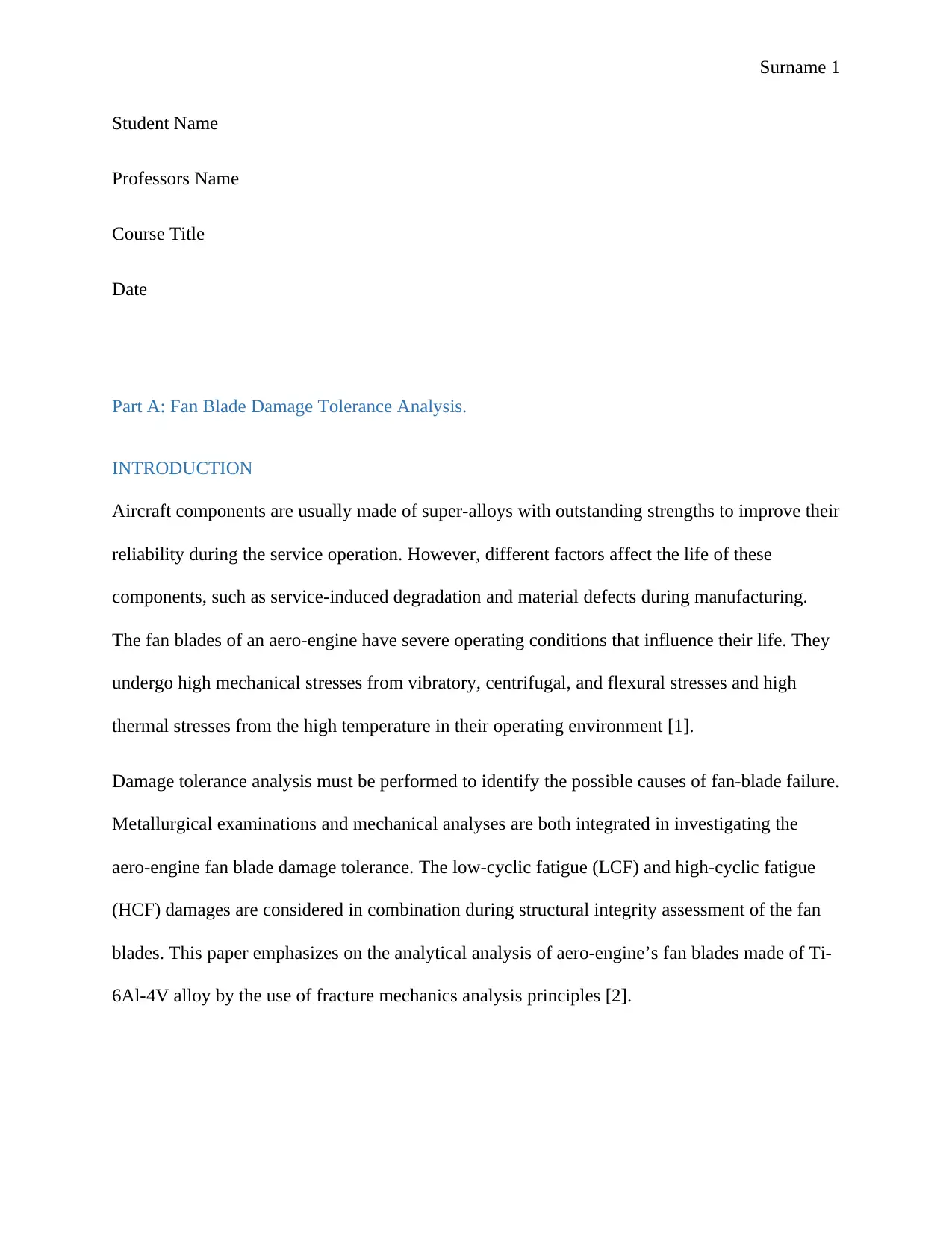
size [3]. Aircraft components operate under variable amplitude load cycles resulting from the
changing and unpredictable wind speed and directions. Figure 1.1 presents important fatigue
terms of common types of load cycles [4].
Figure 1.1: Specification of the load cycle.
Fan blades in aero-engines
Fan blades undergo considerable mechanical and thermal loading. They are crucial components
of the aero-engine that affect the engine’s performance and reliability. Damage tolerance
LITERATURE REVIEW
Metals exhibit damage when subjected to repeated cyclic-loading due to fatigue. The stress
magnitudes in a single load cycle may not be sufficient to cause material failure. However,
repeated cyclic loading ultimately leads to a fatigue failure. Crack initiation, followed by its
propagation under operating load, may lead to rupture when the crack exceeds a critical crack
size [3]. Aircraft components operate under variable amplitude load cycles resulting from the
changing and unpredictable wind speed and directions. Figure 1.1 presents important fatigue
terms of common types of load cycles [4].
Figure 1.1: Specification of the load cycle.
Fan blades in aero-engines
Fan blades undergo considerable mechanical and thermal loading. They are crucial components
of the aero-engine that affect the engine’s performance and reliability. Damage tolerance
Surname 3
analysis of the fan blades has been the focus of research works since a fan blade failure can cause
a puncture to the engine and consequently affect the performance and safety of the aircraft [8].
The common failures in fan blades of aero-engines are due to mechanical damage, damage due
to high-temperature exposure, and creep failures. More profound knowledge and understanding
are gained on the damage tolerance of the fan blades through investigations of the crack
initiation and propagation mechanisms. High Cyclic fatigue (HCF) and Low Cycle fatigue (LCF)
failures often occur in the rotating parts, such as the fan blades [9].
Effects of small defects on fatigue thresholds.
In fracture mechanics, defects in the material are considered in structural integrity assessment.
Determination of the strain release rate and the stress integrity factor is possible from the
knowledge of applied stress and the different sizes of the defects. The most commonly used
fracture mechanics method is the linear elastic fracture mechanics (LEFM), which is based on
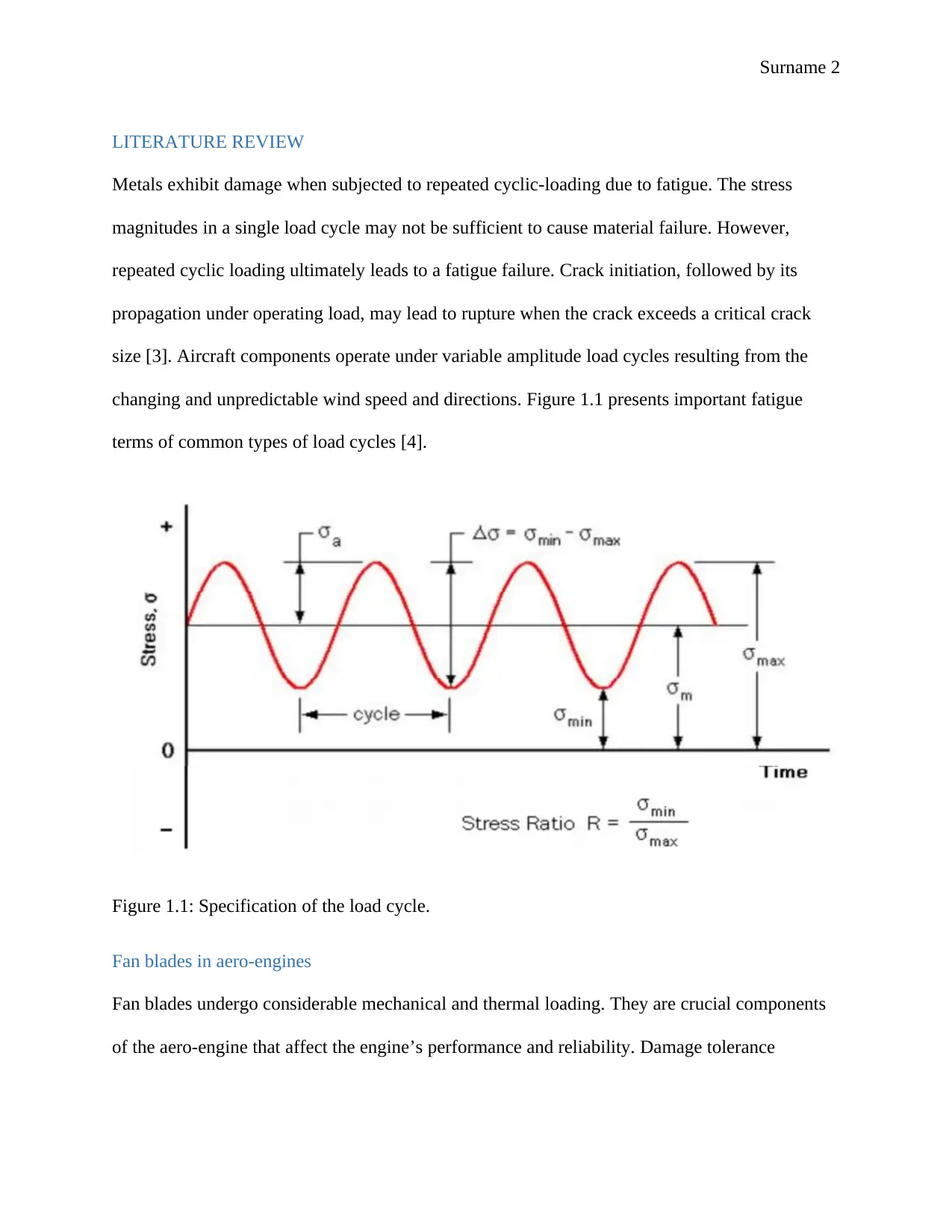
Griffin’s theory of fracture [10]. Fatigue failure stages are initiation of crack, propagation of
crack growth, and, finally, catastrophic fracture. The reduction in fatigue limit as a result of
increase in the defect size of the crack is shown in figure 1.1 [11].
Figure 1.2: Fatigue versus defect size on log-log paper
analysis of the fan blades has been the focus of research works since a fan blade failure can cause
a puncture to the engine and consequently affect the performance and safety of the aircraft [8].
The common failures in fan blades of aero-engines are due to mechanical damage, damage due
to high-temperature exposure, and creep failures. More profound knowledge and understanding
are gained on the damage tolerance of the fan blades through investigations of the crack
initiation and propagation mechanisms. High Cyclic fatigue (HCF) and Low Cycle fatigue (LCF)
failures often occur in the rotating parts, such as the fan blades [9].
Effects of small defects on fatigue thresholds.
In fracture mechanics, defects in the material are considered in structural integrity assessment.
Determination of the strain release rate and the stress integrity factor is possible from the
knowledge of applied stress and the different sizes of the defects. The most commonly used
fracture mechanics method is the linear elastic fracture mechanics (LEFM), which is based on
Griffin’s theory of fracture [10]. Fatigue failure stages are initiation of crack, propagation of
crack growth, and, finally, catastrophic fracture. The reduction in fatigue limit as a result of
increase in the defect size of the crack is shown in figure 1.1 [11].
Figure 1.2: Fatigue versus defect size on log-log paper
⊘ This is a preview!⊘
Do you want full access?
Subscribe today to unlock all pages.
Trusted by 1+ million students worldwide
Surname 4
METHODS
Damage tolerance analysis is used to devise inspection schedules based on the following criteria:
i. The assumed initial damage condition of the fan blade which in this case is assumed
as a center-cracked plate [12]
ii. The fatigue and maximum operational stresses in the fan blade that cause crack
growth from the assumed damaged condition. The fan blade is considered to
experience a uniformly distributed tensile stress.
iii. The fan blade geometry.
iv. Critical crack size beyond which catastrophic failure occurs.
v. Acceptable level of risk [13]
Material properties and fatigue calculations
The Ti-6Al-4V alloy is composed of Ti (89.137 wt%), Al(6.30 %), Fe(0.19 %), N(0.013 %),
O(0.19 %) and V(4.17 %). From the ASM material datasheet, Ti6-4 has a fatigue strength of 240
MPa at stress concentration factor of Kt=5.3. Considering that the blade is modelled as a
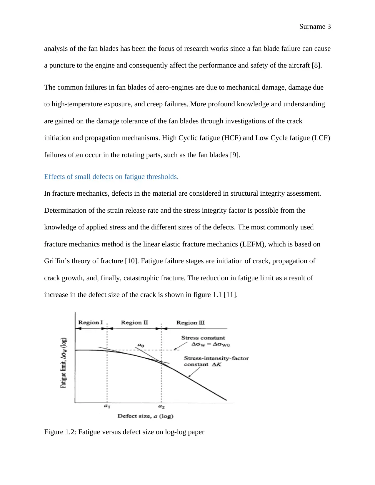
rectangular plate of width, W equals 500mm and defect size, 2a of 0.5mm, the following stress
calculations can be made [14].
Maximum stress acting on the blade:
σ =σ d ± σb
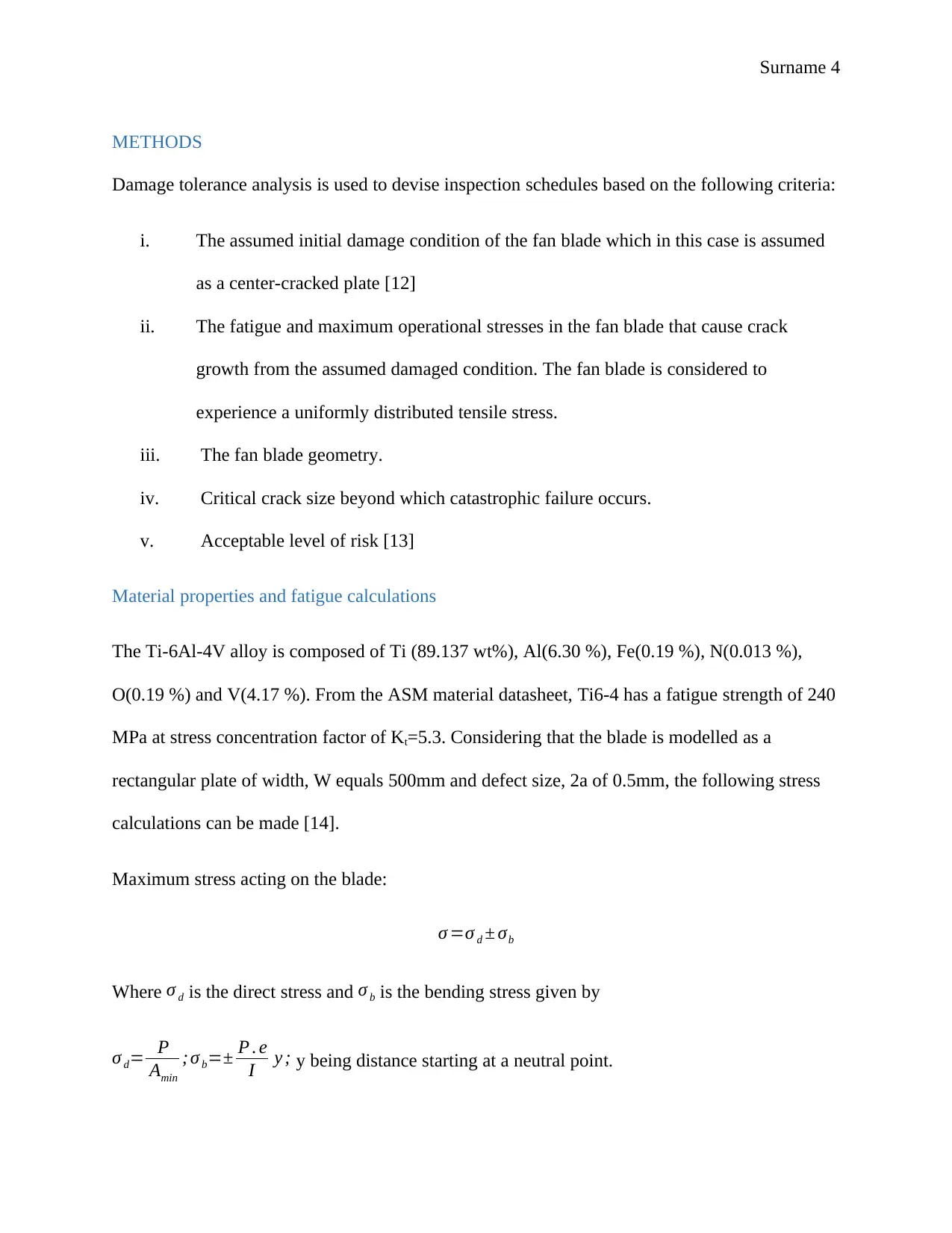
Where σ d is the direct stress and σ b is the bending stress given by
σ d= P
Amin
; σ b=± P . e
I y ; y being distance starting at a neutral point.
METHODS
Damage tolerance analysis is used to devise inspection schedules based on the following criteria:
i. The assumed initial damage condition of the fan blade which in this case is assumed
as a center-cracked plate [12]
ii. The fatigue and maximum operational stresses in the fan blade that cause crack
growth from the assumed damaged condition. The fan blade is considered to
experience a uniformly distributed tensile stress.
iii. The fan blade geometry.
iv. Critical crack size beyond which catastrophic failure occurs.
v. Acceptable level of risk [13]
Material properties and fatigue calculations
The Ti-6Al-4V alloy is composed of Ti (89.137 wt%), Al(6.30 %), Fe(0.19 %), N(0.013 %),
O(0.19 %) and V(4.17 %). From the ASM material datasheet, Ti6-4 has a fatigue strength of 240
MPa at stress concentration factor of Kt=5.3. Considering that the blade is modelled as a
rectangular plate of width, W equals 500mm and defect size, 2a of 0.5mm, the following stress
calculations can be made [14].
Maximum stress acting on the blade:
σ =σ d ± σb
Where σ d is the direct stress and σ b is the bending stress given by
σ d= P
Amin
; σ b=± P . e
I y ; y being distance starting at a neutral point.
Paraphrase This Document
Need a fresh take? Get an instant paraphrase of this document with our AI Paraphraser
Surname 5
Amin=W × a=500 × 0.5
2 =125 m m2 from the given dimensions [15].
y
I = 60
W 2 t = 60
5002 × 0.5
2
=9.6 ×10⁻⁴
for Ti-6Al-4V alloy.
Assuming a load of P=5 kN, the direct and the bending stress can be calculated as:
σ d= 5000
125 =40 MPa
And
σ b=± P. e ( y
I )= (5000 × 0.25 ) × 9.6 ×10−4=1.2 MPa
σ =40+1.2=41.2 MPa
Since the blade is considered to be center-cracked, high stress concentrations exist near the
notch. Maximum stress at the notch is obtained from the acting stress on the fan blade and the
stress concentration factor, Kt [16].
σ max=kt σ
σ max=5.3 × 41.2=218.36 MPa
The alternating stress, sn is given by:
sn=a Nb
Where a and b are constants for the Ti-6Al-4V alloy and N are the cycles number.
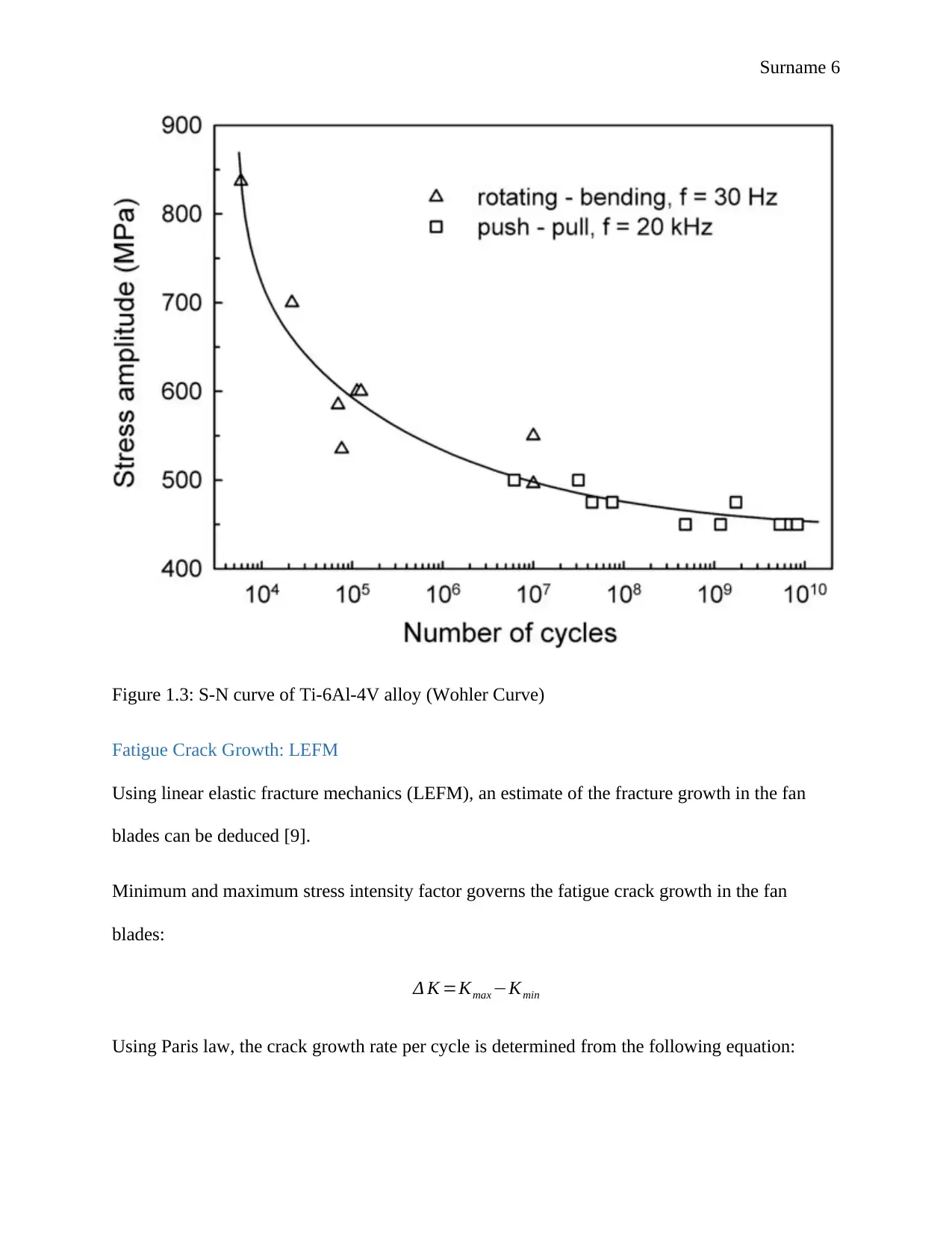
The figure 1.3 below shows the curve of stress against number of cycles for Ti6-4 material used.
Amin=W × a=500 × 0.5
2 =125 m m2 from the given dimensions [15].
y
I = 60
W 2 t = 60
5002 × 0.5
2
=9.6 ×10⁻⁴
for Ti-6Al-4V alloy.
Assuming a load of P=5 kN, the direct and the bending stress can be calculated as:
σ d= 5000
125 =40 MPa
And
σ b=± P. e ( y
I )= (5000 × 0.25 ) × 9.6 ×10−4=1.2 MPa
σ =40+1.2=41.2 MPa
Since the blade is considered to be center-cracked, high stress concentrations exist near the
notch. Maximum stress at the notch is obtained from the acting stress on the fan blade and the
stress concentration factor, Kt [16].
σ max=kt σ
σ max=5.3 × 41.2=218.36 MPa
The alternating stress, sn is given by:
sn=a Nb
Where a and b are constants for the Ti-6Al-4V alloy and N are the cycles number.
The figure 1.3 below shows the curve of stress against number of cycles for Ti6-4 material used.
Surname 6
Figure 1.3: S-N curve of Ti-6Al-4V alloy (Wohler Curve)
Fatigue Crack Growth: LEFM
Using linear elastic fracture mechanics (LEFM), an estimate of the fracture growth in the fan
blades can be deduced [9].
Minimum and maximum stress intensity factor governs the fatigue crack growth in the fan
blades:
Δ K =Kmax −Kmin
Using Paris law, the crack growth rate per cycle is determined from the following equation:
⊘ This is a preview!⊘
Do you want full access?
Subscribe today to unlock all pages.
Trusted by 1+ million students worldwide
Surname 7
da
dN =C ( Δ K )m
Where the Paris law parameters (C, m) are unique for any particular material.
ANALYSIS
From the methodology, the maximum stress that the fan blade with the provided dimensions is
subjected to is 218.36 MPa assuming a combined load contribution of 5 kN from the vibrational
and centrifugal forces. An operational cyclic stress range of -30 to 220 MPa will cause a fatigue
fracture growth in the fan blade since its maximum stress falls within this range. Increasing the
maximum stress by 50% means [2]:
New maximum stress=1.5× 218.36=327.54 MPa
With the same stress range, fatigue crack growth occurs much faster since 327.54 MPa is much
higher than the cyclic stress range.
If the fan blade sustains a 5 times overload of the nominal stress, the following calculations can
be made [8]:
P=5 × 5000=25000 N
σ d= 25000
125 =200 MPa
And σ b=± P. e ( y
I )= (25000 × 0.25 ) × 9.6 ×10−4=6 MPa
σ =200+6=206 MPa σ max=5.3 × 206=1091.8 MPa
The component will not be strong enough to sustain a 5-times overload.
Paraphrase This Document
Need a fresh take? Get an instant paraphrase of this document with our AI Paraphraser
Surname 8
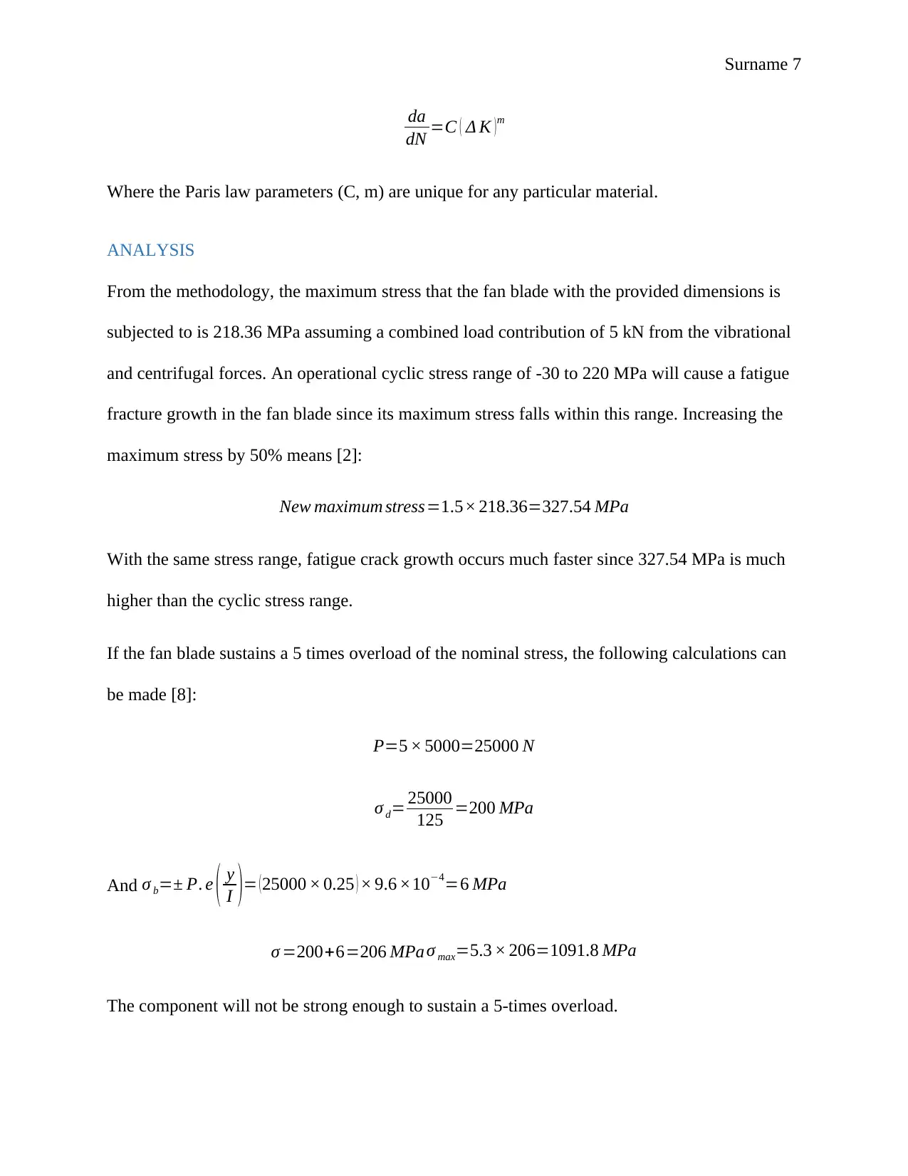
The fan blades fatigue life predictions can be determined by the HCF data for Ti-6Al-4V I shown
in the graphs of figure 1.4 [13]
Figure 1.4: Fan fatigue life predictions from maximum stress.
For a stress range of 0-220 MPa of the base loading cycle, the maximum stress used from fatigue
life prediction is 220MPa. At 220 MPa, the fatigue life of Ti6-4 is 22000 hours from figure 1.4.
Inspections are scheduled at 70% of the predicted life is given by:
tinspect=0.7 ×22,000=154 00 hours
Introduction of a minor vibrational cycle of 200-240 MPa to superimpose the major stress cycle
of the fan blade leads to more frequent scheduled inspections due to the reduction of component
predicted life. The maximum stress for this combination is 240 MPa and the corresponding
predicted lie of 16000 hours from figure 1.4. The new inspection period is:
Surname 9
tinspect=0.7 ×16 , 000=11200 hours
Small scale yielding (SSY) conditions are met for all stress conditions and the Ti6-4 material
will eventually yield under the calculated stress cases [4]
DISCUSSION
As from the analysis above, the small-scale yielding (SSY) conditions are met since the stress
ranges needed for crack growth initiation is quite low. This can be attributed to the large initial
defect size of the fan blade crack as well as the assumption that the component can be modelled
as a rectangular center-cracked plate [16].
Material choices for fan blade are based on their ductility, yield strength, HCF strength and
damage tolerance. The trade-off amongst the aerodynamic efficiency, weight and cost present a
main challenge of fan blade material selection. Titanium-based alloys have been employed in the
fan blade design and manufacturing for large turbofan engine equipment due to their good
performance such as unique physical, corrosion and mechanical properties as seen in this paper.
Its availability, ease of fabrication and intrinsic metallurgical properties gives it an edge over
other materials. However, titanium is very expensive compared to the potential materials that
can be used for the fan blades [15].
Metal matrix composite (MMC) materials are finding application for fan blades due to the high
strength-to-density and stiffness-to-density ratios that they offer. Fan blades made from
composite materials are lighter and contribute to the overall weight savings of the engine. Lower
stresses and centrifugal loads can be achieved and is beneficial in increasing the fatigue strength
of the fan blade. However, MMC materials are too expensive for wide application of fan blade
manufacturing [15].
⊘ This is a preview!⊘
Do you want full access?
Subscribe today to unlock all pages.
Trusted by 1+ million students worldwide
Surname 10
Hybrid metallic materials have improved structural strengths and are becoming popular in fan
blade fabrication. They provide both weight and structural benefits by combining the structural
stiffness of titanium and the lightness of the composite design materials. Use of hybrid-metallic
materials reduces the costs of construction and increases engine’s tolerance to bird impact
strikes. However, these materials are not durable and a life assessment is required more
frequently [13].
CONCLUSIONS
In summary, the fracture mechanics analysis of the aero-engine’s fan blade was performed with
consideration of thermal and mechanical forces. The nonlinearities that exist in the fan blade
structure forced an assumption of a center-cracked plate to be made. Using Paris-Erdogan law,
the values of stress integrity factor was obtained from the crack growth curves as a show under
the methodology. Information obtained from the crack growth was used to determine the period
between scheduled technical engine inspections. The damage tolerance analysis is useful in
detecting the crack growth before it reaches a critical size to avoid catastrophic rupture. It is
recommended that damage tolerance analysis be frequently done, not only to the fan blades but
also other components of the aircraft to ensure safety of the flight.
Paraphrase This Document
Need a fresh take? Get an instant paraphrase of this document with our AI Paraphraser
Surname 11
Part B: Life Assessment of Steam Power Plant Header Piping System
INTRODUCTION
In modern power plants, low-alloyed ferritic steels are in extensive use for high temperature
applications. The steels are used for high-temperature components such as steam pipes and
headers in power generation plants due to their good resistance to hydrogen embrittlement and
oxidation together with good elevated temperature creep strength. Considering that the typical
stress and operating temperature in the power plant are about 50 MPa and 5500C respectively, the
main life-limiting factor of the steam pipes and headers is creep [17].
Reduction in the mechanical properties of the materials necessitates plant integrity assessment in
order to reach a definite design life of the components. Oftentimes, component replacement may
be necessary even before the design life. The remaining life assessment of the high-temperature
components is thus needed from both safety and economic perspectives. Two approaches will be
explored in creep life prediction; post-service examination approach and operational parameter
approach [18].
Surname 12
LITERATURE REVIEW
Use of low-alloyed steels in steam plant piping system
Low-alloyed steels have been used for high-temperature applications since the development of
the first low Chromium (Cr) and Molybdenum (Mo) steels just after the First World War. Later,
Vanadium (V) was appreciated due to its beneficial properties on creep rupture. Power plant
pipes and tubes of the 0.5Mo-0.2V (wt %) alloy steels were the first to be installed. According to
material specifications of the ASME B31.1 standards, CMV low-alloyed steel pipe materials are
manufactured with the major alloying elements as Cr (0.5 wt %), Mo (0.5 wt %) and V(0.25 wt
%) [19]. CMV materials have uniform fine dispersion of precipitates that are distributed over the
material surface thus improving the creep strength.
Creep life prediction
Creep is the distortion of a material properties due to stresses below the material’s yield stress
when the material is exposed to high operating temperatures. The available creep life prediction
approaches for power plant components can be classified broadly into post-service examination
approach and operational approach [20].
The operational parameter approach is used to evaluate the stress history and the service
temperature of the given component. The historical data is combined with the lowest standard
value from the material data to assess the remaining life. The creep life prediction is done by the
life fraction rule as indicated in figure 2.1 [17].
Life fraction rule:
∑ t (σ ,T )
tR ( σ ,T )=1
⊘ This is a preview!⊘
Do you want full access?
Subscribe today to unlock all pages.
Trusted by 1+ million students worldwide
1 out of 21
Related Documents


Your All-in-One AI-Powered Toolkit for Academic Success.
+13062052269
info@desklib.com
Available 24*7 on WhatsApp / Email
![[object Object]](/_next/static/media/star-bottom.7253800d.svg)
Unlock your academic potential
Copyright © 2020–2026 A2Z Services. All Rights Reserved. Developed and managed by ZUCOL.