Finite Element Analysis of Bicycle Crank for Structural Assessment

Verified

Added on  2023/06/13

|10
|1288
|301
Report
AI Summary
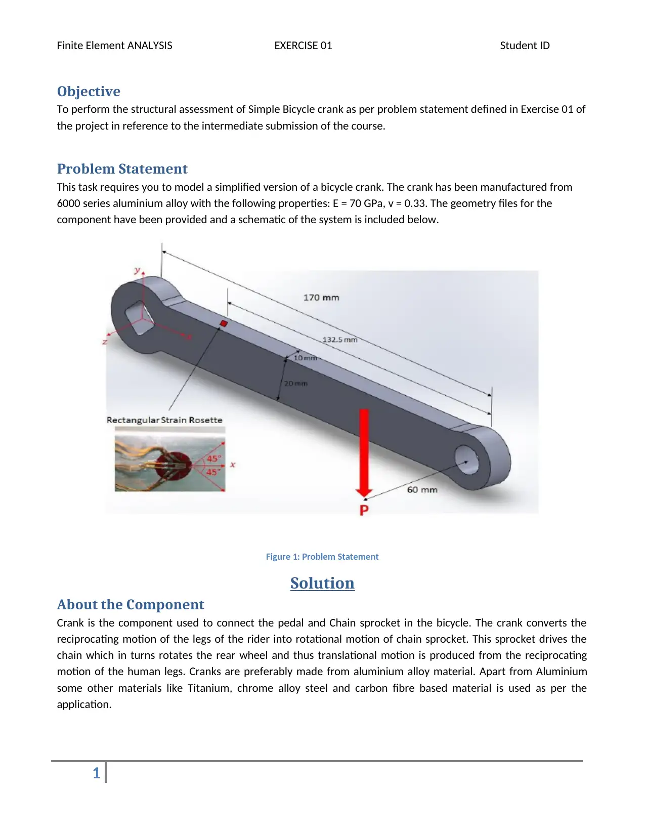
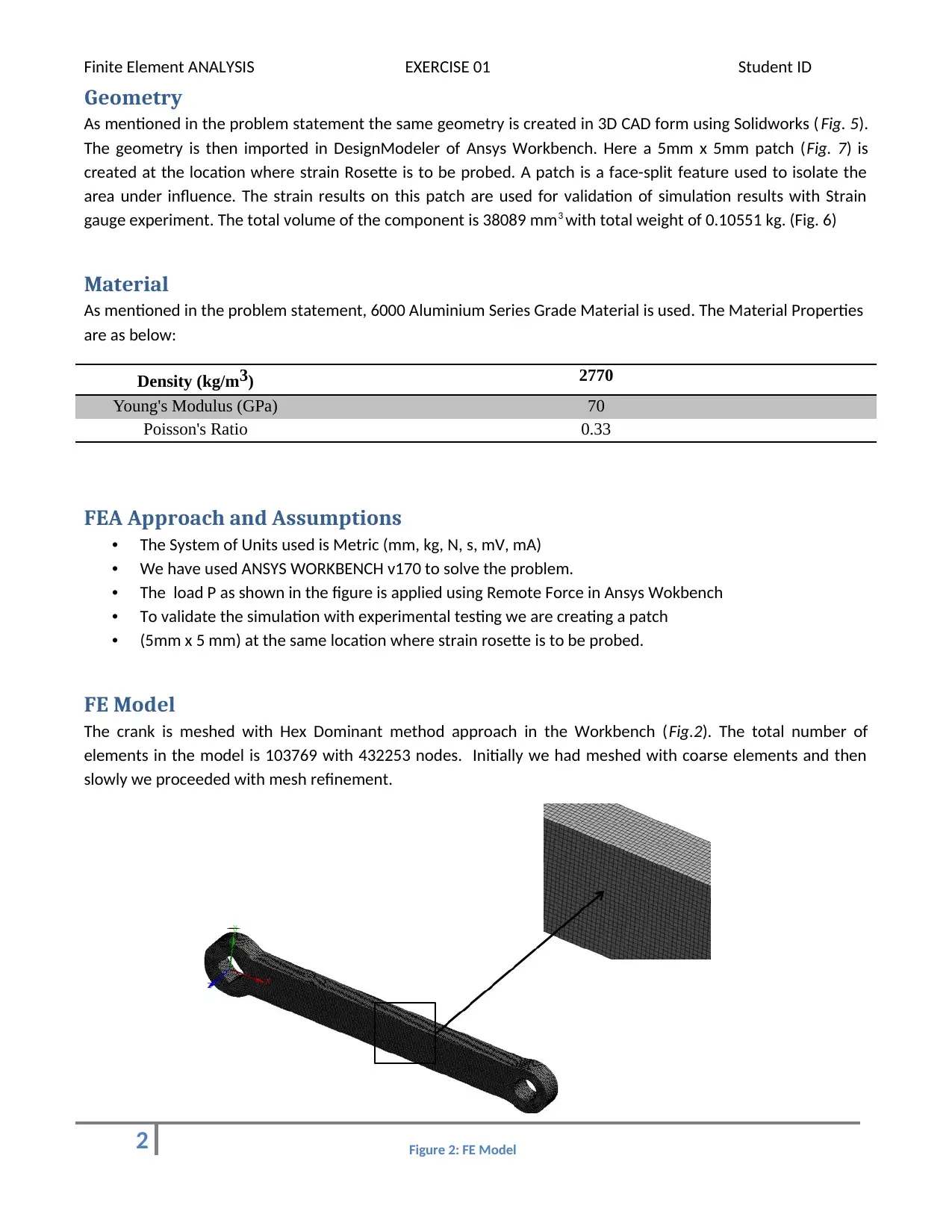
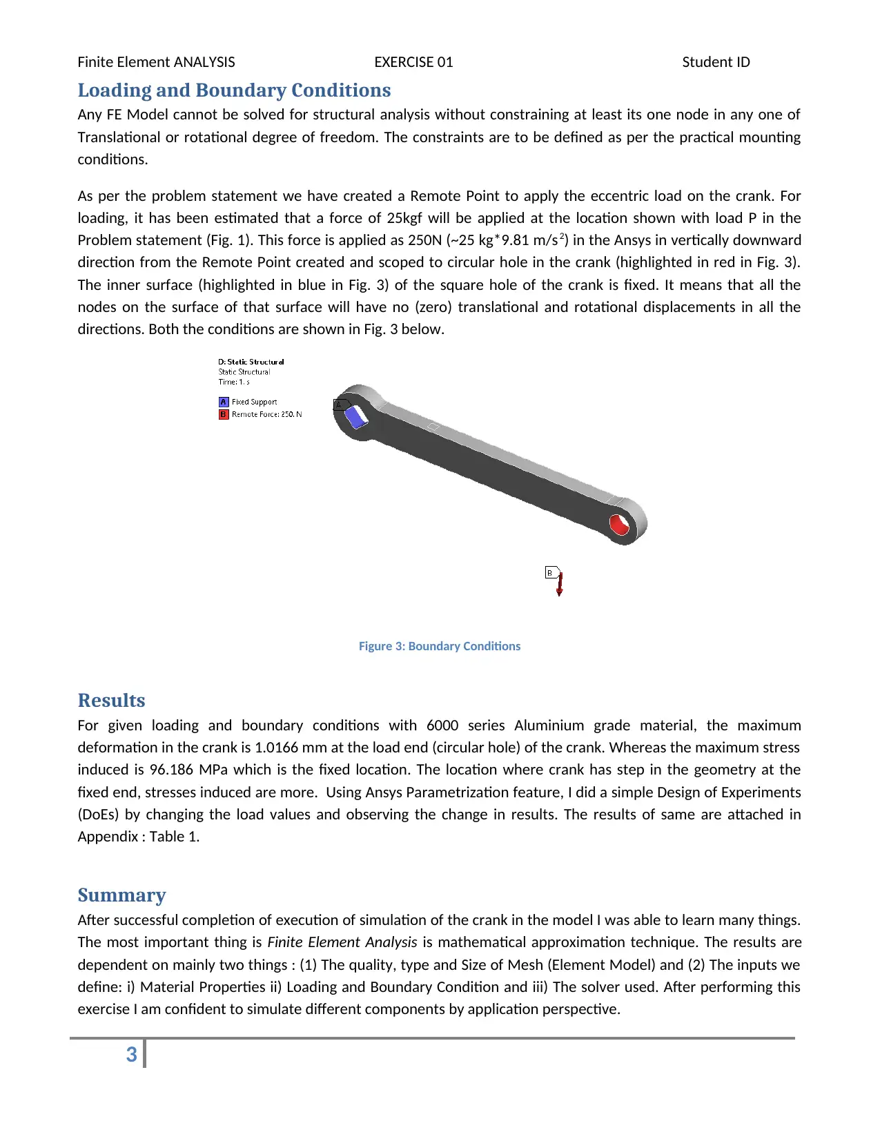
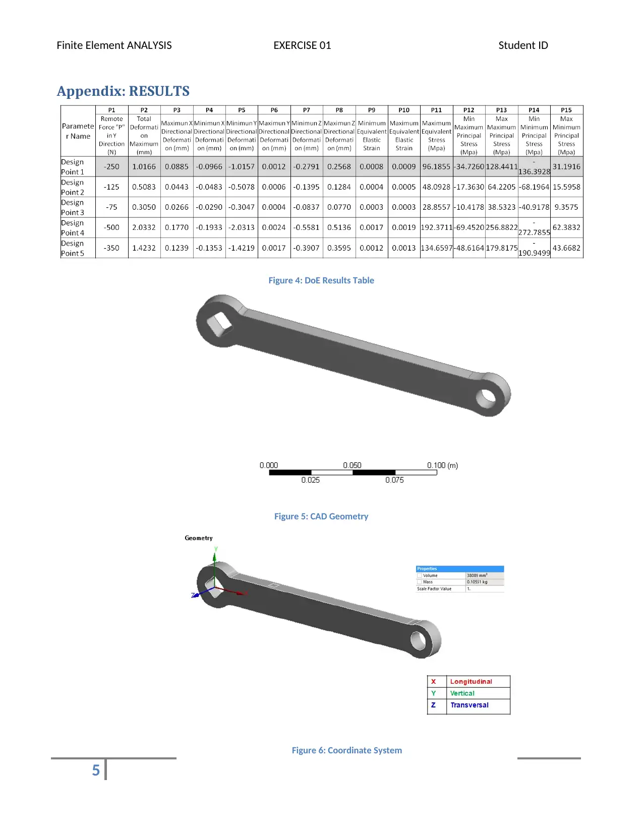
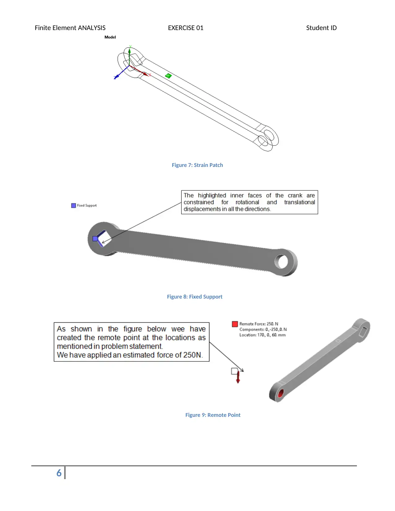
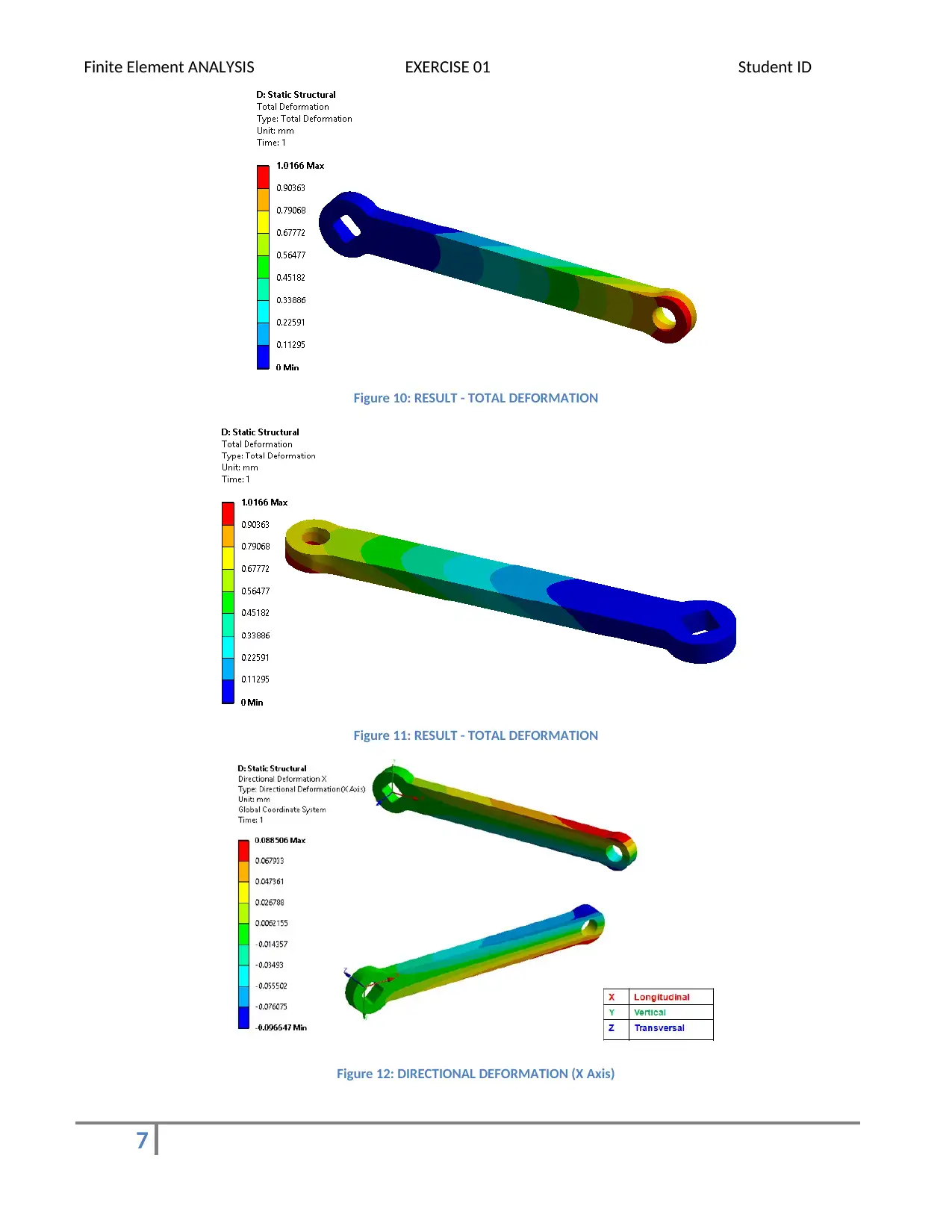
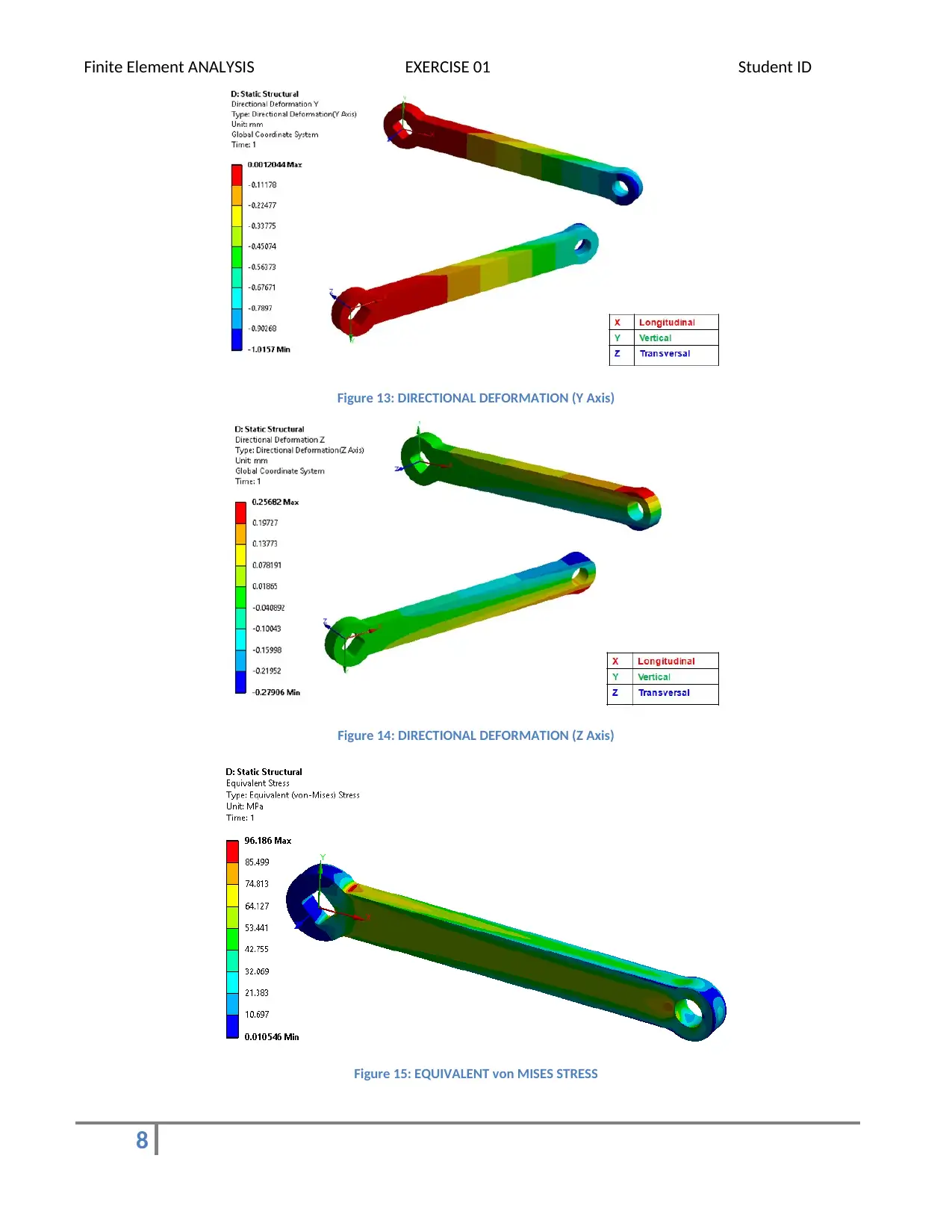
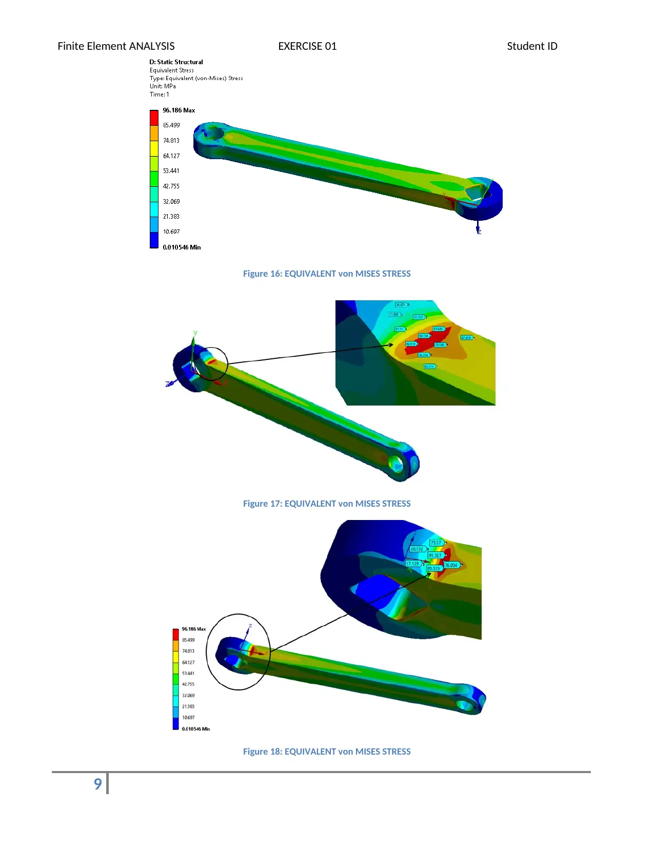
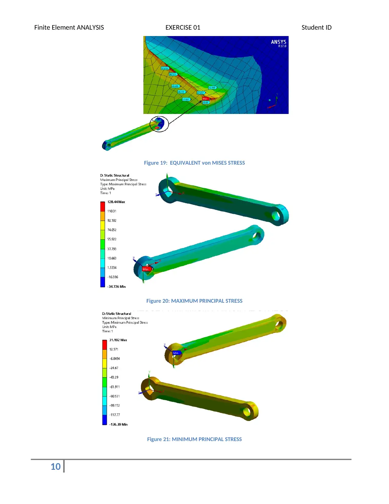
This report presents a finite element analysis (FEA) of a simplified bicycle crank made from 6000 series aluminum alloy, focusing on its structural assessment. The crank model was created in Solidworks and imported into ANSYS Workbench for analysis, with a specific patch defined for strain validation. The analysis incorporates material properties, boundary conditions, and loading scenarios, simulating a 250N force applied to the crank. Results include deformation and stress distribution, with a maximum deformation of 1.0166 mm and a maximum stress of 96.186 MPa. The report also explores the impact of varying load values through a Design of Experiments (DoE). The study concludes that the crank's behavior is analogous to a cantilever beam, with stress concentrations at fixed ends and deformation at load points, emphasizing the importance of mesh quality, material properties, and boundary conditions in FEA accuracy. Desklib provides access to this and many other solved assignments.
tabler-icon-diamond-filled.svg

Contribute Materials

Your contribution can guide someone’s learning journey. Share your documents today.
Document Page
Finite Element ANALYSIS EXERCISE 01 Student ID
Objective
To perform the structural assessment of Simple Bicycle crank as per problem statement defined in Exercise 01 of
the project in reference to the intermediate submission of the course.
Problem Statement
This task requires you to model a simplified version of a bicycle crank. The crank has been manufactured from
6000 series aluminium alloy with the following properties: E = 70 GPa, v = 0.33. The geometry files for the
component have been provided and a schematic of the system is included below.
Figure 1: Problem Statement
Solution
About the Component
Crank is the component used to connect the pedal and Chain sprocket in the bicycle. The crank converts the
reciprocating motion of the legs of the rider into rotational motion of chain sprocket. This sprocket drives the
chain which in turns rotates the rear wheel and thus translational motion is produced from the reciprocating
motion of the human legs. Cranks are preferably made from aluminium alloy material. Apart from Aluminium
some other materials like Titanium, chrome alloy steel and carbon fibre based material is used as per the
application.
1
tabler-icon-diamond-filled.svg

Secure Best Marks with AI Grader

Need help grading? Try our AI Grader for instant feedback on your assignments.
Document Page
Finite Element ANALYSIS EXERCISE 01 Student ID
Geometry
As mentioned in the problem statement the same geometry is created in 3D CAD form using Solidworks ( Fig. 5).
The geometry is then imported in DesignModeler of Ansys Workbench. Here a 5mm x 5mm patch (Fig. 7) is
created at the location where strain Rosette is to be probed. A patch is a face-split feature used to isolate the
area under influence. The strain results on this patch are used for validation of simulation results with Strain
gauge experiment. The total volume of the component is 38089 mm3 with total weight of 0.10551 kg. (Fig. 6)
Material
As mentioned in the problem statement, 6000 Aluminium Series Grade Material is used. The Material Properties
are as below:
Density (kg/m3) 2770
Young's Modulus (GPa) 70
Poisson's Ratio 0.33
FEA Approach and Assumptions
The System of Units used is Metric (mm, kg, N, s, mV, mA)
We have used ANSYS WORKBENCH v170 to solve the problem.
The load P as shown in the figure is applied using Remote Force in Ansys Wokbench
To validate the simulation with experimental testing we are creating a patch
(5mm x 5 mm) at the same location where strain rosette is to be probed.
FE Model
The crank is meshed with Hex Dominant method approach in the Workbench (Fig.2). The total number of
elements in the model is 103769 with 432253 nodes. Initially we had meshed with coarse elements and then
slowly we proceeded with mesh refinement.
2 Figure 2: FE Model
Document Page
Finite Element ANALYSIS EXERCISE 01 Student ID
Loading and Boundary Conditions
Any FE Model cannot be solved for structural analysis without constraining at least its one node in any one of
Translational or rotational degree of freedom. The constraints are to be defined as per the practical mounting
conditions.
As per the problem statement we have created a Remote Point to apply the eccentric load on the crank. For
loading, it has been estimated that a force of 25kgf will be applied at the location shown with load P in the
Problem statement (Fig. 1). This force is applied as 250N (~25 kg*9.81 m/s2) in the Ansys in vertically downward
direction from the Remote Point created and scoped to circular hole in the crank (highlighted in red in Fig. 3).
The inner surface (highlighted in blue in Fig. 3) of the square hole of the crank is fixed. It means that all the
nodes on the surface of that surface will have no (zero) translational and rotational displacements in all the
directions. Both the conditions are shown in Fig. 3 below.
Figure 3: Boundary Conditions
Results
For given loading and boundary conditions with 6000 series Aluminium grade material, the maximum
deformation in the crank is 1.0166 mm at the load end (circular hole) of the crank. Whereas the maximum stress
induced is 96.186 MPa which is the fixed location. The location where crank has step in the geometry at the
fixed end, stresses induced are more. Using Ansys Parametrization feature, I did a simple Design of Experiments
(DoEs) by changing the load values and observing the change in results. The results of same are attached in
Appendix : Table 1.
Summary
After successful completion of execution of simulation of the crank in the model I was able to learn many things.
The most important thing is Finite Element Analysis is mathematical approximation technique. The results are
dependent on mainly two things : (1) The quality, type and Size of Mesh (Element Model) and (2) The inputs we
define: i) Material Properties ii) Loading and Boundary Condition and iii) The solver used. After performing this
exercise I am confident to simulate different components by application perspective.
3
Document Page
Finite Element ANALYSIS EXERCISE 01 Student ID
Conclusion
From this exercise we can conclude things mentioned as below:
As the load increases the stresses induced increases.
The stress induced near the fixed end maximum whereas the deformation is more at the other end.
The behaviour of crank is analogous to the behaviour of the cantilever beam loaded at free end.
To reduce the stresses the steps at the ends should smooth curve.
If possible undercut can also be made to reduce the stresses. Similar provisions are made in the rotating
shafts.
As the force acting on the crank is generated from human energy there is rarely any fluctuation in load
and also there are very less changes of any occasional or impact load.
The crank should not only survive the loads but also to the repeated loads. We can estimate the life of
the crank using Fatigue Analysis.
If the Factor of safety in the component is above 3 then we can go Topology Optimization to reduce the
material, weight and cost of the component.

4
tabler-icon-diamond-filled.svg

Secure Best Marks with AI Grader

Need help grading? Try our AI Grader for instant feedback on your assignments.
Document Page
Finite Element ANALYSIS EXERCISE 01 Student ID
Appendix: RESULTS
Figure 4: DoE Results Table
Figure 5: CAD Geometry
5
Figure 6: Coordinate System
Document Page
Finite Element ANALYSIS EXERCISE 01 Student ID
Figure 7: Strain Patch
6
Figure 8: Fixed Support
Figure 9: Remote Point
Document Page
Finite Element ANALYSIS EXERCISE 01 Student ID
Figure 10: RESULT - TOTAL DEFORMATION
Figure 11: RESULT - TOTAL DEFORMATION
Figure 12: DIRECTIONAL DEFORMATION (X Axis)
7
tabler-icon-diamond-filled.svg

Paraphrase This Document

Need a fresh take? Get an instant paraphrase of this document with our AI Paraphraser
Document Page
Finite Element ANALYSIS EXERCISE 01 Student ID
Figure 13: DIRECTIONAL DEFORMATION (Y Axis)
Figure 14: DIRECTIONAL DEFORMATION (Z Axis)
Figure 15: EQUIVALENT von MISES STRESS
8
Document Page
Finite Element ANALYSIS EXERCISE 01 Student ID
Figure 16: EQUIVALENT von MISES STRESS
Figure 17: EQUIVALENT von MISES STRESS
Figure 18: EQUIVALENT von MISES STRESS
9
Document Page
Finite Element ANALYSIS EXERCISE 01 Student ID
Figure 19: EQUIVALENT von MISES STRESS
Figure 20: MAXIMUM PRINCIPAL STRESS
Figure 21: MINIMUM PRINCIPAL STRESS
10
chevron_up_icon
1 out of 10
circle_padding
hide_on_mobile
zoom_out_icon
logo.png

Your All-in-One AI-Powered Toolkit for Academic Success.

Available 24*7 on WhatsApp / Email

[object Object]