FEA Stress Analysis of Crane Component - Ansys 15.0 - 1T Jib Crane
VerifiedAdded on 2023/04/11
|14
|1393
|404
Report
AI Summary
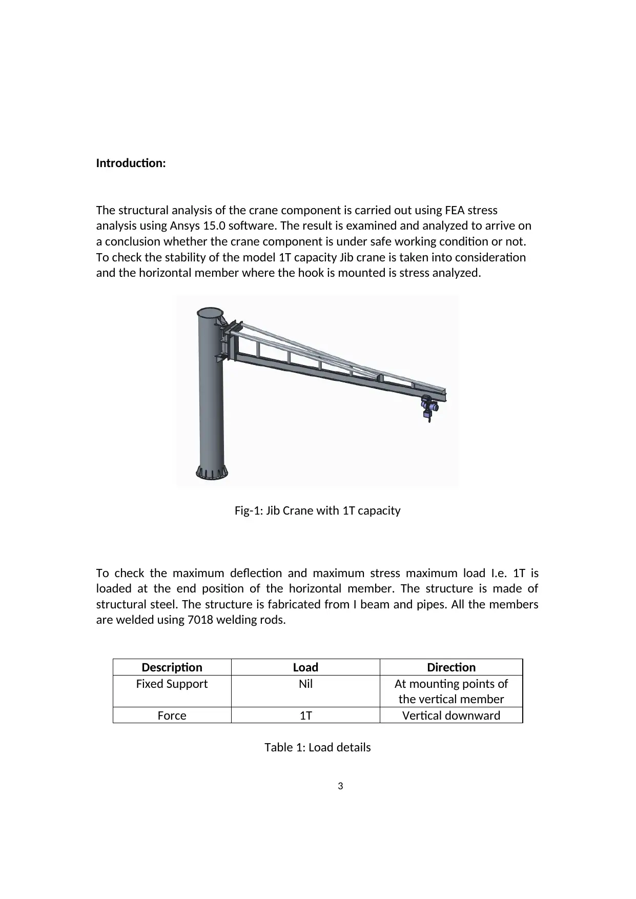
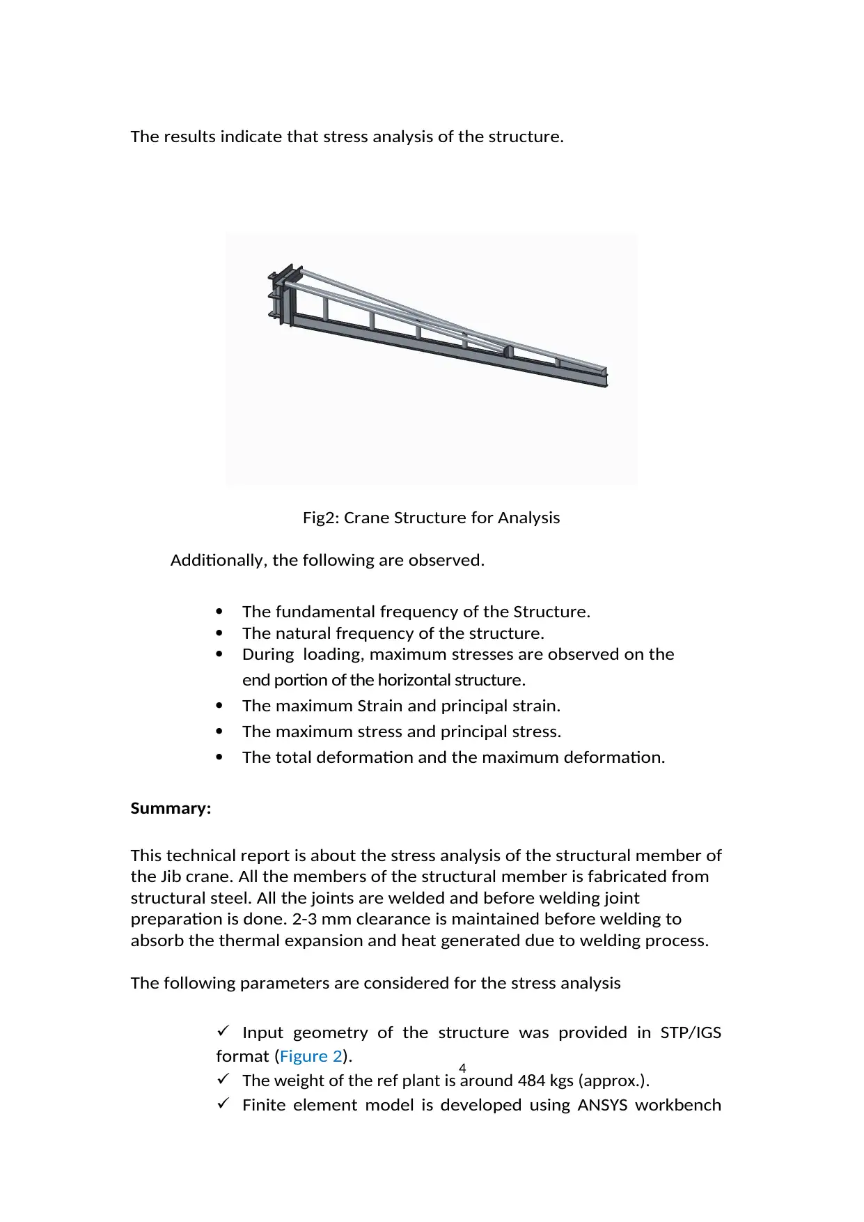
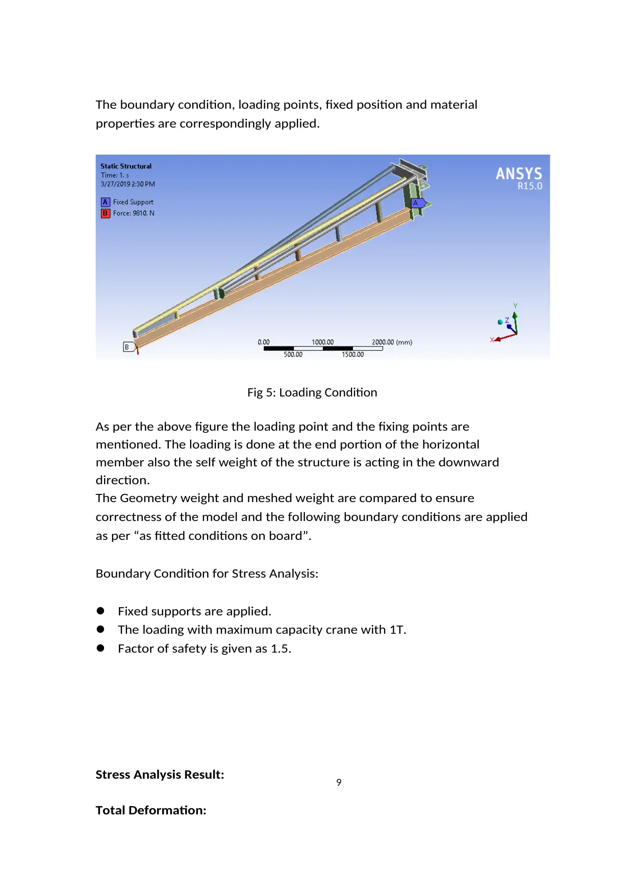
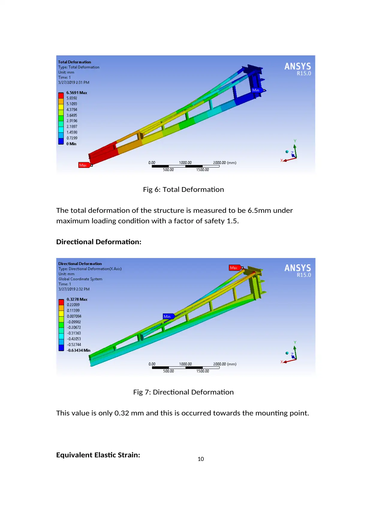
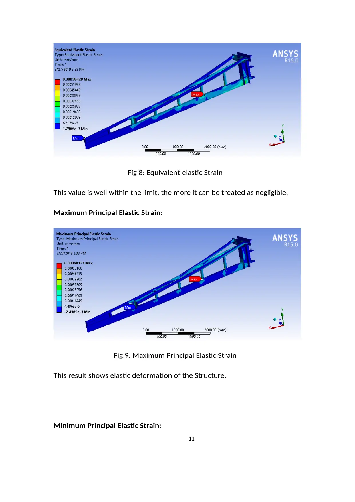
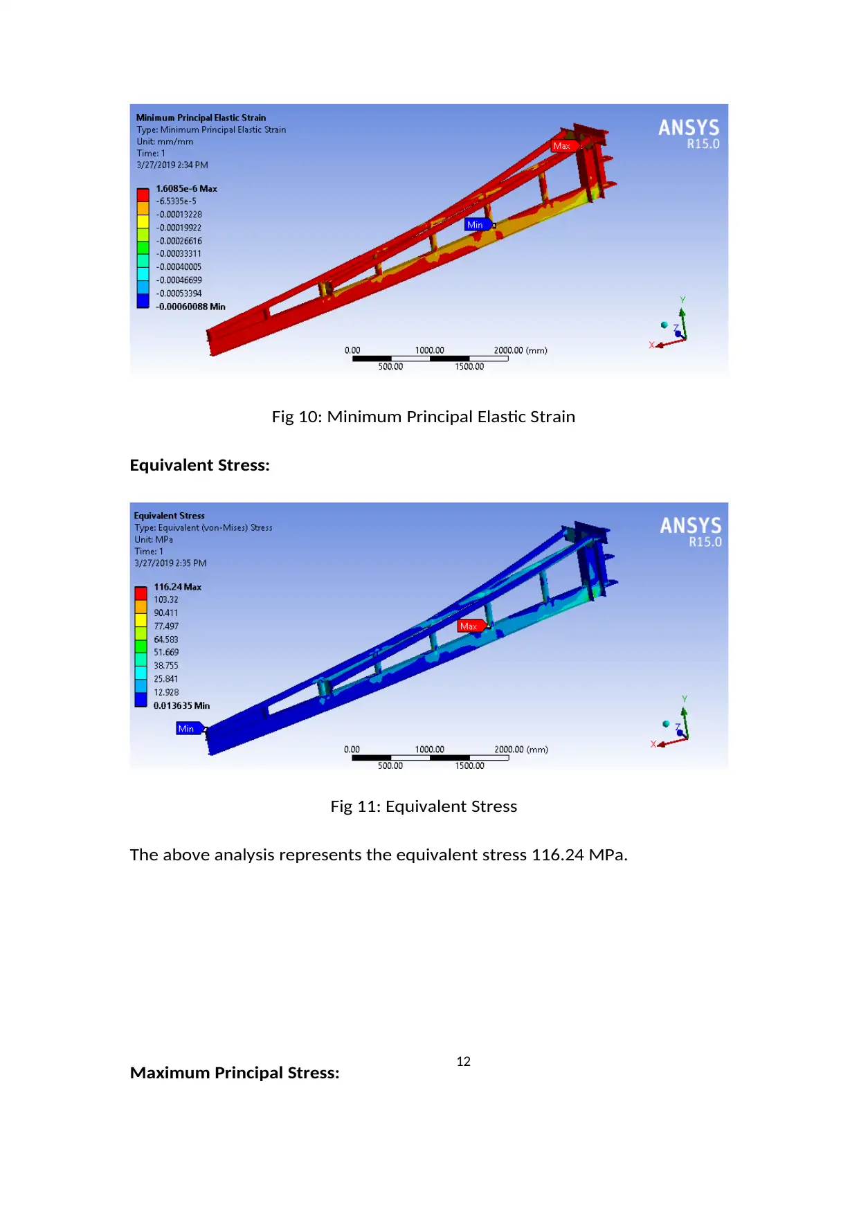
This report presents a stress analysis of a crane component, specifically the horizontal member of a 1T capacity Jib crane, using FEA in Ansys 15.0. The analysis investigates the structural integrity of the component under a 1T load, evaluating parameters such as deformation, stress (equivalent, maximum principal, and minimum principal), and strain (equivalent elastic, maximum principal elastic, and minimum principal elastic). The report details the development of the FEM model, boundary conditions, and material properties (structural steel). The results indicate that the structure is safe under the specified loading conditions, with the total deformation and equivalent stress well within acceptable limits. The conclusion suggests that the structure can be safely implemented and fabricated, with potential for further weight optimization by adjusting the structural members. Desklib provides a platform to access this and similar solved assignments.

1
PROJECT TITLE
STRESS ANALYSIS OF CRANE COMPONENT
REPORT NO :- DATE :
27/03/2019
PREPARED CHECKED APPROVED
DOCUMENT CHANGE NOTE :-
REV NO BY DESCRIPTION APPROVED DATE
PROJECT TITLE
STRESS ANALYSIS OF CRANE COMPONENT
REPORT NO :- DATE :
27/03/2019
PREPARED CHECKED APPROVED
DOCUMENT CHANGE NOTE :-
REV NO BY DESCRIPTION APPROVED DATE
Paraphrase This Document
Need a fresh take? Get an instant paraphrase of this document with our AI Paraphraser

2
Table of Content:
Introduction…………………………………………………………………………………………………Page 3
Summary……………………………………………………………………………………………………..Page 4
Problem Definition and Input……………………………………………………………………….Page 5
Material Properties………………………………………………………………………………………Page 5
Design Check Procedure……………………………………………………………………………….Page 6
Development of FEM Model…………………………………………………………………………Page 7
Boundary Condition……………………………………………………………………………………..Page 9
Stress Analysis Result………………………………………………………………………………….Page 10
Conclusion………………………………………………………………………………………………….Page 14

3
Introduction:
The structural analysis of the crane component is carried out using FEA stress
analysis using Ansys 15.0 software. The result is examined and analyzed to arrive on
a conclusion whether the crane component is under safe working condition or not.
To check the stability of the model 1T capacity Jib crane is taken into consideration
and the horizontal member where the hook is mounted is stress analyzed.
Fig-1: Jib Crane with 1T capacity
To check the maximum deflection and maximum stress maximum load I.e. 1T is
loaded at the end position of the horizontal member. The structure is made of
structural steel. The structure is fabricated from I beam and pipes. All the members
are welded using 7018 welding rods.
Description Load Direction
Fixed Support Nil At mounting points of
the vertical member
Force 1T Vertical downward
Table 1: Load details
⊘ This is a preview!⊘
Do you want full access?
Subscribe today to unlock all pages.

Trusted by 1+ million students worldwide

4
The results indicate that stress analysis of the structure.
Fig2: Crane Structure for Analysis
Additionally, the following are observed.
The fundamental frequency of the Structure.
The natural frequency of the structure.
During loading, maximum stresses are observed on the
end portion of the horizontal structure.
The maximum Strain and principal strain.
The maximum stress and principal stress.
The total deformation and the maximum deformation.
Summary:
This technical report is about the stress analysis of the structural member of
the Jib crane. All the members of the structural member is fabricated from
structural steel. All the joints are welded and before welding joint
preparation is done. 2-3 mm clearance is maintained before welding to
absorb the thermal expansion and heat generated due to welding process.
The following parameters are considered for the stress analysis
Input geometry of the structure was provided in STP/IGS
format (Figure 2).
The weight of the ref plant is around 484 kgs (approx.).
Finite element model is developed using ANSYS workbench
Paraphrase This Document
Need a fresh take? Get an instant paraphrase of this document with our AI Paraphraser

5
15.0.
Natural Frequencies are computed under appropriate
working conditions.
Loading on the horizontal member is given and fixed position
is given to the mounting position to the vertical member.
Stress analysis of all the member and the deflection of all the
member.
Problem Definition and Input:
The Objective of the analysis is to perform a computer aided simulation so as to
ascertain the mechanical integrity of the Structure when subjected to Load
Environment. The following parameter are investigated and illustrated in the
report.
Deformations at points of interest.
Von-mises / normal stress at various components.
The maximum strain
The principal strain
The maximum stress
The principal stress
Total deformation
Input Provided:
Data Provided
1 beam_structur
e_asm.stp
Table 2: Data Provided
Material Properties:
Data Provided
1 All the members are
structural steel
Table 3: Material Properties

6
Table 4: Material Properties for Ansys
Purpose:
Structure is required to operate in load environment qualifying Structure
standards. The analysis is to be carried out to ensure smooth performance and
satisfactory functioning in environment. Also check the maximum stress and
strain of the structure. As the member seems fabricated with proper truss and
rib we can expect the structure to withstand the load and vibration but we
need to check the values for computational and FEA analysis.
Design Check Procedure:
Selection ofstructural member as per user specifications.
Development of Geometric Model of the structural member from the
drawings and the 3D model
Deployment of FEM Model
Structural analysis
Identification of Eigen values
Post processing of response data,
Comparison of permissible stress levels vis-à-vis induced stress levels using
various theories of failure.
⊘ This is a preview!⊘
Do you want full access?
Subscribe today to unlock all pages.

Trusted by 1+ million students worldwide

7
Scope of Analysis:
The following types of analysis and load cases are defined and carried out
during FEM Simulation. The following are the analysis results carried out and
the results are analyse
The natural and generated frequency of the structure.
The load and fixing point in the model.
The Stress and and strain after loading.
The voinmass stress after loading.
Effect of different members after loading.
Development of FEM Model
Software Used:
The computation is performed using the finite element analysis (FEA) program
ANSYS®. The theoretical basis is documented in the ANSYS® THEORETICAL
MANUAL. ANSYS® is developed by ANSYS Inc., Canonsburg Pennsylvania. FEA
Model (FEM) of the structural member has been constructed and the finite
element model (meshing) has been generated with ANSYS Workbench
15.0 environment. It is then loaded into the workbench environment.
Inputs used:
The Bill of materials was provided and the following material properties were
used during the simulation. The weight as per the drawing is given in Tables
below. The bill of material and material properties of interest are elucidated in
Table 3 and Table 4 respectively. During the evaluation of the work, we use
the standards specified as a reference point. Weight data Sheet is given as
per the Table 5
Weight Data Sheet
Structural Member IS 2062 Weight 484 Kg
Table 5: weight data sheet
Paraphrase This Document
Need a fresh take? Get an instant paraphrase of this document with our AI Paraphraser

8
Idealization and Discretion
For the described objectives a computational simulation model is
generated. The discretion is done by means of Finite Element Method
(FEM). The finite element model is shown in the Figure3 . Elements Solid 186
& Solid 187 are used in generating the FE model. The element size is 100 mm.
The orthogonal quality of the mesh is 0.88 which is a very quality mesh. More is
the quality of the mesh better or accurate will be solution.
Fig 3: Mesh Details
Fig 4: Nodes and Element Details
Nodes and elements are within the desired limit. Nodes and elements
determines the number of matrix equation which ultimately solves to
determine the stress analysis report.
Boundary Condition:

9
The boundary condition, loading points, fixed position and material
properties are correspondingly applied.
Fig 5: Loading Condition
As per the above figure the loading point and the fixing points are
mentioned. The loading is done at the end portion of the horizontal
member also the self weight of the structure is acting in the downward
direction.
The Geometry weight and meshed weight are compared to ensure
correctness of the model and the following boundary conditions are applied
as per “as fitted conditions on board”.
Boundary Condition for Stress Analysis:
Fixed supports are applied.
The loading with maximum capacity crane with 1T.
Factor of safety is given as 1.5.
Stress Analysis Result:
Total Deformation:
⊘ This is a preview!⊘
Do you want full access?
Subscribe today to unlock all pages.

Trusted by 1+ million students worldwide

10
Fig 6: Total Deformation
The total deformation of the structure is measured to be 6.5mm under
maximum loading condition with a factor of safety 1.5.
Directional Deformation:
Fig 7: Directional Deformation
This value is only 0.32 mm and this is occurred towards the mounting point.
Equivalent Elastic Strain:
Paraphrase This Document
Need a fresh take? Get an instant paraphrase of this document with our AI Paraphraser

11
Fig 8: Equivalent elastic Strain
This value is well within the limit, the more it can be treated as negligible.
Maximum Principal Elastic Strain:
Fig 9: Maximum Principal Elastic Strain
This result shows elastic deformation of the Structure.
Minimum Principal Elastic Strain:
Fig 8: Equivalent elastic Strain
This value is well within the limit, the more it can be treated as negligible.
Maximum Principal Elastic Strain:
Fig 9: Maximum Principal Elastic Strain
This result shows elastic deformation of the Structure.
Minimum Principal Elastic Strain:

12
Fig 10: Minimum Principal Elastic Strain
Equivalent Stress:
Fig 11: Equivalent Stress
The above analysis represents the equivalent stress 116.24 MPa.
Maximum Principal Stress:
Fig 10: Minimum Principal Elastic Strain
Equivalent Stress:
Fig 11: Equivalent Stress
The above analysis represents the equivalent stress 116.24 MPa.
Maximum Principal Stress:
⊘ This is a preview!⊘
Do you want full access?
Subscribe today to unlock all pages.

Trusted by 1+ million students worldwide
1 out of 14

Your All-in-One AI-Powered Toolkit for Academic Success.
+13062052269
info@desklib.com
Available 24*7 on WhatsApp / Email
Unlock your academic potential
Copyright © 2020–2025 A2Z Services. All Rights Reserved. Developed and managed by ZUCOL.