Hydropower Plant Feasibility Study: Satara District, India
VerifiedAdded on 2023/06/07
|37
|8948
|126
Report
AI Summary
This research paper conducts a feasibility study of a hydropower plant in Satara District, India, aiming to identify limitations and potentials for improved performance, specifically focusing on the Koyna Hydropower project. The study proposes modifications and replacements of key components like wicket gates, wear plates, and seal rings to enhance efficiency by approximately 2% and increase the plant's capacity by 3% to 5%. These improvements involve adjusting dimensions and design profiles to achieve tighter clearances and optimized attack angles. The paper reviews renewable energy in India, the technical background of hydropower, and relevant case studies, including turbine improvements. It also details the advantages of the proposed turbine technology and concludes with recommendations for implementation. The study highlights the significance of hydropower in India's energy security and sustainable development and emphasizes the techno-economic viability of the projects depending on accessibility, hydrology, topology, and geology of the region.

dropo er PlantHy w 1
FEASIBILITY STUDY OF HYDROPOWER PLANT IN SATARA DISTRICT, INDIA
A Research Paper on Energy By
Student’s Name
Name of the Professor
Institutional Affiliation
City/State
Year/Month/Day
FEASIBILITY STUDY OF HYDROPOWER PLANT IN SATARA DISTRICT, INDIA
A Research Paper on Energy By
Student’s Name
Name of the Professor
Institutional Affiliation
City/State
Year/Month/Day
Paraphrase This Document
Need a fresh take? Get an instant paraphrase of this document with our AI Paraphraser
dropo er PlantHy w 2
ABSTRACT
This research paper presents a feasibility study of the hydropower plant in Satara District
in India. To ensure that the Koyna Hydropower project performs its stipulated functions
effectively, there is need of identification of the limitation and potentials of the power plants and
then proposing on the ways through which the performance of the project can be improved to
benefit the locals in Satara district. This feasibility study proposes the modification and
replacement of the three major components of hydro unit namely wicket gates, wear plates, and
seal rings which can improve the efficiency of Koyna Hydropower plant by approximately 2%
and the capacity of the plant can also be increased by 3 percent to 5 percent.
In order to attain such efficiency and performance, there is need of changing the
dimensions of seal rings and wear plates so as to have a tighter clearances, and the design profile
of wicket by increasing the attack angle by 2o, and also the edge gap trailing of the wicket gate
should be increased by 0.02inches. It is expected that the capacity and efficiency of the power
plant will be increased by 8000MW yearly per unit.
dropo er PlantHy w 3
Table of Contents
A T A TBS R C ....................................................................................................................................................2
T TIN RODUC ION...........................................................................................................................................4
AB CKGROUND.............................................................................................................................................5
ene a le ner ie in ndiaR w b E g s I ....................................................................................................................5
T ATLI ER URE REVIEW....................................................................................................................................7
er ie o dropo er Plant in atara i trictOv v w f Hy w S D s ....................................................................................7
Tec nical ac ro ndh B kg u ..............................................................................................................................8
nder ro nd Po er tationU g u w S ..................................................................................................................10
dropo er Plant iciencHy w Eff y.................................................................................................................11
A TC SE S UDY REVIEW.................................................................................................................................13
perational mpro ementO I v s...................................................................................................................14
lectricit Mar et pport nitieE y k O u s...........................................................................................................16
e Tec nolo ieN w h g s.................................................................................................................................17
T r ine mpro ementu b I v s......................................................................................................................18
A TC SE S UDY...............................................................................................................................................20
T THYDRO- URBINE UNI ...........................................................................................................................22
T M ATURBINE ODIFIC ION.......................................................................................................................24
eal inS R g............................................................................................................................................24
ear PlateW s.......................................................................................................................................25
ic et ateW k G .......................................................................................................................................26
A A TA T P P T TDV N GES OF HE RO OSED URBINE ECHNOLOGY...................................................................29
A MM ATCONCLUSION ND RECO END ION...................................................................................................31
APBIBLIOGR HY...........................................................................................................................................32
APPENDIXES...............................................................................................................................................33
⊘ This is a preview!⊘
Do you want full access?
Subscribe today to unlock all pages.
Trusted by 1+ million students worldwide
dropo er PlantHy w 4
LIST OF FIGURES
Figure 1: The technologies involved in the generation of hydropower system ……………... 10
Figure 2: Low and high prices of the hydropower plant ……………………………………... 18
Figure 3: Completed stator winding ………………………………………………………….. 19
Figure 4: Efficiency curves for different types of hydropower turbines …………...………… 20
Figure 5: Proposed wicket gate servo motor arm ………………..…………………………… 21
Figure 6: The primary hydro unit components which are majorly considered in the turbine
efficiency and performance improvement …………………………………………………… 23
Figure 7: Efficiency comparison between pre-overhaul and post-overhaul of turbine unit ….. 24
Figure 8: The proposed wear plated ready for bolting below and above wicket gate ………… 25
Figure 9: Seal rings of turbine runner …………………………………………………………. 26
Figure 10: Proposed refurbished wear plates of Nitronic 60 …………..……………………… 27
Figure 11: Stress analysis for turbine gates and flanges ……………………………………….. 28
Figure 12: Proposed optimized design of Wicket gates …….………………………………… 29
TABLE OF TABLES
Table 1: The type wise and sector wise breakup of the list of power stations in India ….….. 7
Table 2: The potential hydropower plants in India …………………………………..…..….. 8
Table 3: Variable parameters for Koyna Hydropower analysis ……….…………………… 13
Table 4: Comparison analysis of the energy parameters …………………………………… 14
Table 5: Expected values after overhauling the turbine unit of Koyna Hydropower project.. 30
Paraphrase This Document
Need a fresh take? Get an instant paraphrase of this document with our AI Paraphraser
dropo er PlantHy w 5
INTRODUCTION
India is one of the states with the largest generation of energy from the renewable energy
sources. However, apart from the hydropower, the other two abundant sources of energy are the
solar and wind which has remained untapped for the past 70 years majorly as a result of the
unavailability of relevant technologies and lack of political will. India is known by anyone that it
is the fourth largest emitter of carbon globally with its population of 1.3 billion with the major
contributor to this emotion being the power sector. However, in the recent decade, India has
made significant steps towards the development of the renewable energy.
The changes in the climatic conditions have been a great concern across the world hence
promoting the decision makers and government to establish a detailed blueprint for sustainable
and clean power for the entire population of India. Despite numerous efficiency improvements
needed are cost-effective, currently, there has not been a good quantification of the value streams
that the hydro plant can provide. Hence it is impossible to provide cost effective analysis when
making the upgrades. Some of the techniques that can be implemented in Koyna Hydropower
plant so as to improve its efficiency and performance include electricity market opportunities,
new technologies, and operational improvements. The modification and replacement of the three
major components of hydro unit namely wicket gates, wear plates, and seal rings can improve
the efficiency of Koyna Hydropower plant by approximately 2% and the capacity of the plant
can also be increased by 3 percent to 5 percent.
dropo er PlantHy w 6
BACKGROUND
Renewable Energies in India
The energy used in India can be categorized as either nonrenewable energy sources or
renewable energy sources. Renewable energy by definition is the energy sources that can
naturally be reproduced within the environment. The renewable sources of energy include
hydropower, wind energy, solar energy, and tidal energy. Solar energy is one of the most used
sources of renewable energy in India with an alarming growth rate of 50% annually. For the
conversion of solar energy into electrical energy, a device known as the photovoltaic cell is used
(Bansal, 2010). The ten machines in Gujarat province near Okha were some of the first wind
turbines installed in the country.
India has the 5th largest installed capacity of wind energy of 3595MW and the estimated
potential of wind energy being 45,000MW in the country. There are two categories of
hydropower plants in India, these include small and large plants. The small hydro plants have an
installed capacity less than 25MW and these projects are under the New and Renewable Energy
Ministry. The large hydro projects are the responsibility of the Ministry of Power (Bhatia, 2014).
The depletion of resources is an economic term which denotes the exhaustion of raw materials
within an area. The use of natural resources beyond their rate of replacement is considered to be
natural resources depletion [1].
Currently, the most significant source of energy used by the population in India is the
non-renewable energy sources. The value of these resources due to their demand despite the
decrease in their supply. Energy is the primary necessity for the development of the economy as
well as every sector in India. Therefore, it is necessary for the country to consider all the
emerging and new energy efficiency technologies and renewable energy and also implement the
laws of energy conservation (Boyle, 2012). With an exclusion of the hydropower energy, the
⊘ This is a preview!⊘
Do you want full access?
Subscribe today to unlock all pages.
Trusted by 1+ million students worldwide
dropo er PlantHy w 7
renewable energy in India accounts for a total installed capacity of 12,610MW of energy which
is equivalent to 9%.
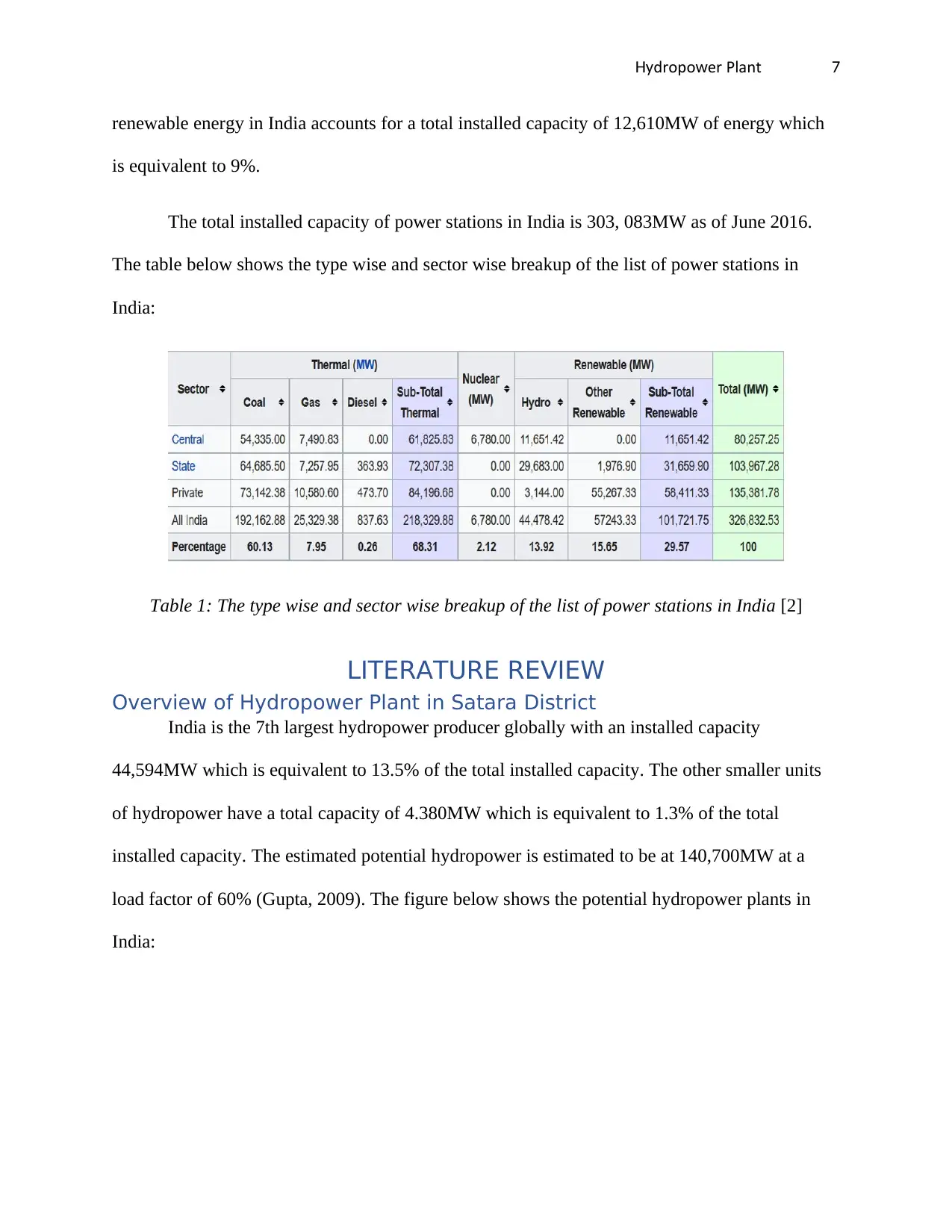
The total installed capacity of power stations in India is 303, 083MW as of June 2016.
The table below shows the type wise and sector wise breakup of the list of power stations in
India:
Table 1: The type wise and sector wise breakup of the list of power stations in India [2]
LITERATURE REVIEW
Overview of Hydropower Plant in Satara District
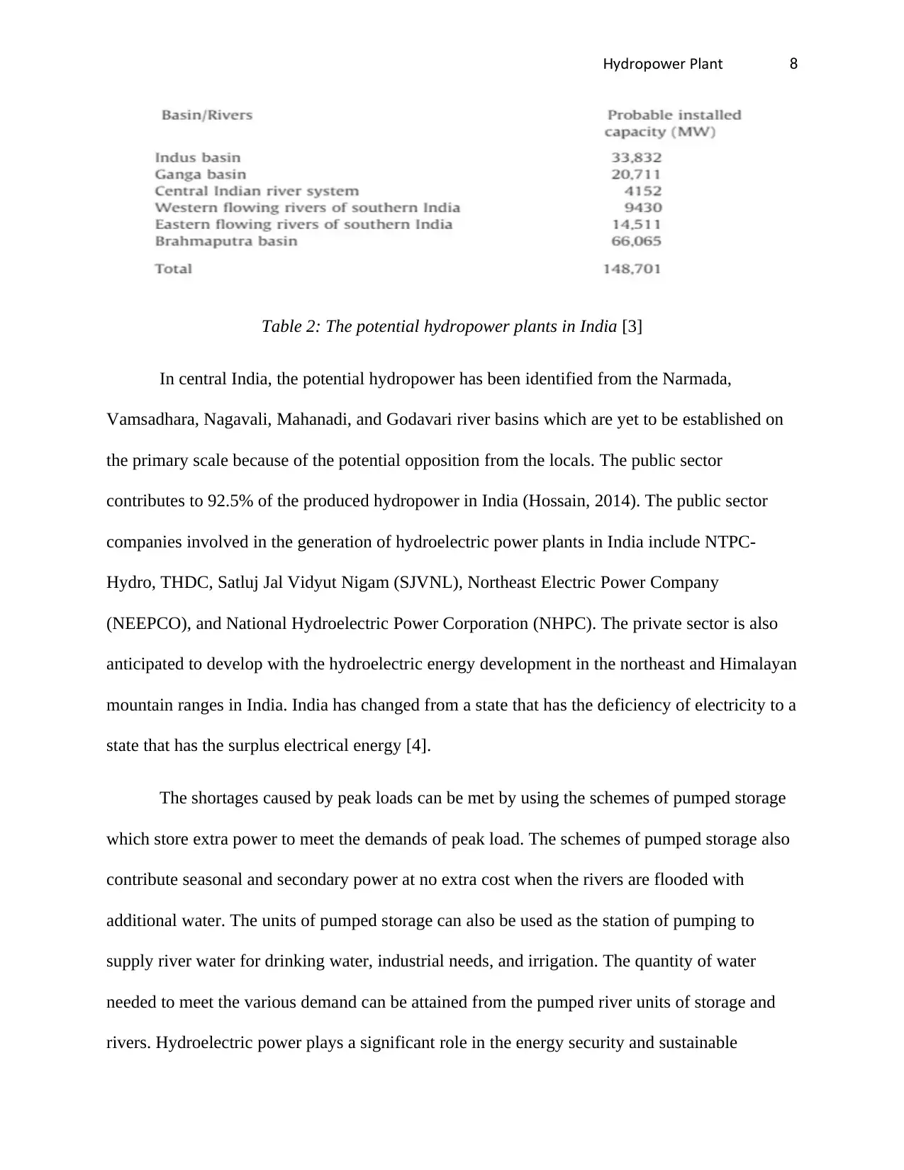
India is the 7th largest hydropower producer globally with an installed capacity
44,594MW which is equivalent to 13.5% of the total installed capacity. The other smaller units
of hydropower have a total capacity of 4.380MW which is equivalent to 1.3% of the total
installed capacity. The estimated potential hydropower is estimated to be at 140,700MW at a
load factor of 60% (Gupta, 2009). The figure below shows the potential hydropower plants in
India:
renewable energy in India accounts for a total installed capacity of 12,610MW of energy which
is equivalent to 9%.
The total installed capacity of power stations in India is 303, 083MW as of June 2016.
The table below shows the type wise and sector wise breakup of the list of power stations in
India:
Table 1: The type wise and sector wise breakup of the list of power stations in India [2]
LITERATURE REVIEW
Overview of Hydropower Plant in Satara District
India is the 7th largest hydropower producer globally with an installed capacity
44,594MW which is equivalent to 13.5% of the total installed capacity. The other smaller units
of hydropower have a total capacity of 4.380MW which is equivalent to 1.3% of the total
installed capacity. The estimated potential hydropower is estimated to be at 140,700MW at a
load factor of 60% (Gupta, 2009). The figure below shows the potential hydropower plants in
India:
Paraphrase This Document
Need a fresh take? Get an instant paraphrase of this document with our AI Paraphraser
dropo er PlantHy w 8
Table 2: The potential hydropower plants in India [3]
In central India, the potential hydropower has been identified from the Narmada,
Vamsadhara, Nagavali, Mahanadi, and Godavari river basins which are yet to be established on
the primary scale because of the potential opposition from the locals. The public sector
contributes to 92.5% of the produced hydropower in India (Hossain, 2014). The public sector
companies involved in the generation of hydroelectric power plants in India include NTPC-
Hydro, THDC, Satluj Jal Vidyut Nigam (SJVNL), Northeast Electric Power Company
(NEEPCO), and National Hydroelectric Power Corporation (NHPC). The private sector is also
anticipated to develop with the hydroelectric energy development in the northeast and Himalayan
mountain ranges in India. India has changed from a state that has the deficiency of electricity to a
state that has the surplus electrical energy [4].
The shortages caused by peak loads can be met by using the schemes of pumped storage
which store extra power to meet the demands of peak load. The schemes of pumped storage also
contribute seasonal and secondary power at no extra cost when the rivers are flooded with
additional water. The units of pumped storage can also be used as the station of pumping to
supply river water for drinking water, industrial needs, and irrigation. The quantity of water
needed to meet the various demand can be attained from the pumped river units of storage and
rivers. Hydroelectric power plays a significant role in the energy security and sustainable
dropo er PlantHy w 9
development in India since it attains the criteria of reliability, availability, and sustainability. The
techno-economic viability of the projects of hydroelectric energy depends on accessibility,
hydrology, topology, and geology of the region [5].
Technical Background
The techno-economic viability of the projects of hydroelectric energy depends on
accessibility, hydrology, topology, and geology of the region which in this case is the Satara
District. The technical background of the hydropower in Satara District evaluates the technical
performance and background of the Koyna Hydroelectric power plant which is a large plant with
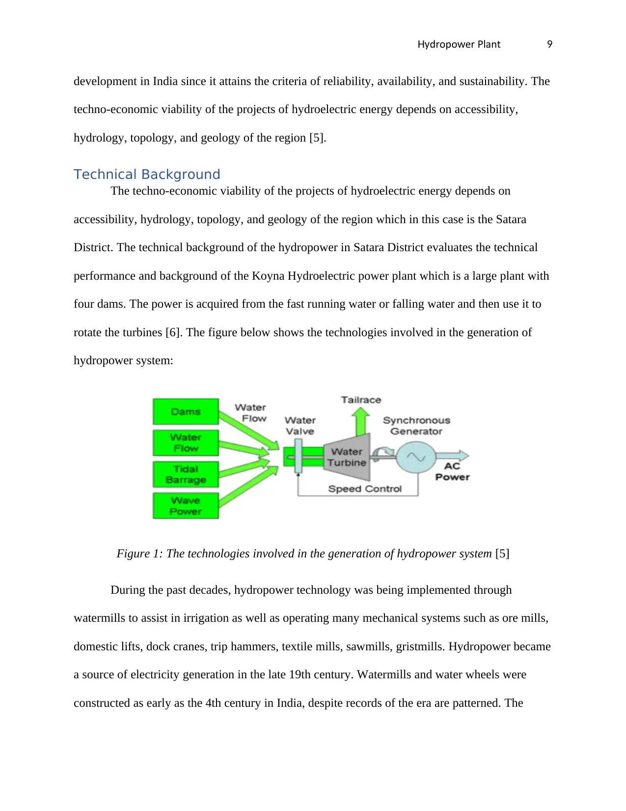
four dams. The power is acquired from the fast running water or falling water and then use it to
rotate the turbines [6]. The figure below shows the technologies involved in the generation of
hydropower system:
Figure 1: The technologies involved in the generation of hydropower system [5]
During the past decades, hydropower technology was being implemented through
watermills to assist in irrigation as well as operating many mechanical systems such as ore mills,
domestic lifts, dock cranes, trip hammers, textile mills, sawmills, gristmills. Hydropower became
a source of electricity generation in the late 19th century. Watermills and water wheels were
constructed as early as the 4th century in India, despite records of the era are patterned. The
development in India since it attains the criteria of reliability, availability, and sustainability. The
techno-economic viability of the projects of hydroelectric energy depends on accessibility,
hydrology, topology, and geology of the region [5].
Technical Background
The techno-economic viability of the projects of hydroelectric energy depends on
accessibility, hydrology, topology, and geology of the region which in this case is the Satara
District. The technical background of the hydropower in Satara District evaluates the technical
performance and background of the Koyna Hydroelectric power plant which is a large plant with
four dams. The power is acquired from the fast running water or falling water and then use it to
rotate the turbines [6]. The figure below shows the technologies involved in the generation of
hydropower system:
Figure 1: The technologies involved in the generation of hydropower system [5]
During the past decades, hydropower technology was being implemented through
watermills to assist in irrigation as well as operating many mechanical systems such as ore mills,
domestic lifts, dock cranes, trip hammers, textile mills, sawmills, gristmills. Hydropower became
a source of electricity generation in the late 19th century. Watermills and water wheels were
constructed as early as the 4th century in India, despite records of the era are patterned. The
⊘ This is a preview!⊘
Do you want full access?
Subscribe today to unlock all pages.
Trusted by 1+ million students worldwide
dropo er PlantHy w 10
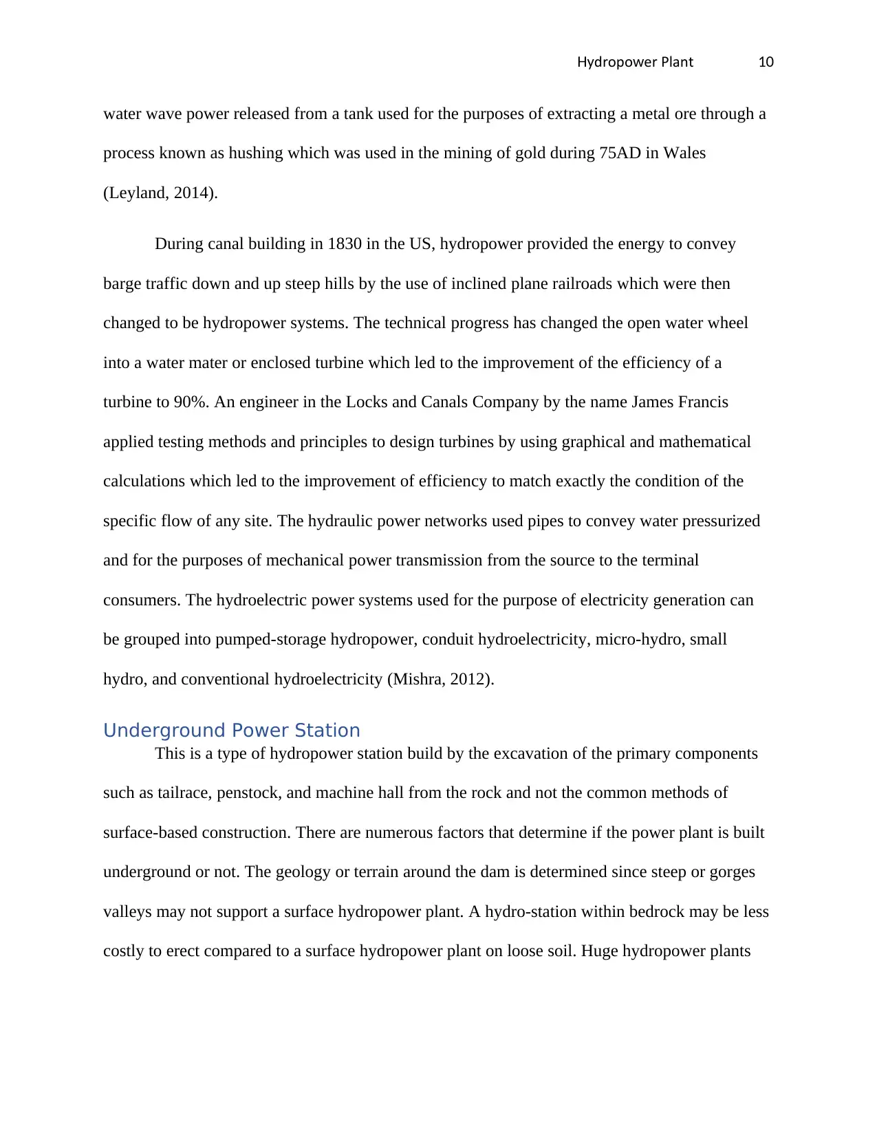
water wave power released from a tank used for the purposes of extracting a metal ore through a
process known as hushing which was used in the mining of gold during 75AD in Wales
(Leyland, 2014).
During canal building in 1830 in the US, hydropower provided the energy to convey
barge traffic down and up steep hills by the use of inclined plane railroads which were then
changed to be hydropower systems. The technical progress has changed the open water wheel
into a water mater or enclosed turbine which led to the improvement of the efficiency of a
turbine to 90%. An engineer in the Locks and Canals Company by the name James Francis
applied testing methods and principles to design turbines by using graphical and mathematical
calculations which led to the improvement of efficiency to match exactly the condition of the
specific flow of any site. The hydraulic power networks used pipes to convey water pressurized
and for the purposes of mechanical power transmission from the source to the terminal
consumers. The hydroelectric power systems used for the purpose of electricity generation can
be grouped into pumped-storage hydropower, conduit hydroelectricity, micro-hydro, small
hydro, and conventional hydroelectricity (Mishra, 2012).
Underground Power Station
This is a type of hydropower station build by the excavation of the primary components
such as tailrace, penstock, and machine hall from the rock and not the common methods of
surface-based construction. There are numerous factors that determine if the power plant is built
underground or not. The geology or terrain around the dam is determined since steep or gorges
valleys may not support a surface hydropower plant. A hydro-station within bedrock may be less
costly to erect compared to a surface hydropower plant on loose soil. Huge hydropower plants
Paraphrase This Document
Need a fresh take? Get an instant paraphrase of this document with our AI Paraphraser
dropo er PlantHy w 11
have been positioned underground frequently after the World War II so as to protect the plants
from airstrikes.
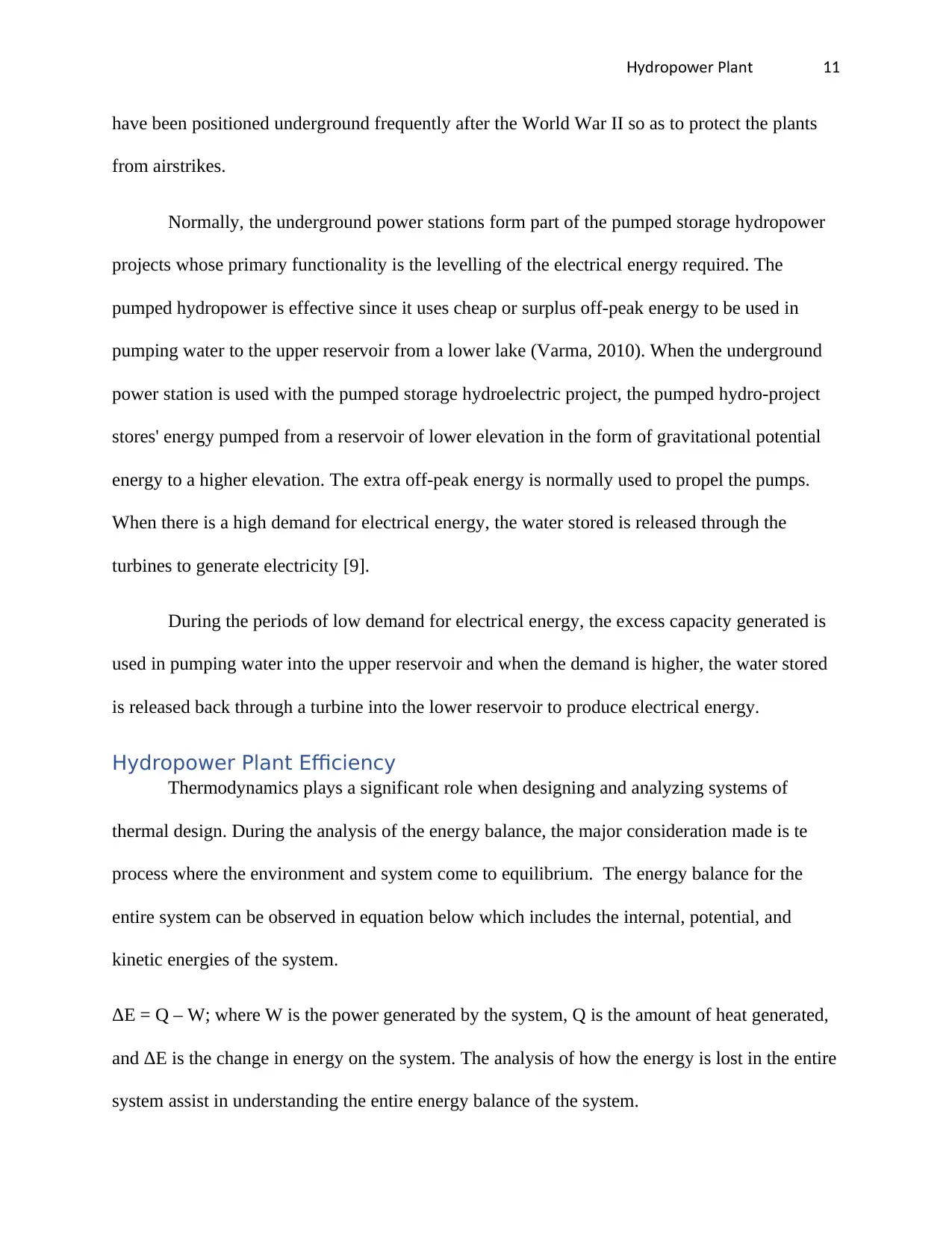
Normally, the underground power stations form part of the pumped storage hydropower
projects whose primary functionality is the levelling of the electrical energy required. The
pumped hydropower is effective since it uses cheap or surplus off-peak energy to be used in
pumping water to the upper reservoir from a lower lake (Varma, 2010). When the underground
power station is used with the pumped storage hydroelectric project, the pumped hydro-project
stores' energy pumped from a reservoir of lower elevation in the form of gravitational potential
energy to a higher elevation. The extra off-peak energy is normally used to propel the pumps.
When there is a high demand for electrical energy, the water stored is released through the
turbines to generate electricity [9].
During the periods of low demand for electrical energy, the excess capacity generated is
used in pumping water into the upper reservoir and when the demand is higher, the water stored
is released back through a turbine into the lower reservoir to produce electrical energy.
Hydropower Plant Efficiency
Thermodynamics plays a significant role when designing and analyzing systems of
thermal design. During the analysis of the energy balance, the major consideration made is te
process where the environment and system come to equilibrium. The energy balance for the
entire system can be observed in equation below which includes the internal, potential, and
kinetic energies of the system.
ΔE = Q – W; where W is the power generated by the system, Q is the amount of heat generated,
and ΔE is the change in energy on the system. The analysis of how the energy is lost in the entire
system assist in understanding the entire energy balance of the system.
have been positioned underground frequently after the World War II so as to protect the plants
from airstrikes.
Normally, the underground power stations form part of the pumped storage hydropower
projects whose primary functionality is the levelling of the electrical energy required. The
pumped hydropower is effective since it uses cheap or surplus off-peak energy to be used in
pumping water to the upper reservoir from a lower lake (Varma, 2010). When the underground
power station is used with the pumped storage hydroelectric project, the pumped hydro-project
stores' energy pumped from a reservoir of lower elevation in the form of gravitational potential
energy to a higher elevation. The extra off-peak energy is normally used to propel the pumps.
When there is a high demand for electrical energy, the water stored is released through the
turbines to generate electricity [9].
During the periods of low demand for electrical energy, the excess capacity generated is
used in pumping water into the upper reservoir and when the demand is higher, the water stored
is released back through a turbine into the lower reservoir to produce electrical energy.
Hydropower Plant Efficiency
Thermodynamics plays a significant role when designing and analyzing systems of
thermal design. During the analysis of the energy balance, the major consideration made is te
process where the environment and system come to equilibrium. The energy balance for the
entire system can be observed in equation below which includes the internal, potential, and
kinetic energies of the system.
ΔE = Q – W; where W is the power generated by the system, Q is the amount of heat generated,
and ΔE is the change in energy on the system. The analysis of how the energy is lost in the entire
system assist in understanding the entire energy balance of the system.
dropo er PlantHy w 12
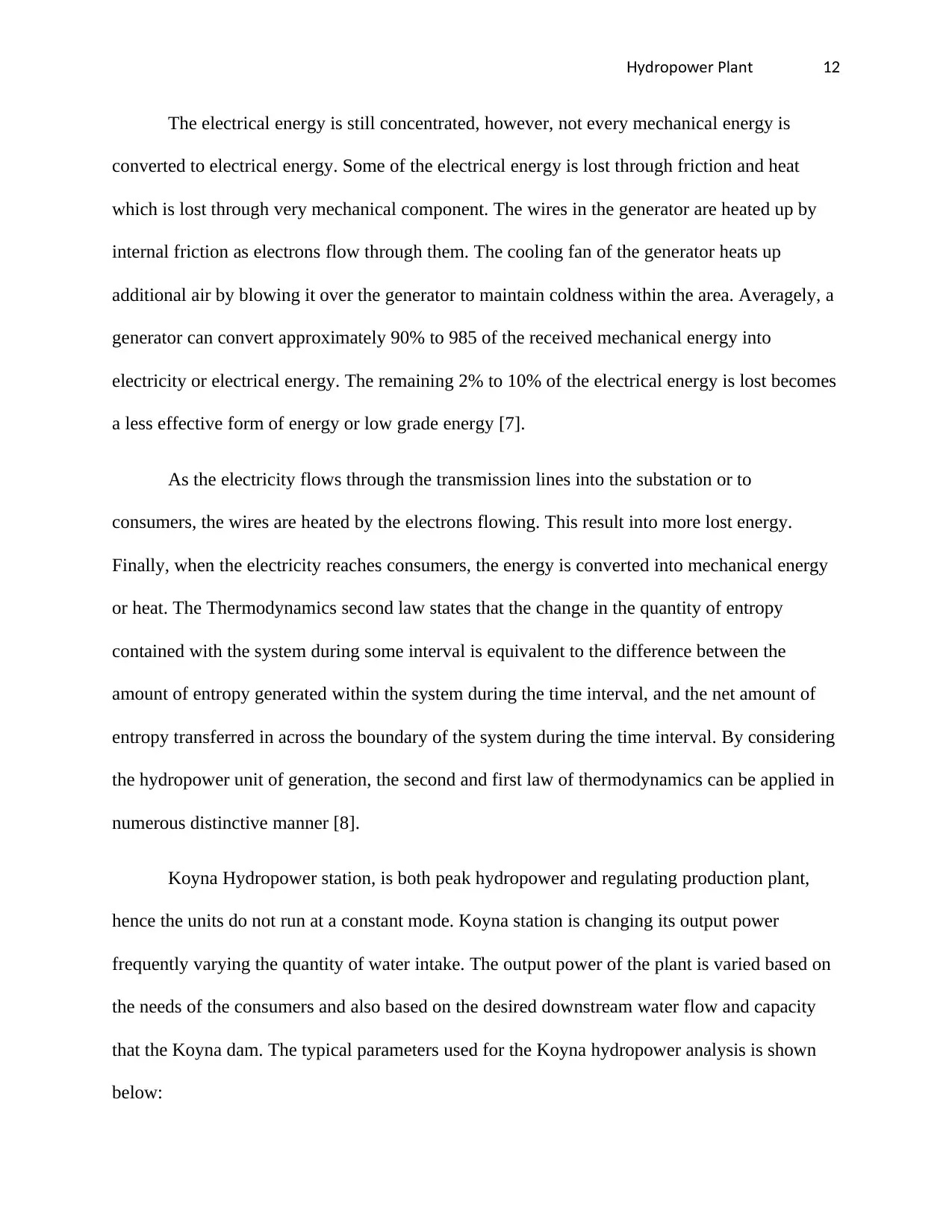
The electrical energy is still concentrated, however, not every mechanical energy is
converted to electrical energy. Some of the electrical energy is lost through friction and heat
which is lost through very mechanical component. The wires in the generator are heated up by
internal friction as electrons flow through them. The cooling fan of the generator heats up
additional air by blowing it over the generator to maintain coldness within the area. Averagely, a
generator can convert approximately 90% to 985 of the received mechanical energy into
electricity or electrical energy. The remaining 2% to 10% of the electrical energy is lost becomes
a less effective form of energy or low grade energy [7].
As the electricity flows through the transmission lines into the substation or to
consumers, the wires are heated by the electrons flowing. This result into more lost energy.
Finally, when the electricity reaches consumers, the energy is converted into mechanical energy
or heat. The Thermodynamics second law states that the change in the quantity of entropy
contained with the system during some interval is equivalent to the difference between the
amount of entropy generated within the system during the time interval, and the net amount of
entropy transferred in across the boundary of the system during the time interval. By considering
the hydropower unit of generation, the second and first law of thermodynamics can be applied in
numerous distinctive manner [8].
Koyna Hydropower station, is both peak hydropower and regulating production plant,
hence the units do not run at a constant mode. Koyna station is changing its output power
frequently varying the quantity of water intake. The output power of the plant is varied based on
the needs of the consumers and also based on the desired downstream water flow and capacity
that the Koyna dam. The typical parameters used for the Koyna hydropower analysis is shown
below:
⊘ This is a preview!⊘
Do you want full access?
Subscribe today to unlock all pages.
Trusted by 1+ million students worldwide
1 out of 37
Your All-in-One AI-Powered Toolkit for Academic Success.
+13062052269
info@desklib.com
Available 24*7 on WhatsApp / Email
![[object Object]](/_next/static/media/star-bottom.7253800d.svg)
Unlock your academic potential
Copyright © 2020–2026 A2Z Services. All Rights Reserved. Developed and managed by ZUCOL.