Finite Element Analysis of a Plate using ANSYS Workbench

Verified

Added on  2022/01/08

|14
|380
|23
Project
AI Summary
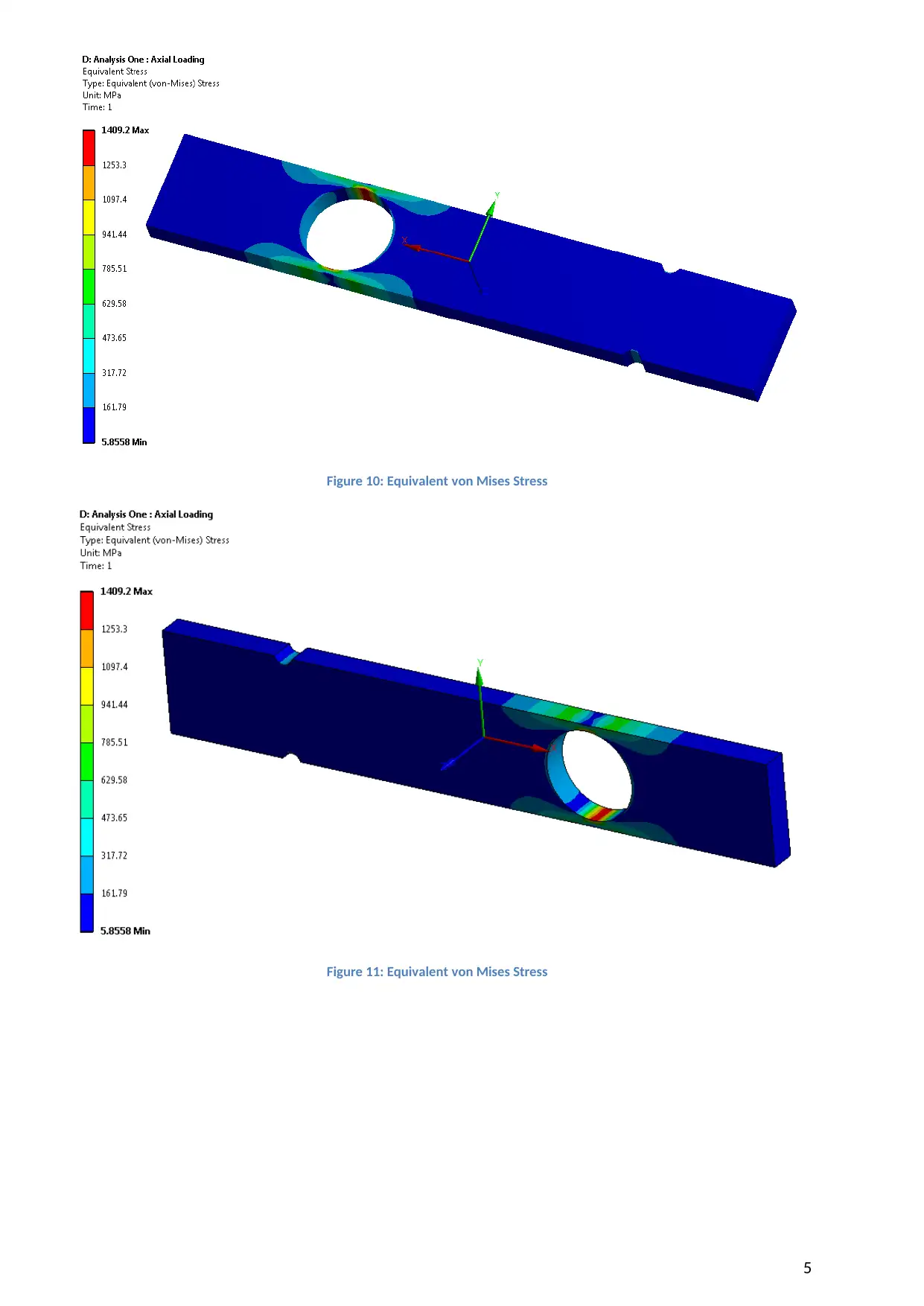
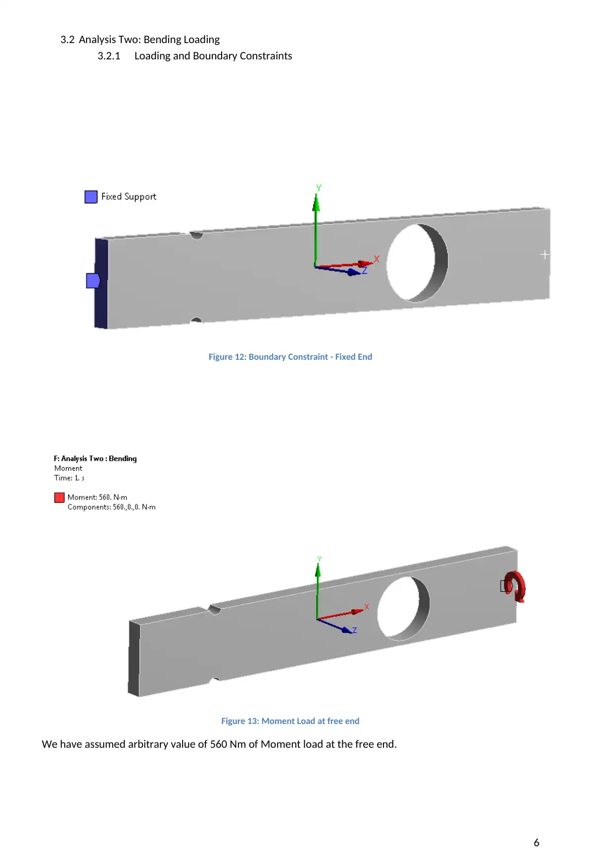
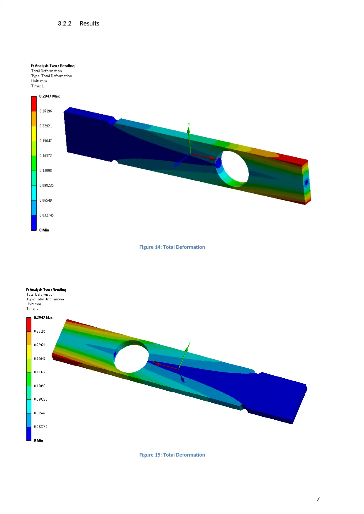
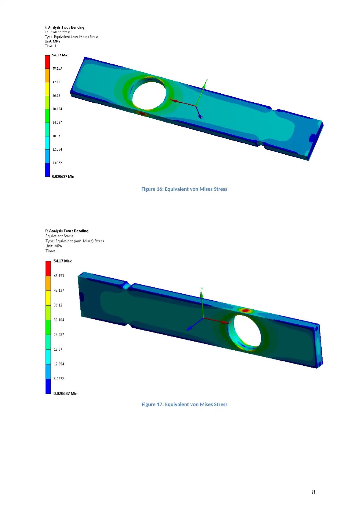
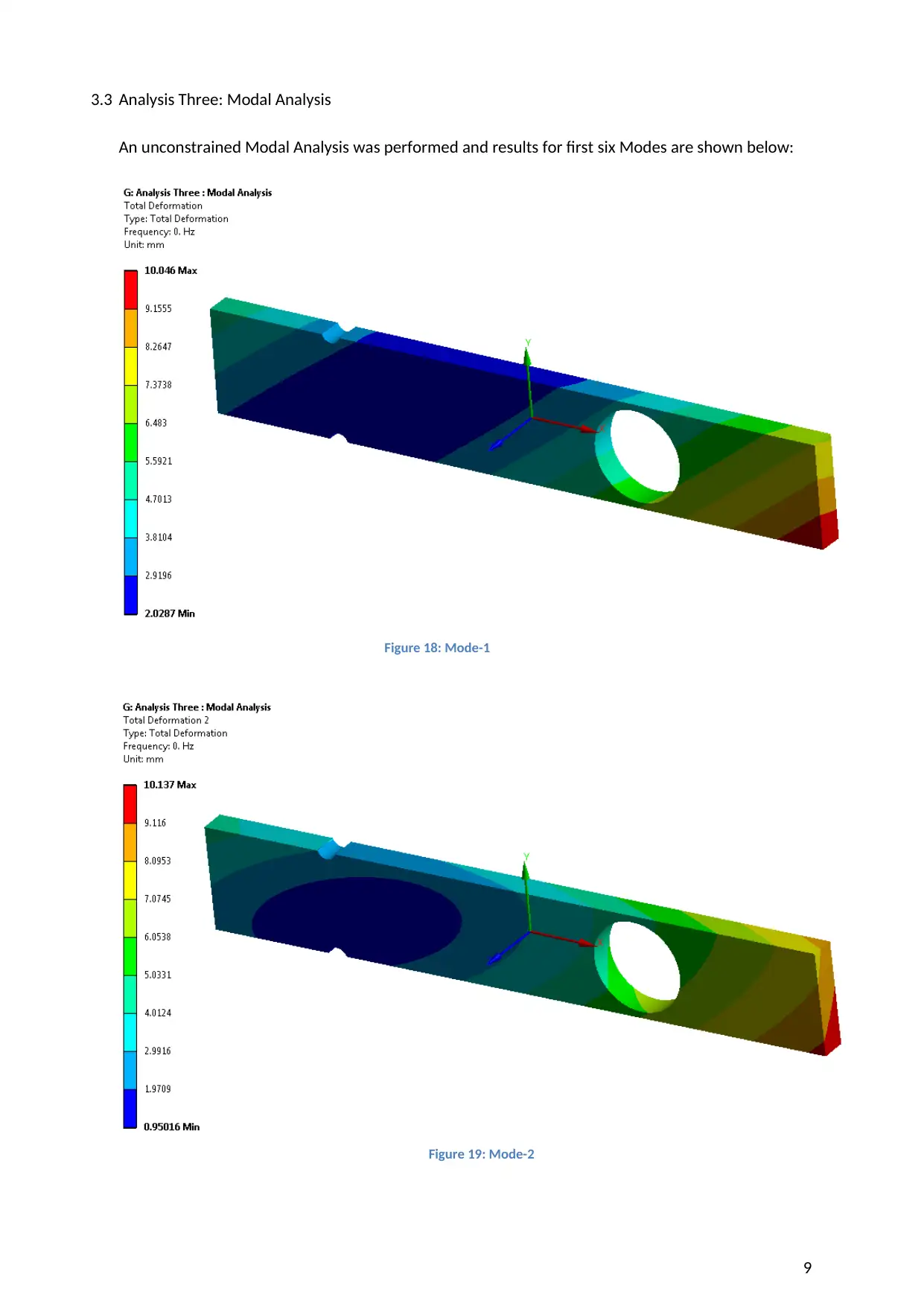
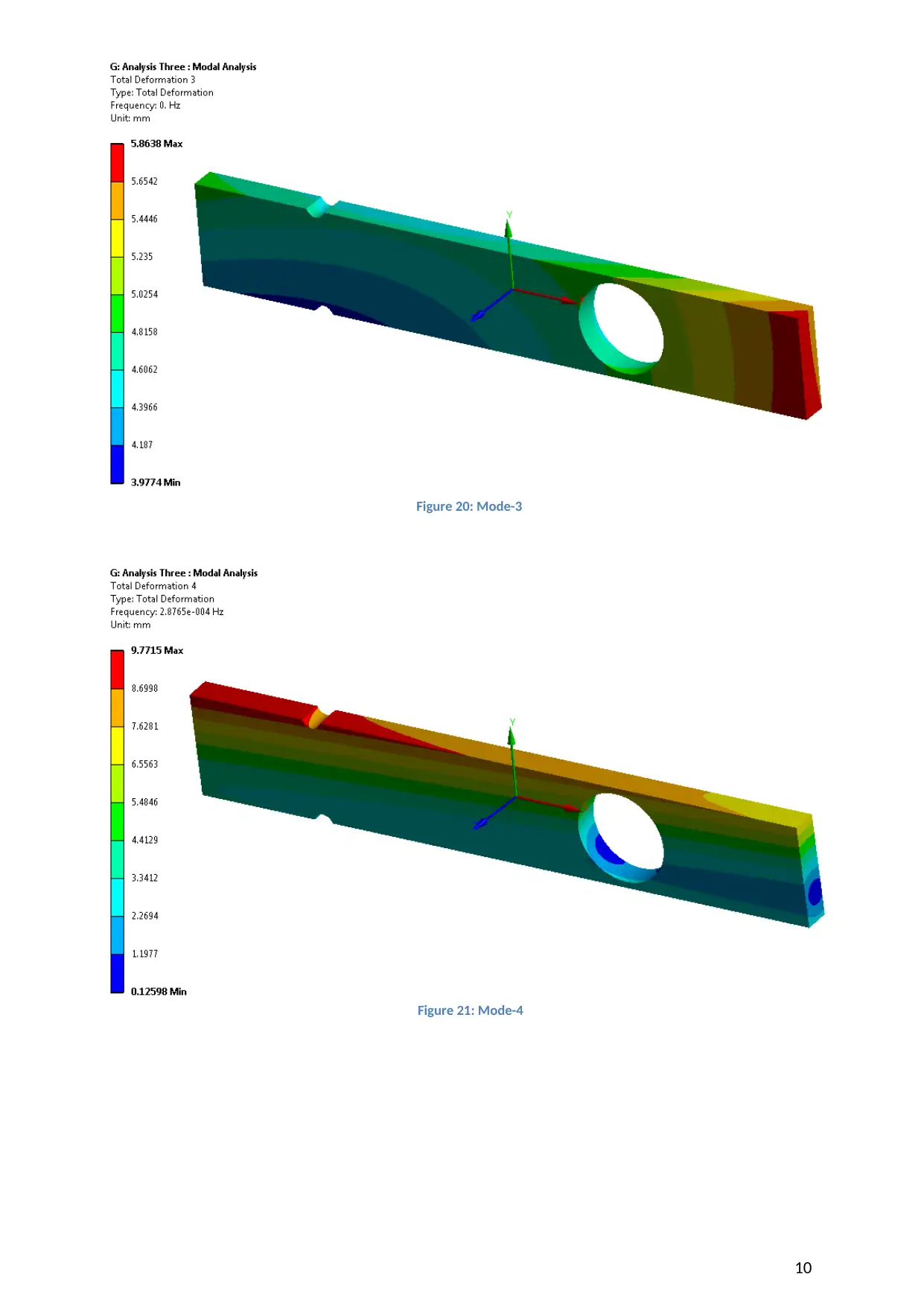
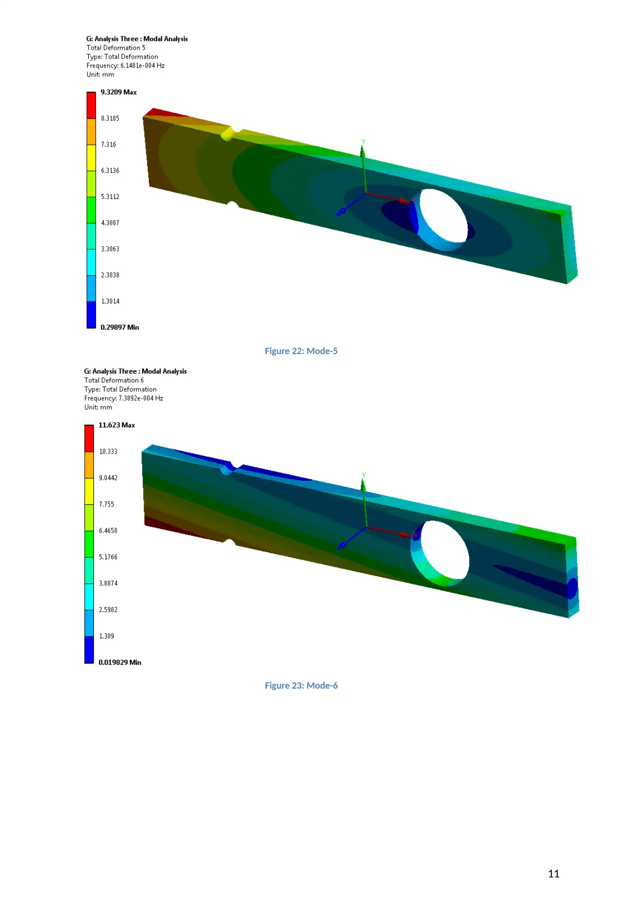
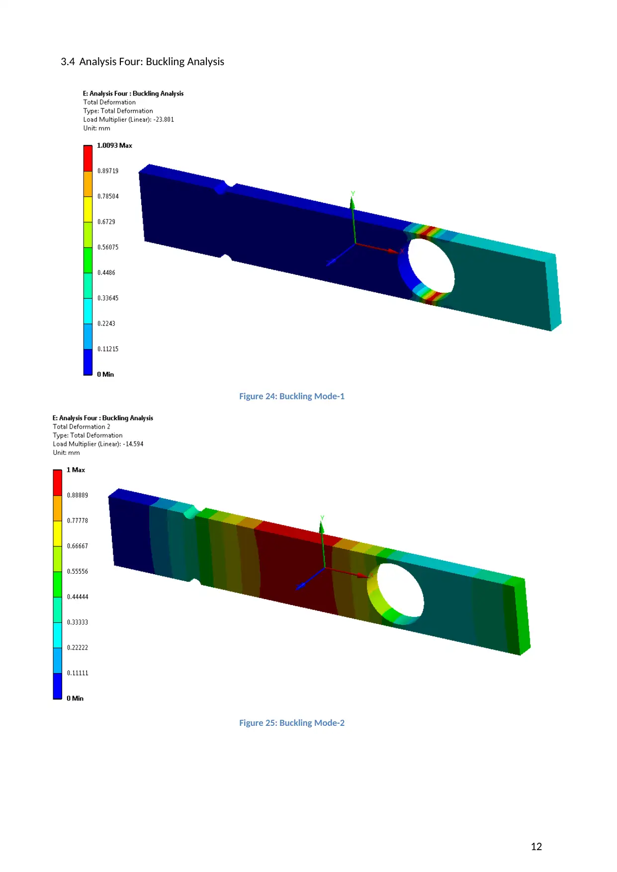
This project presents a Finite Element Analysis (FEA) of a plate, conducted using ANSYS Workbench. The analysis includes detailed investigations into the plate's behavior under various loading conditions and constraints. The project encompasses structural analysis, modal analysis, and buckling analysis. The structural analysis explores the plate's response to axial loading and bending, presenting deformation patterns and stress distributions. The modal analysis examines the plate's natural frequencies and mode shapes, providing insights into its dynamic characteristics. Finally, the buckling analysis determines the critical loads at which the plate may experience instability. The document includes screenshots of the model, meshing, boundary conditions, and results, offering a comprehensive understanding of the FEA process. This assignment is provided by a student on Desklib, a platform that offers AI-driven study tools and resources for students.
Document Page
Work Package 2
CIVL9001 Finite Element Analysis
1. Solid Model Using ANSYS Workbench
As directed in the Youtube Reference video, a sketch was created in DesignModeler. Later the
dimensions were modified as mentioned in the Assignment. Below is the screenshot of the same.
Figure 1: Thin Plate sketch in DesignModeler
The variable dimensions for this case were:
Plate width =1000mm; Plate Height = 160mm; Hole Position = 200mm ; Hole Rafius =70mm; Notch Radii
=15.5 mm and Notch Offset =4.5mm.
Figure 2: Dimensions in Ansys Sketch
The 3D Model for the Thin Plate is as below:
1
tabler-icon-diamond-filled.svg

Paraphrase This Document

Need a fresh take? Get an instant paraphrase of this document with our AI Paraphraser
Document Page
Figure 3: 3D-CAD Model
2. Meshing
The part is meshed with Hex-Dominant Element. The total Element count is 12188 elements and
56193 nodes.
Figure 4: Meshed Model
3. Structural Analyses
2
Document Page
Figure 5: Structural Analyses in Ansys Workbench
3.1 Analysis One : Axial Loading
3.1.1 Loading and Boundary Constraints
Figure 6: Boundary Constraint - Fixed End
Figure 7: Axial Load of 560,000 N
3
Document Page
3.1.2 Results
4
Figure 8: Total Deformation
Figure 9: Total Deformation
tabler-icon-diamond-filled.svg

Paraphrase This Document

Need a fresh take? Get an instant paraphrase of this document with our AI Paraphraser
Document Page
Figure 10: Equivalent von Mises Stress
Figure 11: Equivalent von Mises Stress
5
Document Page
3.2 Analysis Two: Bending Loading
3.2.1 Loading and Boundary Constraints
Figure 12: Boundary Constraint - Fixed End
Figure 13: Moment Load at free end
We have assumed arbitrary value of 560 Nm of Moment load at the free end.
6
Document Page
3.2.2 Results
Figure 14: Total Deformation
Figure 15: Total Deformation
7
tabler-icon-diamond-filled.svg

Paraphrase This Document

Need a fresh take? Get an instant paraphrase of this document with our AI Paraphraser
Document Page
8
Figure 16: Equivalent von Mises Stress
Figure 17: Equivalent von Mises Stress
Document Page
3.3 Analysis Three: Modal Analysis
An unconstrained Modal Analysis was performed and results for first six Modes are shown below:
Figure 18: Mode-1
9
Figure 19: Mode-2
Document Page
10
Figure 20: Mode-3
Figure 21: Mode-4
tabler-icon-diamond-filled.svg

Paraphrase This Document

Need a fresh take? Get an instant paraphrase of this document with our AI Paraphraser
Document Page
Figure 22: Mode-5
Figure 23: Mode-6
11
Document Page
3.4 Analysis Four: Buckling Analysis
Figure 24: Buckling Mode-1
Figure 25: Buckling Mode-2
12
chevron_up_icon
1 out of 14
circle_padding
hide_on_mobile
zoom_out_icon
[object Object]