ME5013: Comprehensive Analysis of a Simply Supported Beam (FEA Report)
VerifiedAdded on 2023/01/06
|17
|2029
|41
Report
AI Summary
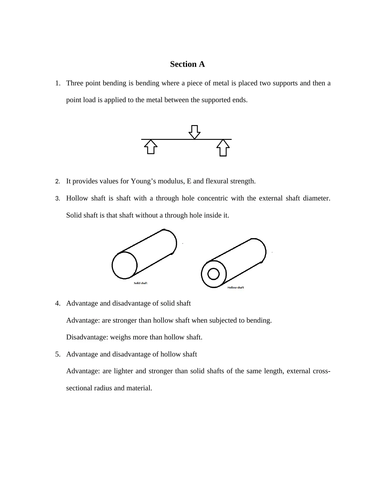
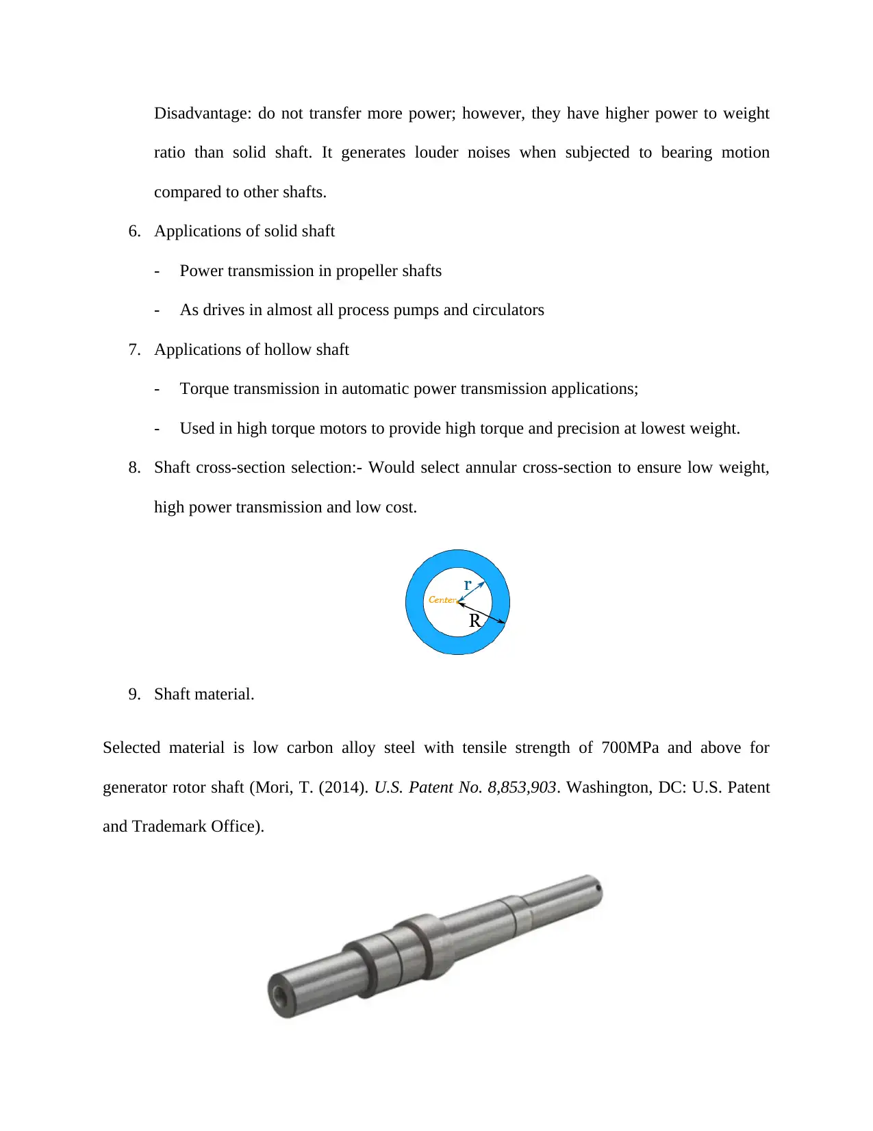
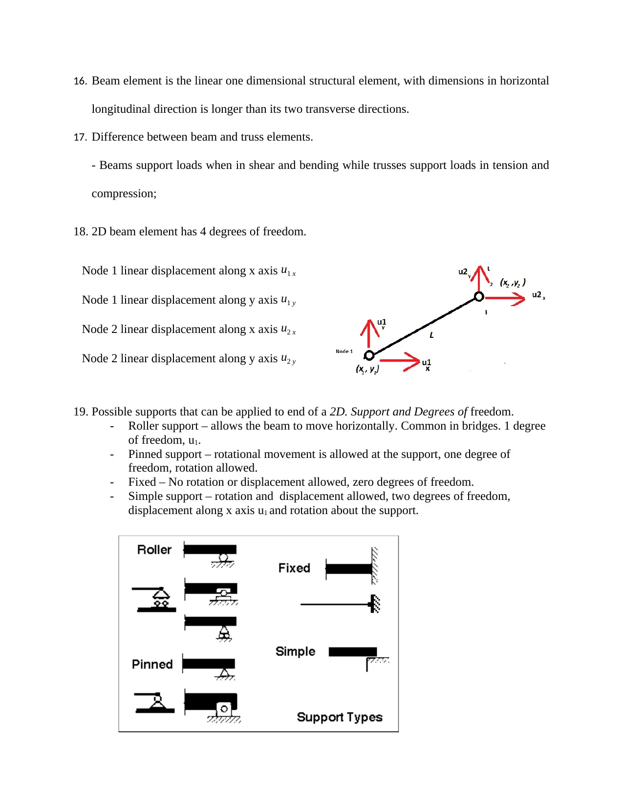
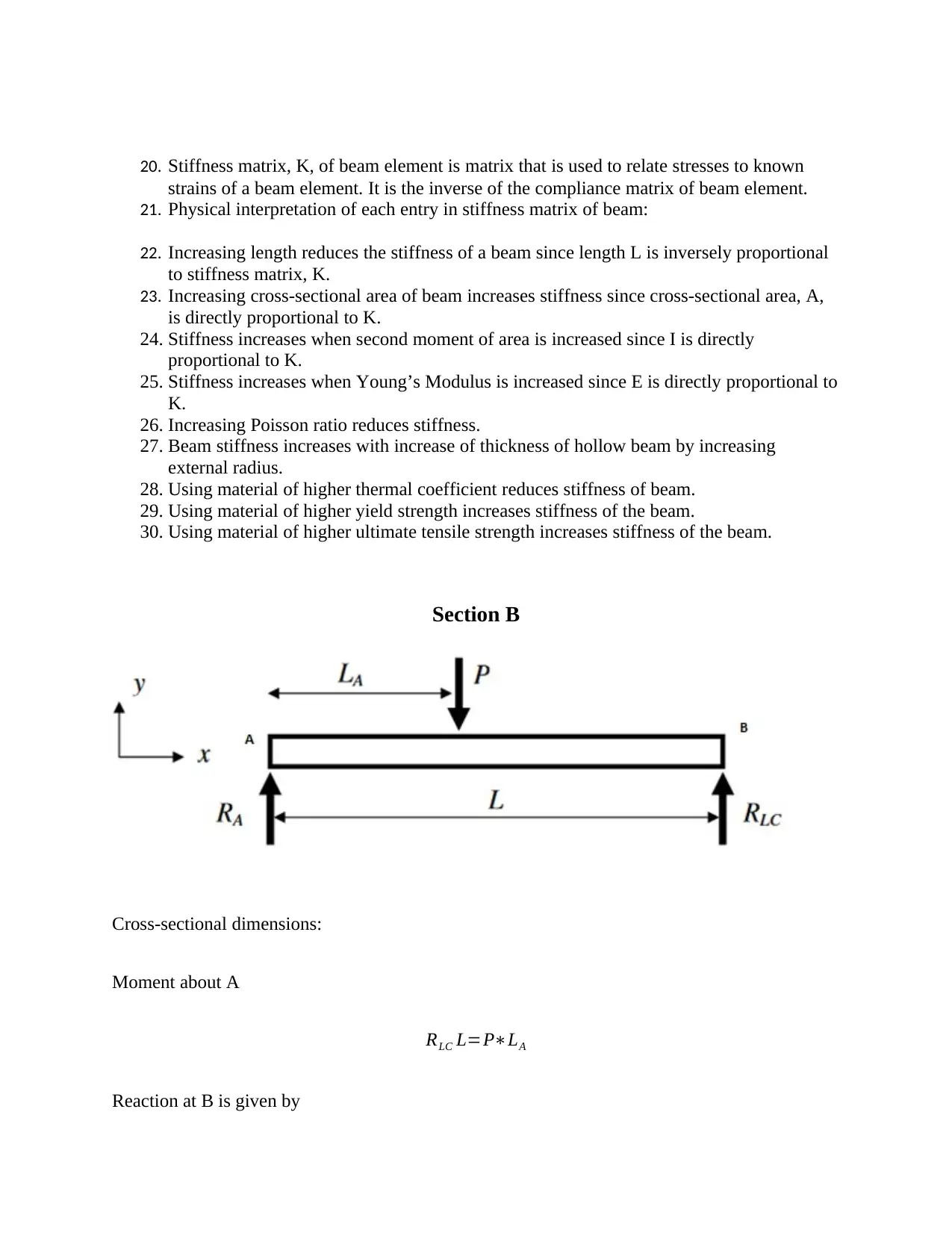
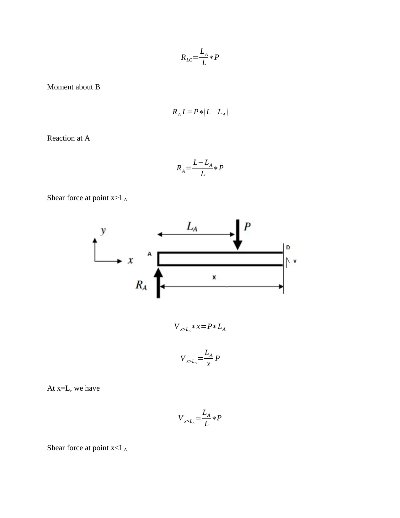
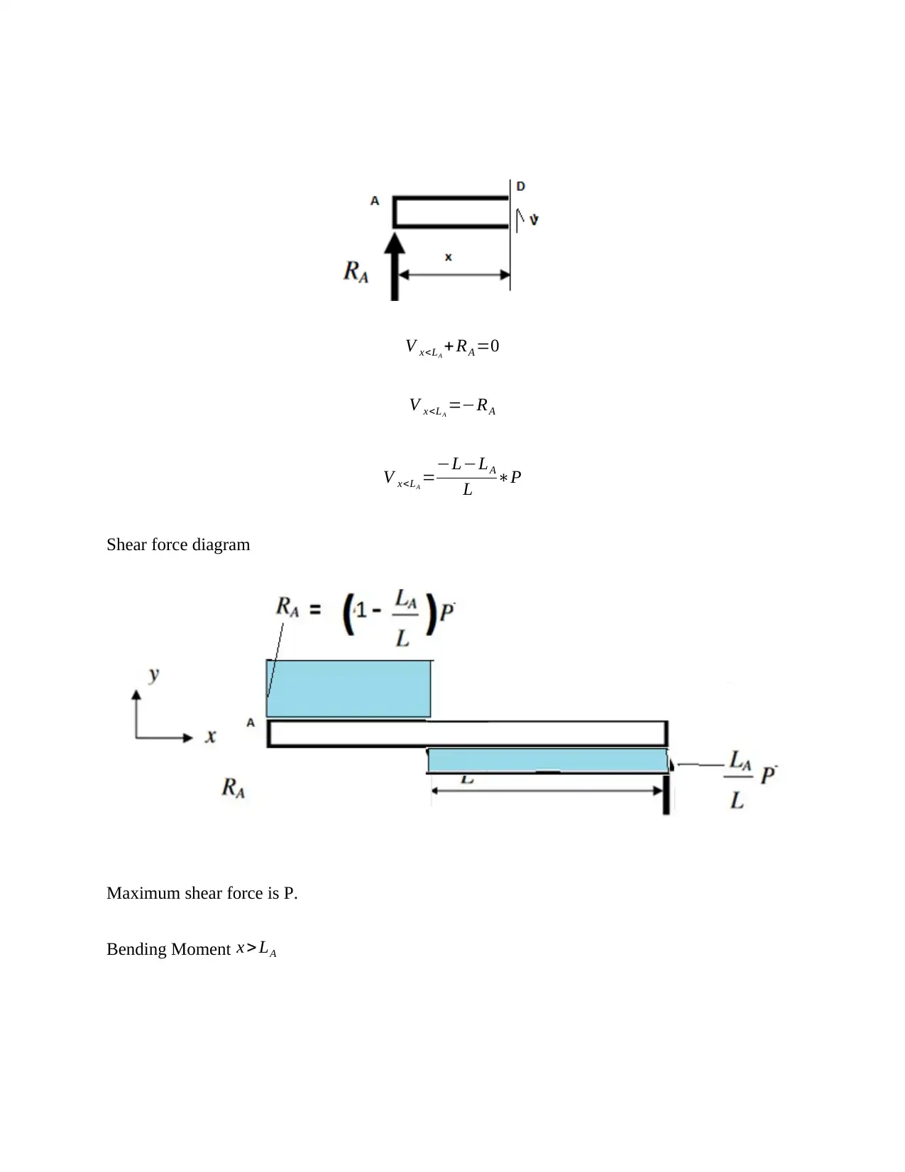
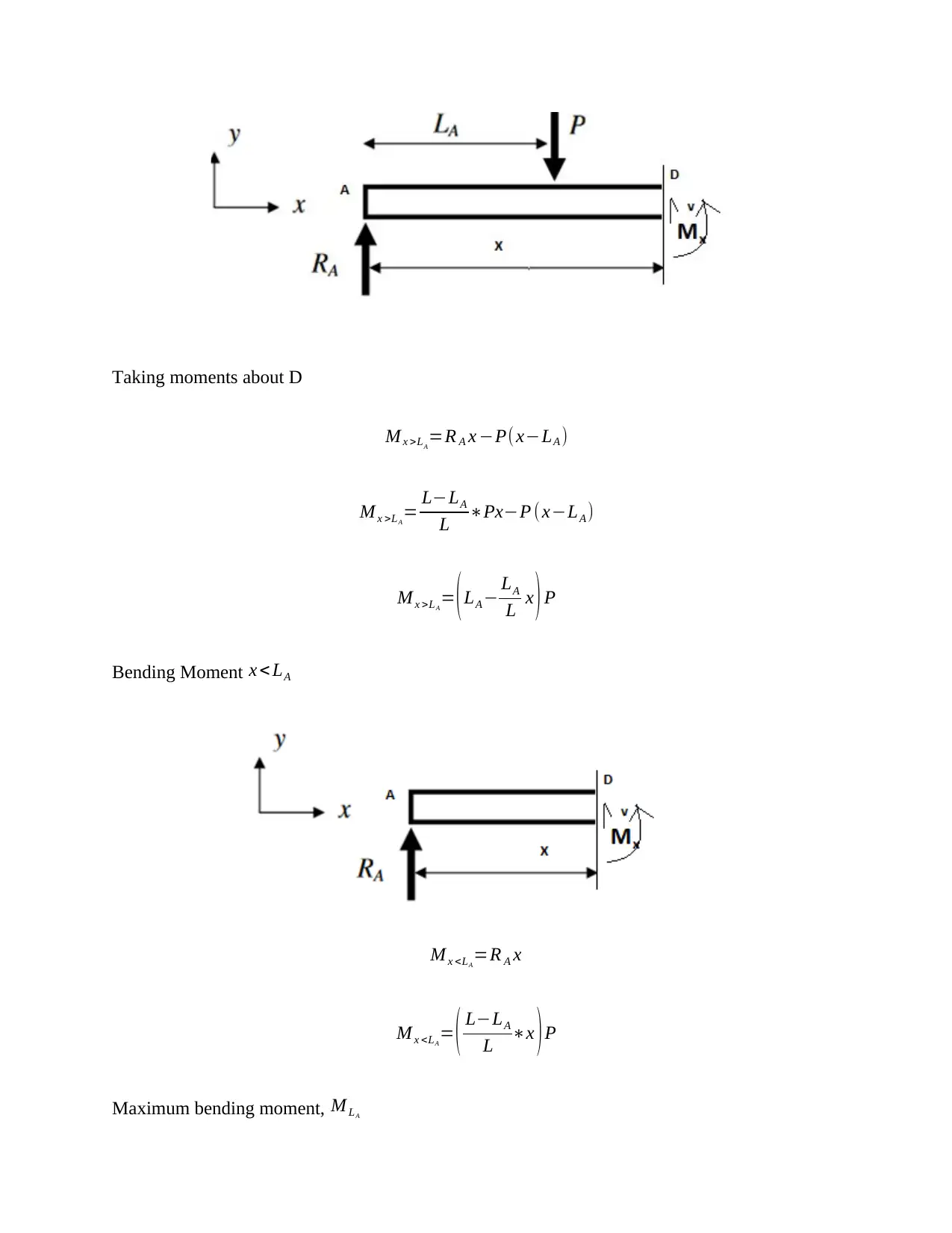
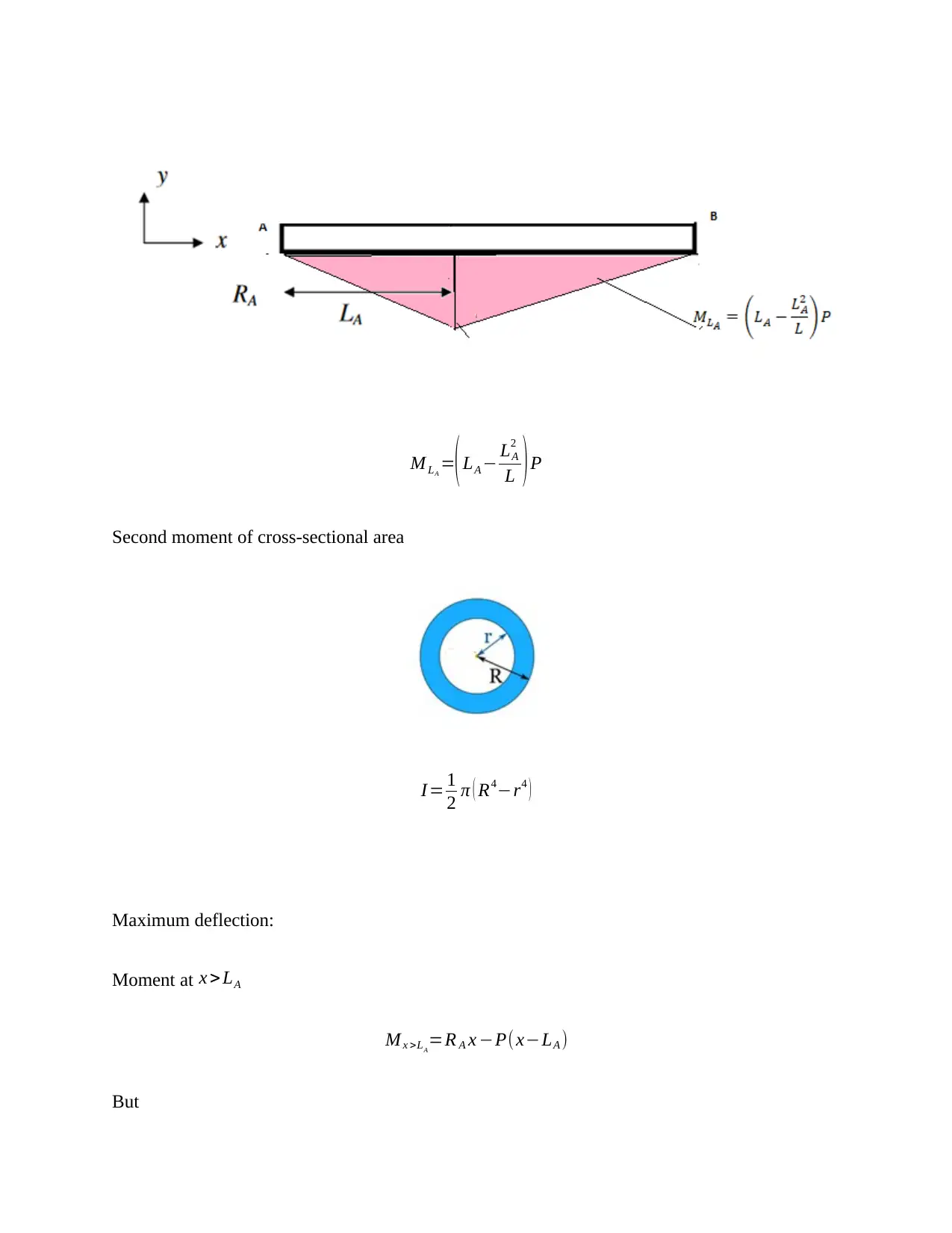
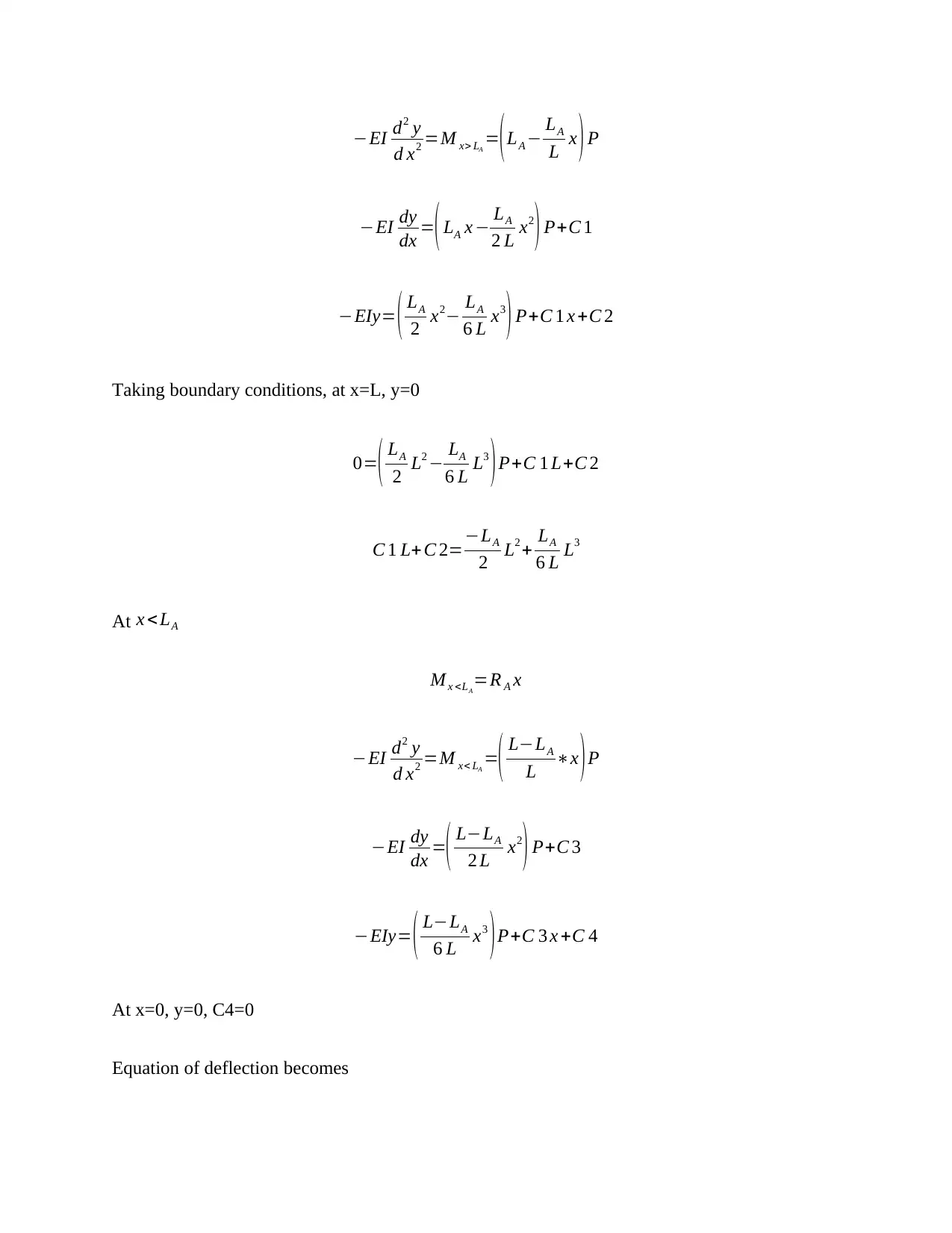
This report presents a detailed analysis of a simply supported, hollow beam subjected to a three-point bending test. The analysis incorporates analytical calculations, numerical methods, and finite element analysis (FEA) using CAD/CAE tools. The beam, made of structural steel, is 8000mm long and subject to a 7000N vertical load. The report covers key concepts such as bending moment, shear force, deflection, and stiffness, examining the influence of various parameters like cross-sectional dimensions, material properties, and support conditions. Calculations include determining reactions, shear forces, and bending moments, as well as the second moment of area and maximum deflection. The report also explores the stiffness matrix and its relationship to beam parameters. The findings are presented in a structured format, including figures and equations, to illustrate the beam's behavior under load, and to ensure the stress constraint of 140MPa and a deflection constraint of L/1000 are met. The analysis is based on the application of a ceramic coated aluminum allow shaft and aluminum alloy shaft.
Contribute Materials
Your contribution can guide someone’s learning journey. Share your
documents today.

Section A
1. Three point bending is bending where a piece of metal is placed two supports and then a
point load is applied to the metal between the supported ends.
2. It provides values for Young’s modulus, E and flexural strength.
3. Hollow shaft is shaft with a through hole concentric with the external shaft diameter.
Solid shaft is that shaft without a through hole inside it.
4. Advantage and disadvantage of solid shaft
Advantage: are stronger than hollow shaft when subjected to bending.
Disadvantage: weighs more than hollow shaft.
5. Advantage and disadvantage of hollow shaft
Advantage: are lighter and stronger than solid shafts of the same length, external cross-
sectional radius and material.
Secure Best Marks with AI Grader
Need help grading? Try our AI Grader for instant feedback on your assignments.

Disadvantage: do not transfer more power; however, they have higher power to weight
ratio than solid shaft. It generates louder noises when subjected to bearing motion
compared to other shafts.
6. Applications of solid shaft
- Power transmission in propeller shafts
- As drives in almost all process pumps and circulators
7. Applications of hollow shaft
- Torque transmission in automatic power transmission applications;
- Used in high torque motors to provide high torque and precision at lowest weight.
8. Shaft cross-section selection:- Would select annular cross-section to ensure low weight,
high power transmission and low cost.
9. Shaft material.
Selected material is low carbon alloy steel with tensile strength of 700MPa and above for
generator rotor shaft (Mori, T. (2014). U.S. Patent No. 8,853,903. Washington, DC: U.S. Patent
and Trademark Office).

Aluminum alloy EN AW 6061/6060 material for precision shaft to be used with linear plain
bearings. Examples include ceramic coated aluminum precision shafts. (Choi, Y., Kim, D. U.,
Kang, B. Y., Park, D. K., Lee, D. J., Lee, S. W., & Shin, H. T. (2013). Forming of the precision
aluminum tube for a light weight propeller shaft. Journal of Mechanical Science and
Technology, 27(11), 3445-3449.)
Figure 1: Ceramic coated aluminum allow
shaft Figure 2: Aluminum alloy shaft
10. Finite element analysis of a structure is the analysis of a structure by hypothetically
subdividing into an assembly of small parts called elements assumed to be connected to one
another at joints called nodes.
11. Preprocessing is model preparation by defining problem. It includes: design of model,
creation of mesh, element selection, defining geometrical properties, selecting material,
defining constraints and boundary conditions and loads.
12. Post-processing refers to evaluation and interpretation of the results or review of the results.
13. Degree of freedom is the number of independent coordinates a structure can move.
14. Reaction force is a force opposite and normal to any action force in accordance with
Newton’s Third Law of motion.
15. Reaction force should be equal and opposite action force.

16. Beam element is the linear one dimensional structural element, with dimensions in horizontal
longitudinal direction is longer than its two transverse directions.
17. Difference between beam and truss elements.
- Beams support loads when in shear and bending while trusses support loads in tension and
compression;
18. 2D beam element has 4 degrees of freedom.
Node 1 linear displacement along x axis u1 x
Node 1 linear displacement along y axis u1 y
Node 2 linear displacement along x axis u2 x
Node 2 linear displacement along y axis u2 y
19. Possible supports that can be applied to end of a 2D. Support and Degrees of freedom.
- Roller support – allows the beam to move horizontally. Common in bridges. 1 degree
of freedom, u1.
- Pinned support – rotational movement is allowed at the support, one degree of
freedom, rotation allowed.
- Fixed – No rotation or displacement allowed, zero degrees of freedom.
- Simple support – rotation and displacement allowed, two degrees of freedom,
displacement along x axis u1 and rotation about the support.
Secure Best Marks with AI Grader
Need help grading? Try our AI Grader for instant feedback on your assignments.

20. Stiffness matrix, K, of beam element is matrix that is used to relate stresses to known
strains of a beam element. It is the inverse of the compliance matrix of beam element.
21. Physical interpretation of each entry in stiffness matrix of beam:
22. Increasing length reduces the stiffness of a beam since length L is inversely proportional
to stiffness matrix, K.
23. Increasing cross-sectional area of beam increases stiffness since cross-sectional area, A,
is directly proportional to K.
24. Stiffness increases when second moment of area is increased since I is directly
proportional to K.
25. Stiffness increases when Young’s Modulus is increased since E is directly proportional to
K.
26. Increasing Poisson ratio reduces stiffness.
27. Beam stiffness increases with increase of thickness of hollow beam by increasing
external radius.
28. Using material of higher thermal coefficient reduces stiffness of beam.
29. Using material of higher yield strength increases stiffness of the beam.
30. Using material of higher ultimate tensile strength increases stiffness of the beam.
Section B
Cross-sectional dimensions:
Moment about A
RLC L=P∗LA
Reaction at B is given by

RLC= LA
L ∗P
Moment about B
RA L=P∗( L−LA )
Reaction at A
RA = L−LA
L ∗P
Shear force at point x>LA
V x>LA
∗x=P∗LA
V x>LA
= LA
x P
At x=L, we have
V x>LA
= LA
L ∗P
Shear force at point x<LA
L ∗P
Moment about B
RA L=P∗( L−LA )
Reaction at A
RA = L−LA
L ∗P
Shear force at point x>LA
V x>LA
∗x=P∗LA
V x>LA
= LA
x P
At x=L, we have
V x>LA
= LA
L ∗P
Shear force at point x<LA

V x<LA
+ RA =0
V x<LA
=−RA
V x<LA
=−L−LA
L ∗P
Shear force diagram
Maximum shear force is P.
Bending Moment x > LA
+ RA =0
V x<LA
=−RA
V x<LA
=−L−LA
L ∗P
Shear force diagram
Maximum shear force is P.
Bending Moment x > LA
Paraphrase This Document
Need a fresh take? Get an instant paraphrase of this document with our AI Paraphraser

Taking moments about D
M x >LA
=R A x −P( x−LA )
M x >LA
= L−LA
L ∗Px−P (x−LA )
M x >LA
= (LA − LA
L x ) P
Bending Moment x < LA
M x <LA
=R A x
M x <LA
= ( L−LA
L ∗x )P
Maximum bending moment, M LA
M x >LA
=R A x −P( x−LA )
M x >LA
= L−LA
L ∗Px−P (x−LA )
M x >LA
= (LA − LA
L x ) P
Bending Moment x < LA
M x <LA
=R A x
M x <LA
= ( L−LA
L ∗x )P
Maximum bending moment, M LA

M LA
=( LA − LA
2
L ) P
Second moment of cross-sectional area
I = 1
2 π ( R4−r4 )
Maximum deflection:
Moment at x > LA
M x >LA
=R A x −P( x−LA )
But
=( LA − LA
2
L ) P
Second moment of cross-sectional area
I = 1
2 π ( R4−r4 )
Maximum deflection:
Moment at x > LA
M x >LA
=R A x −P( x−LA )
But

−EI d2 y
d x2 =M x> LA
=(LA − LA
L x ) P
−EI dy
dx =( LA x − LA
2 L x2
) P+C 1
−EIy= ( LA
2 x2− LA
6 L x3
) P+C 1 x +C 2
Taking boundary conditions, at x=L, y=0
0=( LA
2 L2 − LA
6 L L3
)P+C 1 L+C 2
C 1 L+ C 2=−LA
2 L2 + LA
6 L L3
At x < LA
M x <LA
=R A x
−EI d2 y
d x2 =M x< LA
=( L−LA
L ∗x ) P
−EI dy
dx =( L−LA
2 L x2
) P+C 3
−EIy= ( L−LA
6 L x3
)P+C 3 x +C 4
At x=0, y=0, C4=0
Equation of deflection becomes
Secure Best Marks with AI Grader
Need help grading? Try our AI Grader for instant feedback on your assignments.

−EIy= ( L−LA
6 L x3
)P+C 3 x
At x=LA,
−EIy= ( L−LA
6 L LA
3
) P+C 3 LA
−EIy= ( LA
2 LA
2 − LA
6 L LA
3
) P+C 1 LA +C 2
And
−EI dy
dx =( L−LA
2 L LA
2
)P+C 3
−EI dy
dx =( LA
2− LA
2 L LA
2
) P+C 1
C 2=( 1
6 LA
− LA
2
2 ) P
Solving for C1
C 1 L+ C 2=−LA
2 L2 + LA
6 L L3
C 1 L=−LA
2 L2 + LA
6 L L3−C 2
C 1=−LA
2 L+ LA
6 L L2− ( 1
6 LA
− LA
2
2 ) P
Deflection equation becomes

−EIy= ( LA
2 x2− LA
6 L x3
) P+C 1 x +C 2
−EIy= ( LA
2 x2− LA
6 L x3
) P+
( LA
2 L+ LA
6 L L2− ( 1
6 LA
− LA
2
2 )P )x + ( 1
6 LA
− LA
2
2 )P
Gradient becomes
−EI dy
dx =( LA x − LA
2 L x2
) P+C 1
−EI dy
dx =( LA x − LA
2 L x2
) P− LA
2 L+ LA
6 L L2−( 1
6 LA
− LA
2
2 ) P
At maximum deflection
−EI dy
dx =0=(LA x− LA
2 L x2
)P− LA
2 L+ LA
6 L L2−
( 1
6 LA
− LA
2
2 ) P
¿− LA
2 L x2+ LA x−
( LA
2 P L− LA
6 P L+( 1
6 LA
− LA
2
2 ) )
¿ x2−2 Lx+ ( L2
P − L2
3 P + L
3 LA
2 −L LA )
Let ( L2
P − L3
3 P + + L
3 LA
2 −L LA )=k
x2−2 Lx+ k=0
Maximum deflection occurs at
2 x2− LA
6 L x3
) P+C 1 x +C 2
−EIy= ( LA
2 x2− LA
6 L x3
) P+
( LA
2 L+ LA
6 L L2− ( 1
6 LA
− LA
2
2 )P )x + ( 1
6 LA
− LA
2
2 )P
Gradient becomes
−EI dy
dx =( LA x − LA
2 L x2
) P+C 1
−EI dy
dx =( LA x − LA
2 L x2
) P− LA
2 L+ LA
6 L L2−( 1
6 LA
− LA
2
2 ) P
At maximum deflection
−EI dy
dx =0=(LA x− LA
2 L x2
)P− LA
2 L+ LA
6 L L2−
( 1
6 LA
− LA
2
2 ) P
¿− LA
2 L x2+ LA x−
( LA
2 P L− LA
6 P L+( 1
6 LA
− LA
2
2 ) )
¿ x2−2 Lx+ ( L2
P − L2
3 P + L
3 LA
2 −L LA )
Let ( L2
P − L3
3 P + + L
3 LA
2 −L LA )=k
x2−2 Lx+ k=0
Maximum deflection occurs at

x= 2 L ± √ 4 L2−4 k
2
x=L ± √ L2−k
For a standard hollow beam of outside diameter 33.7mm with thickness of 3.0mm, and length
2m with point load of 20N at 0.5m from end A moment of inertia I is found as:
I = 1
2 π ( R4−r4 )
I = 1
2 π (( 33.7
2 )
4
− ( 33.7−2∗3
2 ) 4
) ×10−12 m4
I=6.88261917 ×10⁻⁸ m4
Maximum shear force
This is equal to P=20N.
Maximum bending moment
M LA
=( LA − LA
2
L ) P
M LA
=( 0.5− 0.52
2 )∗20
M LA
=7.5 Nm
Deflection
2
x=L ± √ L2−k
For a standard hollow beam of outside diameter 33.7mm with thickness of 3.0mm, and length
2m with point load of 20N at 0.5m from end A moment of inertia I is found as:
I = 1
2 π ( R4−r4 )
I = 1
2 π (( 33.7
2 )
4
− ( 33.7−2∗3
2 ) 4
) ×10−12 m4
I=6.88261917 ×10⁻⁸ m4
Maximum shear force
This is equal to P=20N.
Maximum bending moment
M LA
=( LA − LA
2
L ) P
M LA
=( 0.5− 0.52
2 )∗20
M LA
=7.5 Nm
Deflection
Paraphrase This Document
Need a fresh take? Get an instant paraphrase of this document with our AI Paraphraser

k =
( L2
P − L3
3 P + + L
3 LA
2 −L LA )
k =
( 22
20 − 23
3∗20 + 2
3∗( 0.5 )2 −2∗0.25 )
k =2.2333
Maximum deflection occurs at
x=L ± √ L2−k
x=2 ± √ 22−2.2333
x=2 ±1.32916
x=0.57084
Maximum deflection
−EIy= ( 0.5
2 ¿ 0.570842− 0.5
6∗2∗0.570843
)∗20+ ( 0.5
2 ∗2+ 0.5
6∗2 22−( 1
6∗0.5 − 0.52
2 )∗20 )∗0.57084 +
( 1
6∗0.52 − 0.52
2 )
y=−0.1231× 10⁻² m

Section C
Element 1 Element 2
Reaction at A
RA = P (L−LA )
L
RA = 20(2−0.5)
2
RA =15 N
Element 1 Element 2
Reaction at A
RA = P (L−LA )
L
RA = 20(2−0.5)
2
RA =15 N

Shear force at B
VB=P−RA
¿ 20−15
¿ 5 N
Momement, MA
M A =VB∗L
2 −P∗LA
¿ 5∗2
2 −20∗0.5
¿−10 Nm
Element 1 deflection
−10= EI
L θA + EI
L θB
Reaction at C
RC=−VB=−5 N
Momement, MC
M A =VB∗1
¿ 5∗1
¿ 5 Nm
VB=P−RA
¿ 20−15
¿ 5 N
Momement, MA
M A =VB∗L
2 −P∗LA
¿ 5∗2
2 −20∗0.5
¿−10 Nm
Element 1 deflection
−10= EI
L θA + EI
L θB
Reaction at C
RC=−VB=−5 N
Momement, MC
M A =VB∗1
¿ 5∗1
¿ 5 Nm
Secure Best Marks with AI Grader
Need help grading? Try our AI Grader for instant feedback on your assignments.

5= EI
L θB+ EI
L θC
L θB+ EI
L θC
1 out of 17

Your All-in-One AI-Powered Toolkit for Academic Success.
+13062052269
info@desklib.com
Available 24*7 on WhatsApp / Email
Unlock your academic potential
© 2024 | Zucol Services PVT LTD | All rights reserved.