Finite Element Method: Stress & Deflection in Structural Elements
VerifiedAdded on 2023/05/30
|22
|4676
|451
Homework Assignment
AI Summary
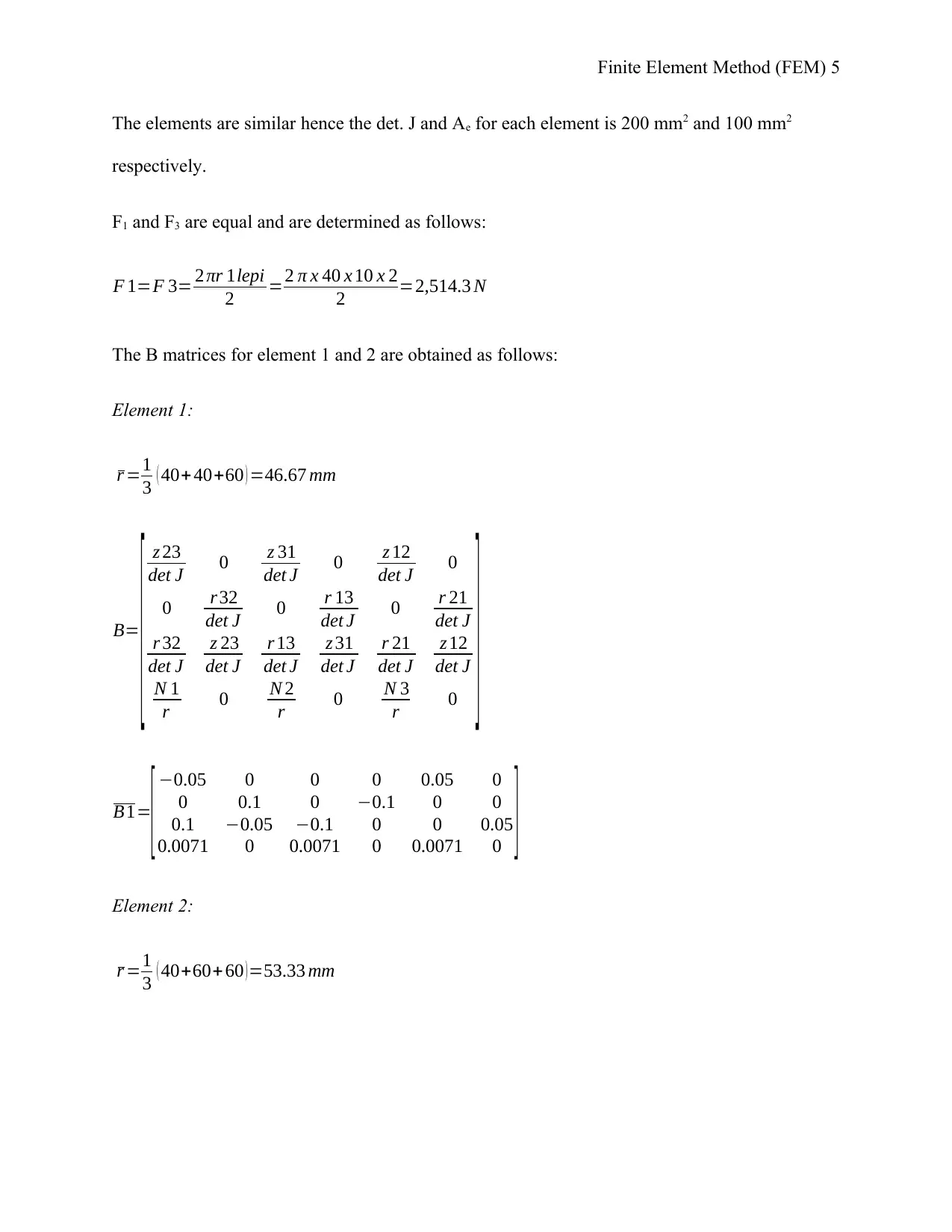
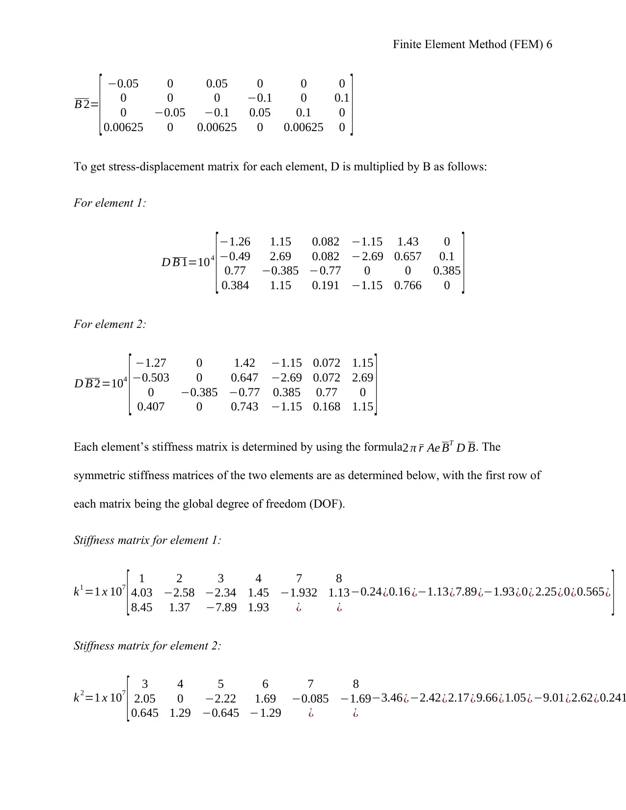
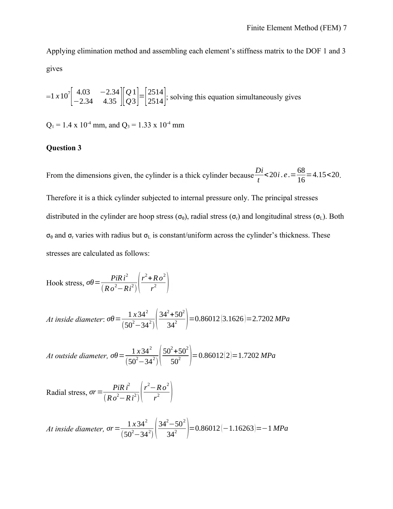
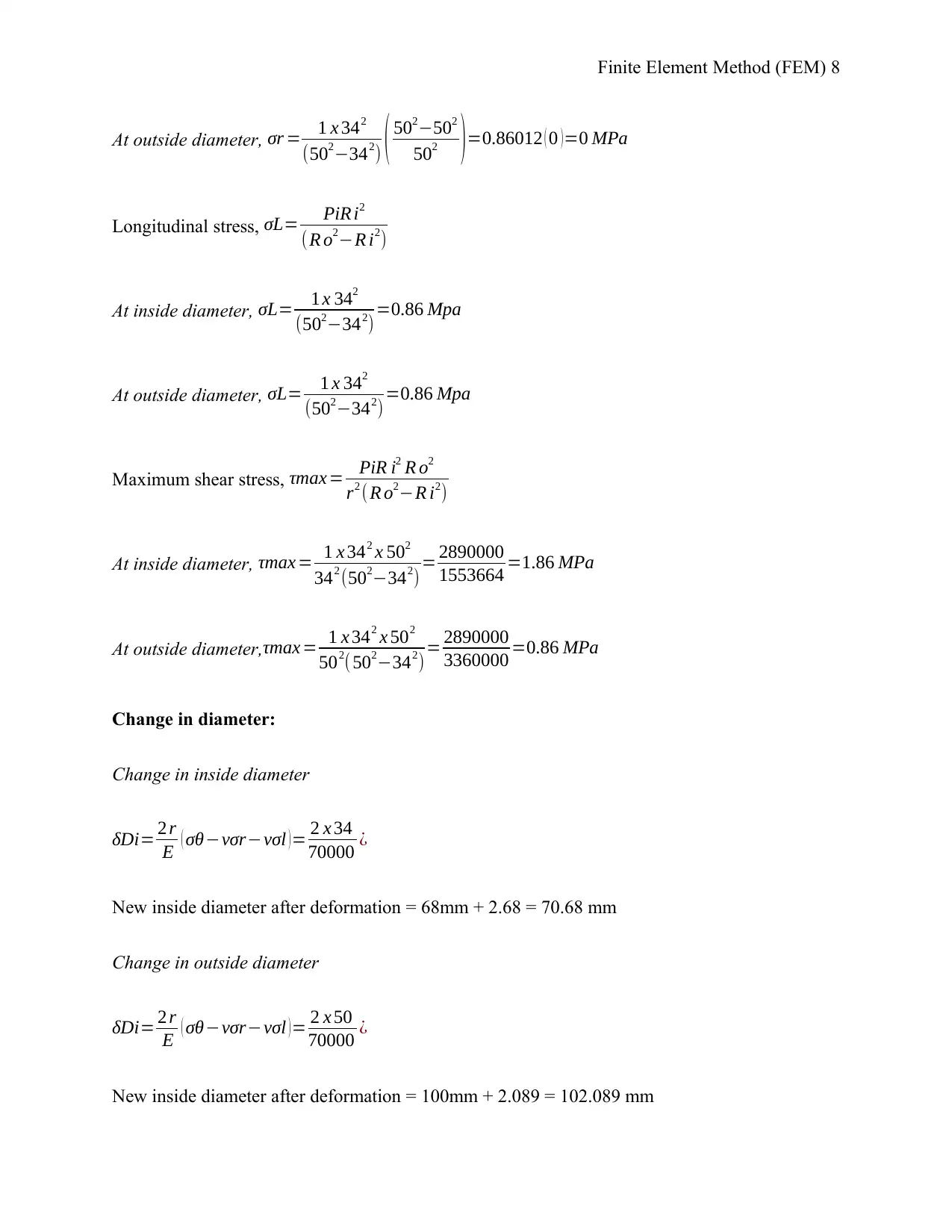
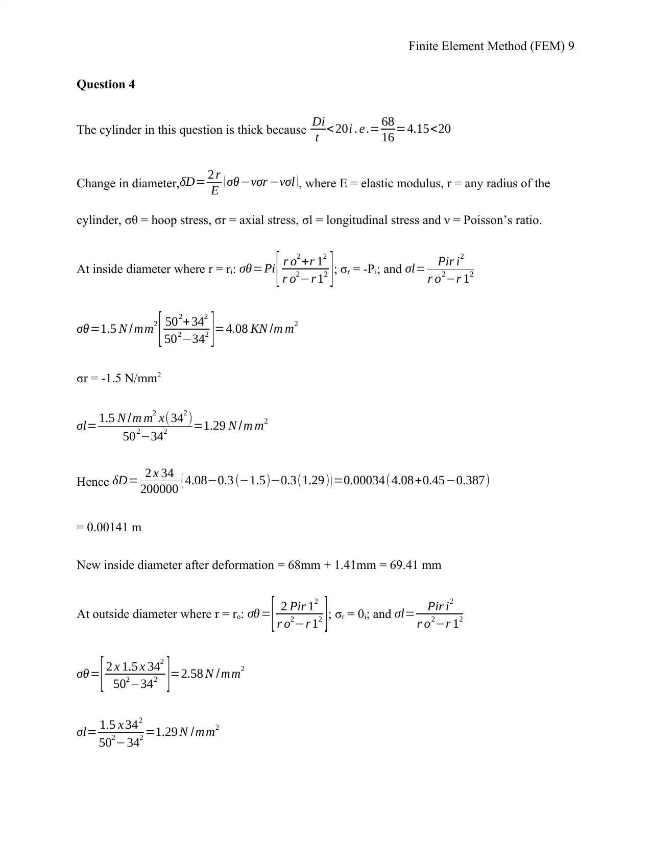
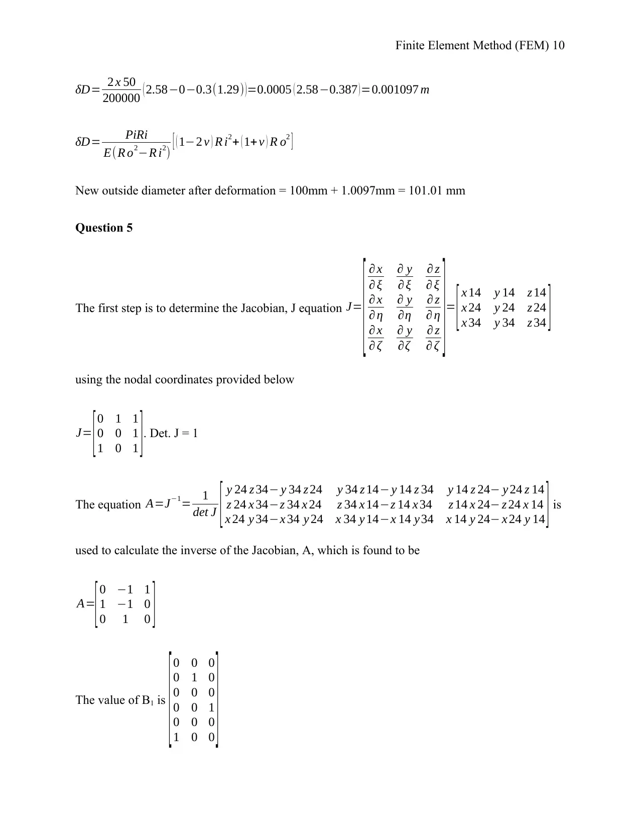
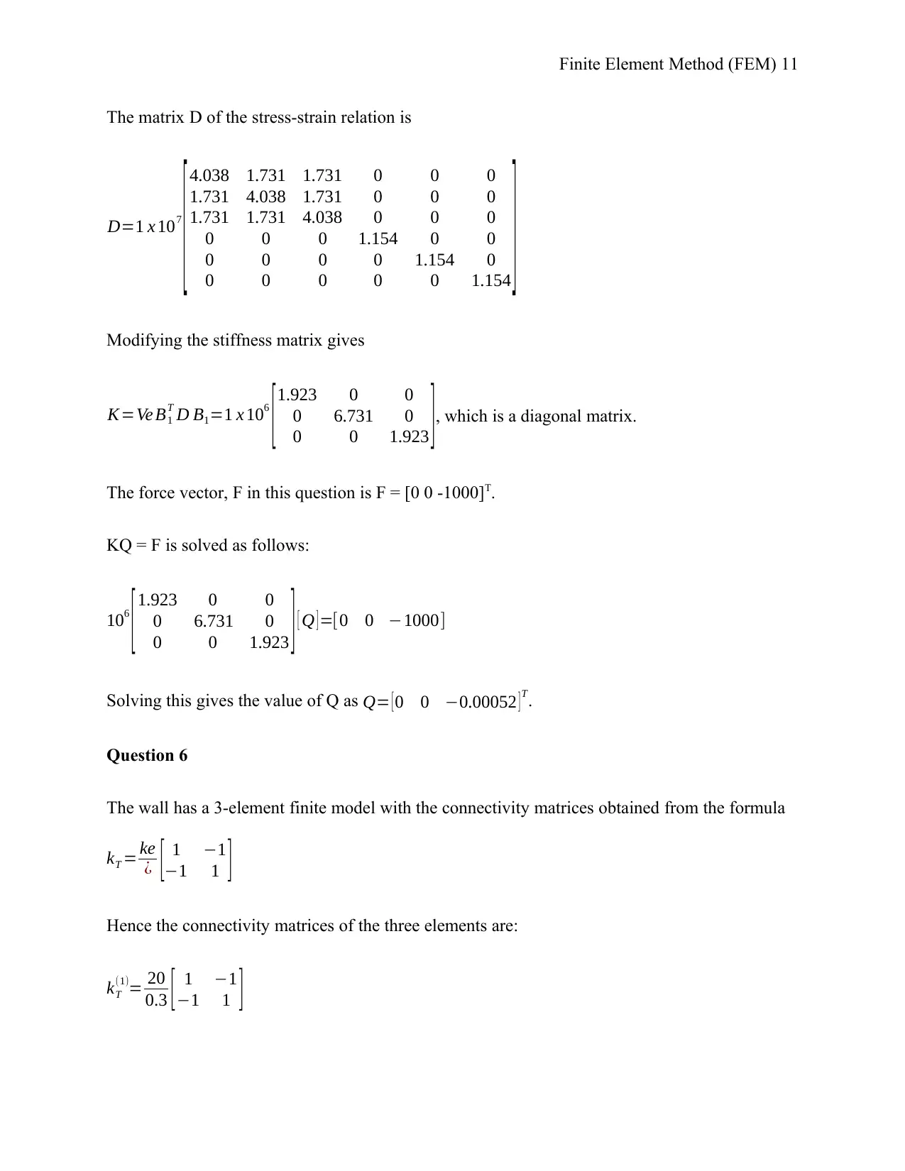
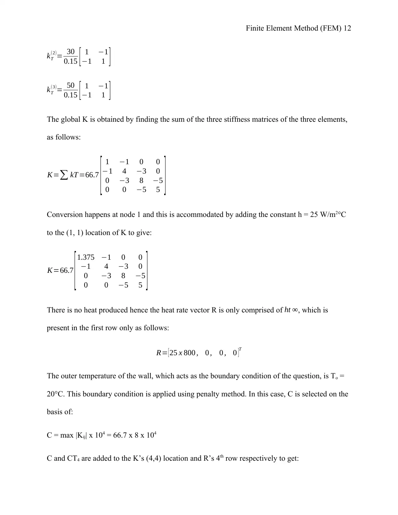
This assignment solution focuses on the Finite Element Method (FEM) and covers several structural mechanics problems. It includes determining the slope and vertical deflection of a beam under a uniformly distributed load using element matrices and the elimination method. The solution also involves stress analysis of thick cylinders subjected to internal pressure, calculating hoop stress, radial stress, longitudinal stress, and maximum shear stress, as well as changes in diameter due to deformation. Furthermore, the assignment addresses displacement analysis of a four-node tetrahedral object under load, determining the Jacobian matrix and applying material properties to find nodal displacements. The final solutions provide detailed calculations and results for each problem.

Finite Element Method (FEM) 1
FINITE ELEMENT METHOD (FEM)
Name
Course
University
City/state
Date
FINITE ELEMENT METHOD (FEM)
Name
Course
University
City/state
Date
Paraphrase This Document
Need a fresh take? Get an instant paraphrase of this document with our AI Paraphraser

Finite Element Method (FEM) 2
Finite Element Method (FEM)
Question 1
Slope at 2 and 3
The three nodes form two elements that are considered in this question. The constraint of the
beam makes the following displacements to be zero: Q1 = Q2 = Q3 = Q5 = 0. However, Q4 and Q6
have to be determined. Since the sections and length of the two parts of the beam are equal, the
equation used to calculate the element matrices is:
k e= EI
l e3 [ 12 6≤¿−12 6≤¿ 6≤¿ 4 l e2 −6≤¿ 2l e2
−12 −6≤¿ 12 −6≤¿ 6≤¿ 2 l e2 −6≤¿ 4 l e2 ]
E = 200 GPa and I = 4 x 106 mm4
EI
l3 = ( 200 x 109 ) Pa∨N /m2 x ( 4 x 10⁻⁶ ) m4
13 m3 =8 x 10⁵ N /m
Effective length, le = 1
k1 =k2=8 x 10⁵
[ 12 6 −12 6
6 4 −6 2
−12 −6 12 −6
6 2 −6 4 ]
The global loads that are applied on the beam are calculated as follows:
F4 = −p l2
12 = 12 KNm x 12 m2
12 =−1,000 Nm
F6 = + p l2
12 = 12 KNm x 12 m2
12 =+1,000 Nm
Elimination method is used together with connectivity to give global stiffness as follows:

Finite Element Method (FEM) 3
K= [k 44
(1)+ k22
(2 ) k24
(2)
k42
(2) k 44
(2) ]=8 x 10⁵
[8 2
2 4 ]
The matrix equation for the slopes at 2 and 3 are:
= 8 x 10⁵
[8 2
2 4 ][Q 4
Q6 ]= [−1000
+1000 ]=
[64 x 105 16 x 105
16 x 105 32 x 105 ] [Q 4
Q 6 ]=[−1000
+1000 ]
= [ 64 x 105 16 x 105
16 x 105 32 x 105 ] [ Q 4
Q 6 ]= [ −1000
+1000 ]
= [64 x 105 Q 4+ 16 x 105 Q6
16 x 105 Q 4+ 32 x 105 Q 6 ]= [−1000
+ 1000 ]
Solving this simultaneously gives
[ Q 4
Q 6 ] = [−2.697 x 10⁻⁴
4.464 x 10⁻⁴ ]
Hence Q4 = -2.697 x 10⁻⁴ and Q6 = 4.464 x 10⁻⁴
Vertical deflection at midpoint of the uniformly distributed load
For the second element of the beam, q1 & q3 = 0, q2 = Q4, and q4 = Q6. Vertical deflection at the
midpoint of the second element is determined using ν = Hq at ξ = 0
ν=H 1 q 1+ ¿
2 H 2 q 2+ H 3 q 3+ ¿
2 H 4 q 6
Thus ν=0+ ¿
2 H 2Q 4 +0+ ¿
2 H 4 Q 6
=( 1
2 )( 1
4 ) (−2.679 x 10⁻⁴ ) + (1
2 )(−1
4 ) ( 4.464 x 10⁻⁴ )
⊘ This is a preview!⊘
Do you want full access?
Subscribe today to unlock all pages.

Trusted by 1+ million students worldwide

Finite Element Method (FEM) 4
= (-3.348 x 10⁻⁵ m) + (-5.58 x 10⁻⁵ m) = 8.928 x 10⁻⁵ m = -0.08928 mm
Question 2
Elastic modulus, E = 200 GPa; Poisson’s ratio, ν = 0.3
The connectivity and coordinates tables for this question are as follows:
Coordinates
Node r z
1 40 10
2 40 0
3 60 0
4 60 10
Connectivity
Element 1 2 3
1 1 2 4
2 1 3 4
D= E (1−v)
(1+ v )(1−2 v )
[ 1 v
1−v 0 v
1−v
v
1−v 1 0 v
1−v
0 0 1−2 v
2(1−v ) 0
v
1−v
v
1−v 0 1 ]Substituting the values of E = 200 GPa and ν = 0.3 gives the value of D as
D=
[2.69 x 10⁵ 1.15 x 10⁵ 0 1.15 x 10⁵
1.15 x 10⁵ 2.69 x 10⁵ 0 1.15 x 10⁵
0 0 7.7 x 10⁴ 0
1.15 x 10⁵ 1.15 x 10⁵ 0 2.69 x 10⁵ ]
Paraphrase This Document
Need a fresh take? Get an instant paraphrase of this document with our AI Paraphraser

Finite Element Method (FEM) 5
The elements are similar hence the det. J and Ae for each element is 200 mm2 and 100 mm2
respectively.
F1 and F3 are equal and are determined as follows:
F 1=F 3= 2 πr 1lepi
2 =2 π x 40 x 10 x 2
2 =2,514.3 N
The B matrices for element 1 and 2 are obtained as follows:
Element 1:
r =1
3 ( 40+ 40+60 ) =46.67 mm
B=
[ z 23
det J 0 z 31
det J 0 z 12
det J 0
0 r 32
det J 0 r 13
det J 0 r 21
det J
r 32
det J
z 23
det J
r 13
det J
z 31
det J
r 21
det J
z 12
det J
N 1
r 0 N 2
r 0 N 3
r 0 ]
B1=
[ −0.05 0 0 0 0.05 0
0 0.1 0 −0.1 0 0
0.1 −0.05 −0.1 0 0 0.05
0.0071 0 0.0071 0 0.0071 0 ]
Element 2:
r =1
3 ( 40+60+ 60 )=53.33 mm

Finite Element Method (FEM) 6
B 2=
[ −0.05 0 0.05 0 0 0
0 0 0 −0.1 0 0.1
0 −0.05 −0.1 0.05 0.1 0
0.00625 0 0.00625 0 0.00625 0 ]
To get stress-displacement matrix for each element, D is multiplied by B as follows:
For element 1:
D B 1=104
[ −1.26 1.15 0.082 −1.15 1.43 0
−0.49 2.69 0.082 −2.69 0.657 0.1
0.77 −0.385 −0.77 0 0 0.385
0.384 1.15 0.191 −1.15 0.766 0 ]
For element 2:
D B 2=104
[ −1.27 0 1.42 −1.15 0.072 1.15
−0.503 0 0.647 −2.69 0.072 2.69
0 −0.385 −0.77 0.385 0.77 0
0.407 0 0.743 −1.15 0.168 1.15 ]
Each element’s stiffness matrix is determined by using the formula 2 π r Ae BT D B. The
symmetric stiffness matrices of the two elements are as determined below, with the first row of
each matrix being the global degree of freedom (DOF).
Stiffness matrix for element 1:
k1 =1 x 10⁷
[ 1 2 3 4 7 8
4.03 −2.58 −2.34 1.45 −1.932 1.13
8.45 1.37 −7.89 1.93 ¿ ¿
−0.24¿0.16 ¿−1.13¿7.89¿−1.93¿0¿ 2.25¿0¿0.565¿ ]
Stiffness matrix for element 2:
k 2=1 x 10⁷
[ 3 4 5 6 7 8
2.05 0 −2.22 1.69 −0.085 −1.69
0.645 1.29 −0.645 −1.29 ¿ ¿
−3.46¿−2.42¿2.17¿9.66¿1.05¿−9.01¿2.62¿0.241
⊘ This is a preview!⊘
Do you want full access?
Subscribe today to unlock all pages.

Trusted by 1+ million students worldwide

Finite Element Method (FEM) 7
Applying elimination method and assembling each element’s stiffness matrix to the DOF 1 and 3
gives
=1 x 10⁷
[ 4.03 −2.34
−2.34 4.35 ][Q 1
Q3 ]= [2514
2514 ]; solving this equation simultaneously gives
Q1 = 1.4 x 10⁻⁴ mm, and Q3 = 1.33 x 10⁻⁴ mm
Question 3
From the dimensions given, the cylinder is a thick cylinder because Di
t < 20i . e .= 68
16 =4.15<20.
Therefore it is a thick cylinder subjected to internal pressure only. The principal stresses
distributed in the cylinder are hoop stress (σθ), radial stress (σr) and longitudinal stress (σL). Both
σθ and σr varies with radius but σL is constant/uniform across the cylinder’s thickness. These
stresses are calculated as follows:
Hook stress, σθ= PiR i2
( R o2−Ri2 ) ( r2 + R o2
r2 )
At inside diameter: σθ= 1 x 342
(502−342 ) ( 342 +502
342 )=0.86012 (3.1626 )=2.7202 MPa
At outside diameter, σθ= 1 x 342
(502−342 ) ( 502 +502
502 )=0.86012 ( 2 ) =1.7202 MPa
Radial stress, σr = PiR i2
( R o2−R i2 ) ( r2−R o2
r2 )
At inside diameter, σr = 1 x 342
(502−342) ( 342−502
342 )=0.86012 ( −1.16263 ) =−1 MPa
Paraphrase This Document
Need a fresh take? Get an instant paraphrase of this document with our AI Paraphraser

Finite Element Method (FEM) 8
At outside diameter, σr = 1 x 342
(502−342) ( 502−502
502 )=0.86012 ( 0 )=0 MPa
Longitudinal stress, σL= PiR i2
(R o2−R i2)
At inside diameter, σL= 1 x 342
(502−342)=0.86 Mpa
At outside diameter, σL= 1 x 342
(502−342)=0.86 Mpa
Maximum shear stress, τmax = PiR i2 R o2
r2 ( R o2−R i2)
At inside diameter, τmax = 1 x 342 x 502
342 (502−342) = 2890000
1553664 =1.86 MPa
At outside diameter, τmax = 1 x 342 x 502
502(502−342)= 2890000
3360000 =0.86 MPa
Change in diameter:
Change in inside diameter
δDi= 2 r
E ( σθ−vσr−vσl )= 2 x 34
70000 ¿
New inside diameter after deformation = 68mm + 2.68 = 70.68 mm
Change in outside diameter
δDi= 2 r
E ( σθ−vσr−vσl )= 2 x 50
70000 ¿
New inside diameter after deformation = 100mm + 2.089 = 102.089 mm

Finite Element Method (FEM) 9
Question 4
The cylinder in this question is thick because Di
t < 20i . e .= 68
16 =4.15<20
Change in diameter,δD= 2 r
E ( σθ−vσr −vσl ), where E = elastic modulus, r = any radius of the
cylinder, σθ = hoop stress, σr = axial stress, σl = longitudinal stress and ν = Poisson’s ratio.
At inside diameter where r = ri: σθ=Pi [ r o2 +r 12
r o2−r 12 ]; σr = -Pi; and σl= Pir i2
r o2−r 12
σθ=1.5 N /mm2
[ 502+342
502−342 ]=4.08 KN /m m2
σr = -1.5 N/mm2
σl= 1.5 N /m m2 x(342 )
502−342 =1.29 N / m m2
Hence δD= 2 x 34
200000 ( 4.08−0.3 (−1.5)−0.3(1.29) ) =0.00034(4.08+0.45−0.387)
= 0.00141 m
New inside diameter after deformation = 68mm + 1.41mm = 69.41 mm
At outside diameter where r = ro: σθ= [ 2 Pir 12
r o2−r 12 ]; σr = 0i; and σl= Pir i2
r o2−r 12
σθ= [ 2 x 1.5 x 342
502−342 ]=2.58 N / mm2
σl= 1.5 x 342
502−342 =1.29 N /mm2
⊘ This is a preview!⊘
Do you want full access?
Subscribe today to unlock all pages.

Trusted by 1+ million students worldwide

Finite Element Method (FEM) 10
δD= 2 x 50
200000 ( 2.58−0−0.3(1.29) )=0.0005 ( 2.58−0.387 )=0.001097 m
δD= PiRi
E(R o2−R i2) [ ( 1−2 v ) R i2+ ( 1+ v ) R o2 ]
New outside diameter after deformation = 100mm + 1.0097mm = 101.01 mm
Question 5
The first step is to determine the Jacobian, J equation J=
[ ∂ x
∂ ξ
∂ y
∂ ξ
∂ z
∂ ξ
∂ x
∂ η
∂ y
∂η
∂ z
∂ η
∂ x
∂ ζ
∂ y
∂ζ
∂ z
∂ ζ ]= [ x 14 y 14 z 14
x 24 y 24 z 24
x 34 y 34 z 34 ]
using the nodal coordinates provided below
J= [0 1 1
0 0 1
1 0 1 ]. Det. J = 1
The equation A=J−1= 1
det J [ y 24 z 34− y 34 z 24 y 34 z 14− y 14 z 34 y 14 z 24− y 24 z 14
z 24 x 34−z 34 x 24 z 34 x 14−z 14 x 34 z 14 x 24− z 24 x 14
x 24 y 34−x 34 y 24 x 34 y 14−x 14 y 34 x 14 y 24− x 24 y 14 ] is
used to calculate the inverse of the Jacobian, A, which is found to be
A=
[0 −1 1
1 −1 0
0 1 0 ]
The value of B1 is
[0 0 0
0 1 0
0 0 0
0 0 1
0 0 0
1 0 0
]
Paraphrase This Document
Need a fresh take? Get an instant paraphrase of this document with our AI Paraphraser

Finite Element Method (FEM) 11
The matrix D of the stress-strain relation is
D=1 x 10⁷
[4.038 1.731 1.731 0 0 0
1.731 4.038 1.731 0 0 0
1.731 1.731 4.038 0 0 0
0 0 0 1.154 0 0
0 0 0 0 1.154 0
0 0 0 0 0 1.154
]
Modifying the stiffness matrix gives
K=Ve B1
T D B1=1 x 10⁶
[1.923 0 0
0 6.731 0
0 0 1.923 ], which is a diagonal matrix.
The force vector, F in this question is F = [0 0 -1000]T.
KQ = F is solved as follows:
106
[1.923 0 0
0 6.731 0
0 0 1.923 ] [ Q ]=[0 0 −1000]
Solving this gives the value of Q as Q= [ 0 0 −0.00052 ] T.
Question 6
The wall has a 3-element finite model with the connectivity matrices obtained from the formula
kT = ke
¿ [ 1 −1
−1 1 ]
Hence the connectivity matrices of the three elements are:
kT
(1)= 20
0.3 [ 1 −1
−1 1 ]

Finite Element Method (FEM) 12
kT
(2)= 30
0.15 [ 1 −1
−1 1 ]
kT
(3)= 50
0.15 [ 1 −1
−1 1 ]
The global K is obtained by finding the sum of the three stiffness matrices of the three elements,
as follows:
K=∑ kT =66.7
[ 1 −1 0 0
−1 4 −3 0
0 −3 8 −5
0 0 −5 5 ]
Conversion happens at node 1 and this is accommodated by adding the constant h = 25 W/m2°C
to the (1, 1) location of K to give:
K=66.7
[1.375 −1 0 0
−1 4 −3 0
0 −3 8 −5
0 0 −5 5 ]
There is no heat produced hence the heat rate vector R is only comprised of ht ∞, which is
present in the first row only as follows:
R= [ 25 x 800 , 0 , 0 , 0 ]T
The outer temperature of the wall, which acts as the boundary condition of the question, is To =
20°C. This boundary condition is applied using penalty method. In this case, C is selected on the
basis of:
C = max |Kij| x 104 = 66.7 x 8 x 104
C and CT4 are added to the K’s (4,4) location and R’s 4th row respectively to get:
kT
(2)= 30
0.15 [ 1 −1
−1 1 ]
kT
(3)= 50
0.15 [ 1 −1
−1 1 ]
The global K is obtained by finding the sum of the three stiffness matrices of the three elements,
as follows:
K=∑ kT =66.7
[ 1 −1 0 0
−1 4 −3 0
0 −3 8 −5
0 0 −5 5 ]
Conversion happens at node 1 and this is accommodated by adding the constant h = 25 W/m2°C
to the (1, 1) location of K to give:
K=66.7
[1.375 −1 0 0
−1 4 −3 0
0 −3 8 −5
0 0 −5 5 ]
There is no heat produced hence the heat rate vector R is only comprised of ht ∞, which is
present in the first row only as follows:
R= [ 25 x 800 , 0 , 0 , 0 ]T
The outer temperature of the wall, which acts as the boundary condition of the question, is To =
20°C. This boundary condition is applied using penalty method. In this case, C is selected on the
basis of:
C = max |Kij| x 104 = 66.7 x 8 x 104
C and CT4 are added to the K’s (4,4) location and R’s 4th row respectively to get:
⊘ This is a preview!⊘
Do you want full access?
Subscribe today to unlock all pages.

Trusted by 1+ million students worldwide
1 out of 22
Related Documents
Your All-in-One AI-Powered Toolkit for Academic Success.
+13062052269
info@desklib.com
Available 24*7 on WhatsApp / Email
Unlock your academic potential
Copyright © 2020–2025 A2Z Services. All Rights Reserved. Developed and managed by ZUCOL.


