Comprehensive Report: Five-Layer Network Model and Data Transmission
VerifiedAdded on 2023/06/07
|8
|1371
|296
Report
AI Summary
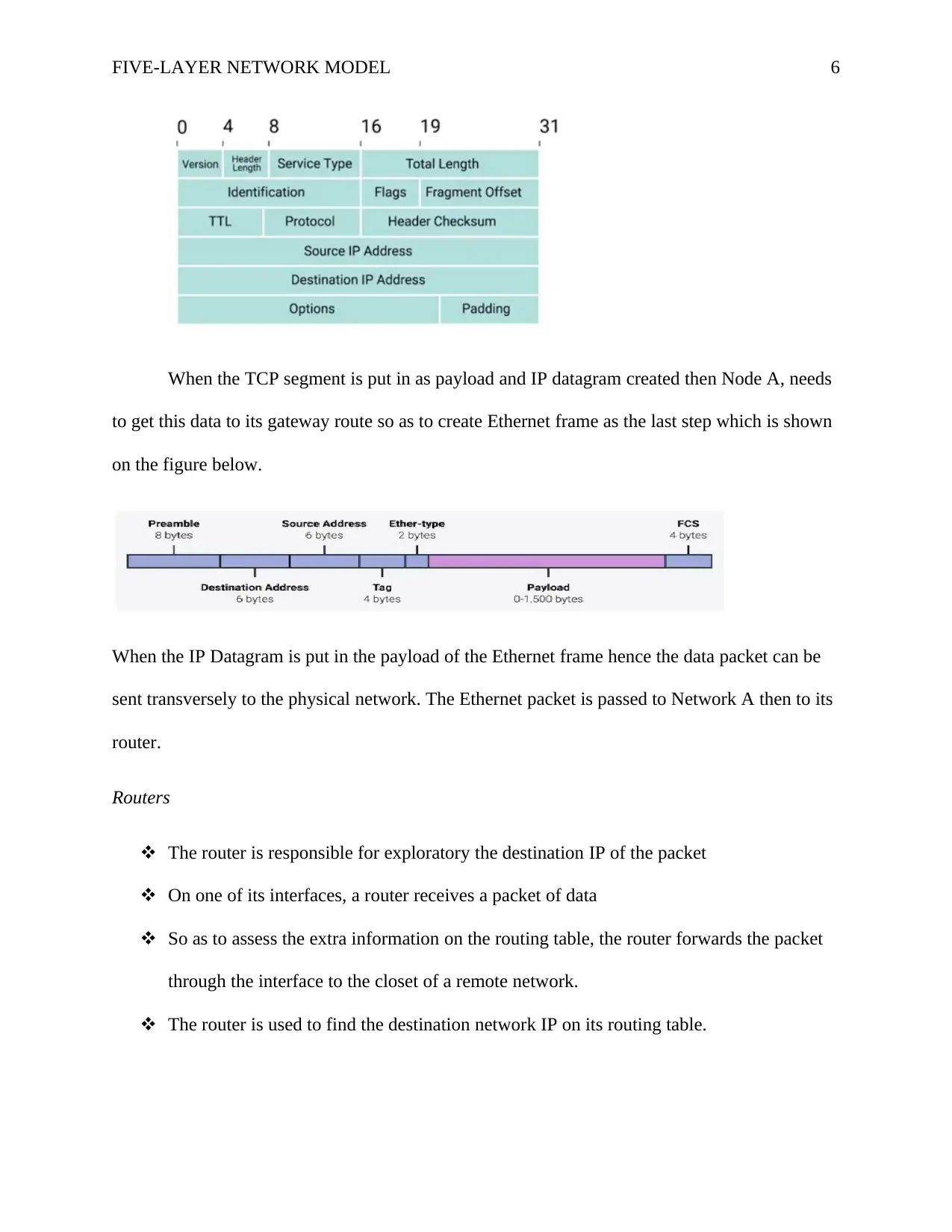
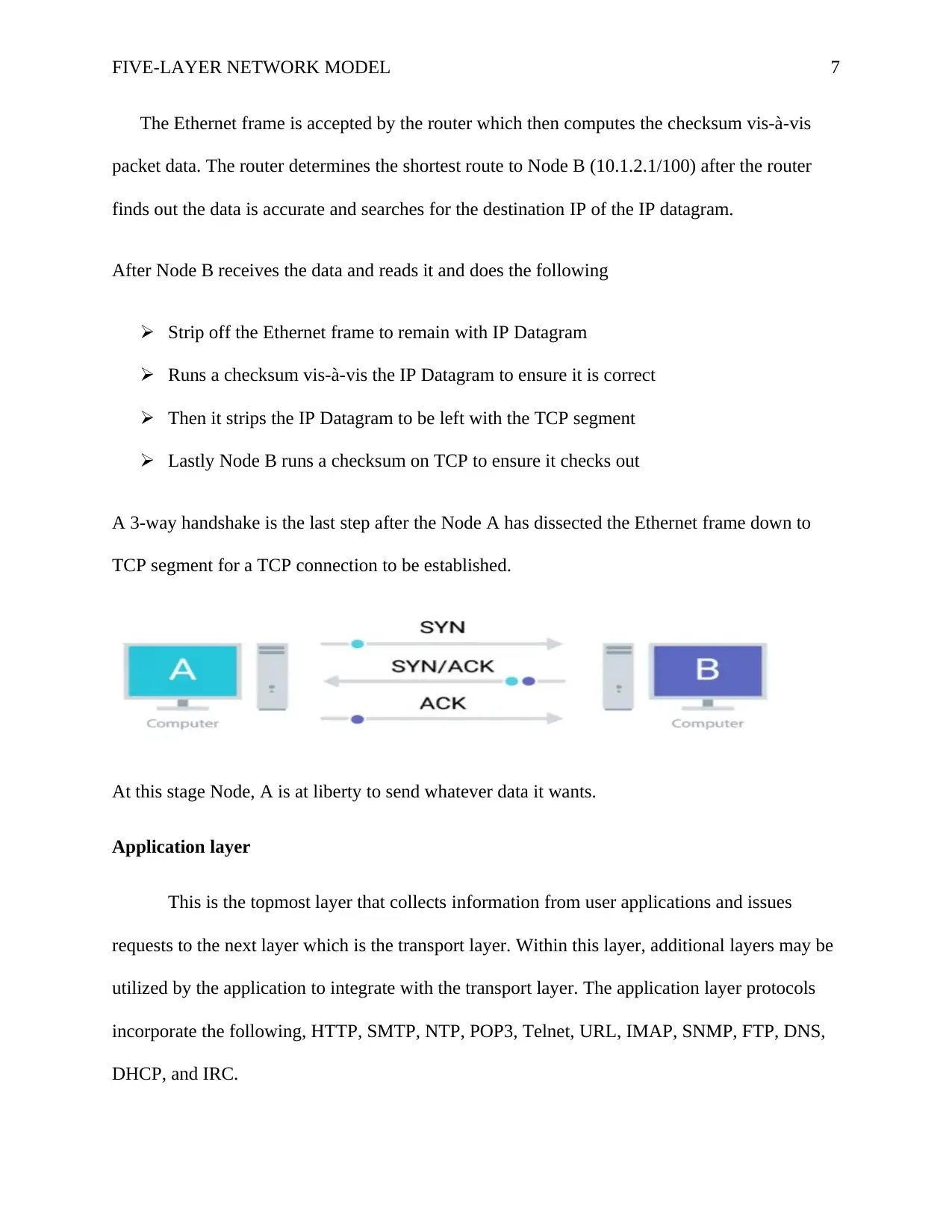
This report provides a detailed explanation of the five-layer network model, crucial for understanding data transmission in networks. It begins by outlining the physical layer, detailing the hardware components like Cat6 cabling, nodes, routers, and switches. The report then moves through the data link layer, focusing on Ethernet protocols and MAC addresses. The transport layer's role in multiplexing and demultiplexing traffic via ports is explained, followed by an analysis of the network layer, including IP addresses and the function of routers in directing data. The report describes how routers find the shortest routes and how data packets traverse networks. Finally, it discusses the application layer, which handles user application requests and interacts with the transport layer using protocols such as HTTP, SMTP, and DNS. The report concludes by highlighting the role of a 3-way handshake in establishing a TCP connection.

Running Header: FIVE-LAYERED NETWORK
Name
Institution
Date
Name
Institution
Date
Paraphrase This Document
Need a fresh take? Get an instant paraphrase of this document with our AI Paraphraser

FIVE-LAYER NETWORK MODEL 2
Several application require to transmit data from point A to Point B in a network. TCP/IP
(Transmission Control Protocol) network gives a system for transmission for this data which
requires rudimentary information from the users to move this data. As a result this paper explores
how this data moves and how each layer on the TCP/IP five-layer network model functions. The
five-layer network model cosists of Application layer, Transport layer, Network layer, Data link
layer and Physical layer.
Physical Layer
The physical layer is responsible for interconnection of all computing devices. This layer is
important as it is the hardware part of the five-layer network model.
Physical layer comprises a number of hardware namely:-
i. Cat6\category 6 known as copper cabling. They are twisted pair protecting the network
from crosstalk.
ii. Node (Desktop Computer) which has an inbuilt network card which has a unique
identifier known as Media control access address (MAC Address).
iii. Router – this is a physical device which function on Network Layer.
iv. Domain controller or Localhost server which is a powerful computer using software to
control network and is a faster node.
v. Switch – this is a physical device which operates at the Data Link layer.
The above-named devices are the one needed to set up a simple network although they are many
devices but for this paper these are the only device needed. All of the devices are connected with
Cat6 cabling utilizing the five-layer network model. The network will comprise a router, two
domain servers, A and B and Node A and Node B which are on a different network.

FIVE-LAYER NETWORK MODEL 3
Using a router the network will be split into two:-
Network A: which comprise of
Server A with an IP address of 192.168.1.0/24
Node A with an IP address of 192.168.1.1/100 which has an Ephemeral socket of 50000
that is 192.168.1.1/50000
Router A with an IP address 192.168.1.0 (Gateway IP)
Network B: which comprise of
Server B with an IP address of 10.1.1.1/24
Node B with an IP address of 10.1.2.1/100 with a socket of 80 that is 10.2.1.1/100
Router B with an IP address of 10.0.0.1 (gateway IP)
The figure below illustrates how the network works
⊘ This is a preview!⊘
Do you want full access?
Subscribe today to unlock all pages.

Trusted by 1+ million students worldwide

FIVE-LAYER NETWORK MODEL 4
When an end user at Node A initiates a request on a host on Network B managed by the
end user on Node B then before the transaction takes place or complete there are several
protocols that takes place. When all devices are plugged like in the picture above and data is
ready to be sent, the next step is how Node A communicate with Node B using the network card.
The communication occurs on the following devices gateway router, switch, Cat6 cabling or
fiber optic cable.
Data Link Layer
This layer is contingent on Ethernet protocol, which comprises how information is
transmitted on either the LAN or WAN. When Node A sends a request on Node B both sides of
network needs Ethernet which has high speed when transferring data. To ensure that the data sent
has both addresses for the source and destination Ethernet utilizes MAC address. When Node A
sends a request to visit a particular resource like a company website on Node B then an outbound
packet is required to be made since the website is not on Network A thus Node A will require to
send any information to its local gateway. Then Node A sends out an Address Resolution
Protocol (ARP) request to find its gateway router which is an ARP request which is a broadcast
of kk.kk.kk.kk.kk.kk. At this point, the router receives the broadcast from Node A and as a
result, it sends Node A MAC address. Thus Node A and the router know each other by MAC
address and IP Address. Hence an outbound packet can be constructed which is an IP Datagram,
the Ethernet frame and TCP Segment encapsulated as one. Ethernet is made up of payload,
source MAC Address, and Destination MAC address.
Paraphrase This Document
Need a fresh take? Get an instant paraphrase of this document with our AI Paraphraser

FIVE-LAYER NETWORK MODEL 5
Transport Layer
The function of this layer is demultiplexing and multiplexing traffic via ports. At the
point Node A initiates a request to visit a company website on Node B, Node A is aware it is
being requested to the web-browser to make an outbound TCP connection thus requiring an
outbound TCP port. The operating system of Node A recognizes the TCP connection construct
an Ephemeral link of 60000 which is the socket number and links the web server through this
port.
When a short-lived Ephemeral socket is opened up for the web-browser by the operating
system the Node A begin to put up together the TCP segment. Hence the TCP segment is passed
to the next layer which is the network layer.
Network Layer
This layer enables various networks to communicate through routers and assigning IP
addresses. On this layer, the IP Datagram is created. An IP address is made up of a 32-bit
number which comprises a Host ID and a Network ID. Using DHCP an IP address is assigned to
every device on the network. After the creation of both the IP Datagram and TCP segment by
Network A by inputting the data that is needed which is demonstrated by the figure below.

FIVE-LAYER NETWORK MODEL 6
When the TCP segment is put in as payload and IP datagram created then Node A, needs
to get this data to its gateway route so as to create Ethernet frame as the last step which is shown
on the figure below.
When the IP Datagram is put in the payload of the Ethernet frame hence the data packet can be
sent transversely to the physical network. The Ethernet packet is passed to Network A then to its
router.
Routers
The router is responsible for exploratory the destination IP of the packet
On one of its interfaces, a router receives a packet of data
So as to assess the extra information on the routing table, the router forwards the packet
through the interface to the closet of a remote network.
The router is used to find the destination network IP on its routing table.
⊘ This is a preview!⊘
Do you want full access?
Subscribe today to unlock all pages.

Trusted by 1+ million students worldwide

FIVE-LAYER NETWORK MODEL 7
The Ethernet frame is accepted by the router which then computes the checksum vis-à-vis
packet data. The router determines the shortest route to Node B (10.1.2.1/100) after the router
finds out the data is accurate and searches for the destination IP of the IP datagram.
After Node B receives the data and reads it and does the following
Strip off the Ethernet frame to remain with IP Datagram
Runs a checksum vis-à-vis the IP Datagram to ensure it is correct
Then it strips the IP Datagram to be left with the TCP segment
Lastly Node B runs a checksum on TCP to ensure it checks out
A 3-way handshake is the last step after the Node A has dissected the Ethernet frame down to
TCP segment for a TCP connection to be established.
At this stage Node, A is at liberty to send whatever data it wants.
Application layer
This is the topmost layer that collects information from user applications and issues
requests to the next layer which is the transport layer. Within this layer, additional layers may be
utilized by the application to integrate with the transport layer. The application layer protocols
incorporate the following, HTTP, SMTP, NTP, POP3, Telnet, URL, IMAP, SNMP, FTP, DNS,
DHCP, and IRC.
Paraphrase This Document
Need a fresh take? Get an instant paraphrase of this document with our AI Paraphraser

FIVE-LAYER NETWORK MODEL 8
1 out of 8
Related Documents

Your All-in-One AI-Powered Toolkit for Academic Success.
+13062052269
info@desklib.com
Available 24*7 on WhatsApp / Email
Unlock your academic potential
Copyright © 2020–2025 A2Z Services. All Rights Reserved. Developed and managed by ZUCOL.