Engineering Materials Practical 2: Flexural Testing Lab Report
VerifiedAdded on 2023/01/19
|18
|2847
|21
Report
AI Summary
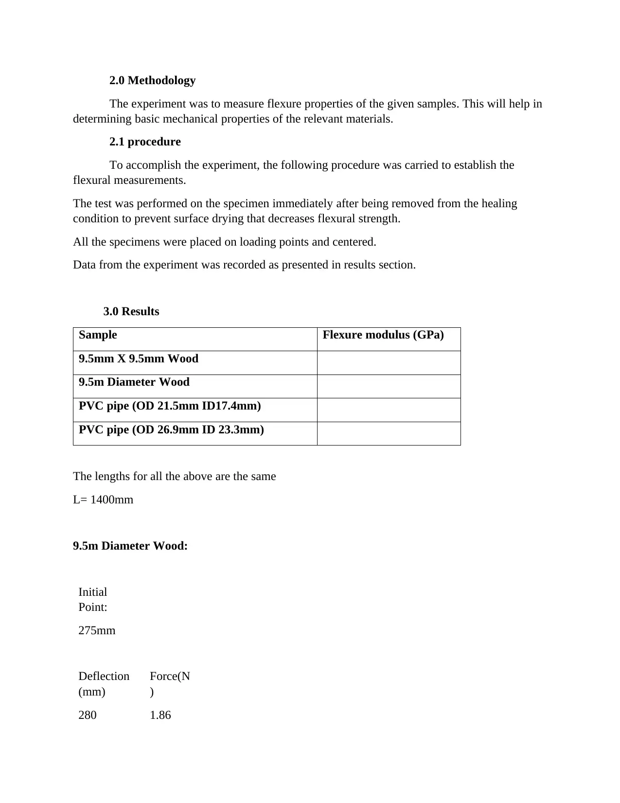
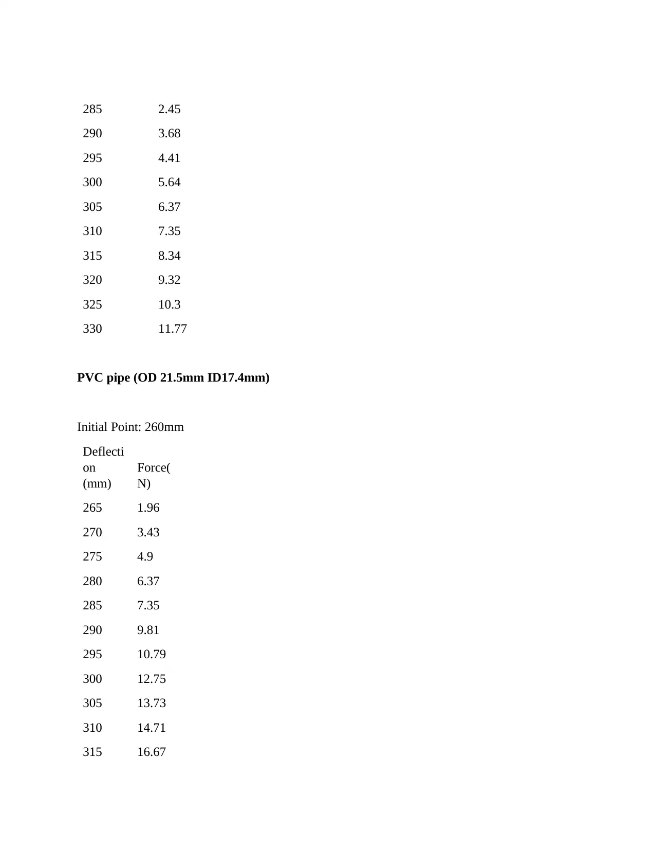
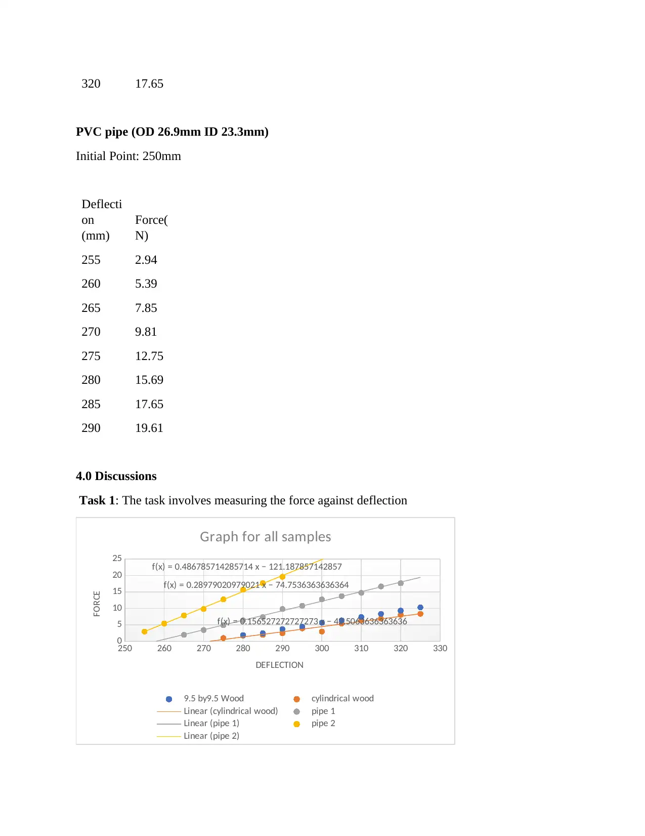
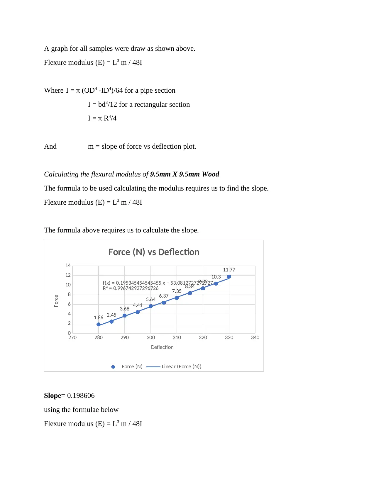
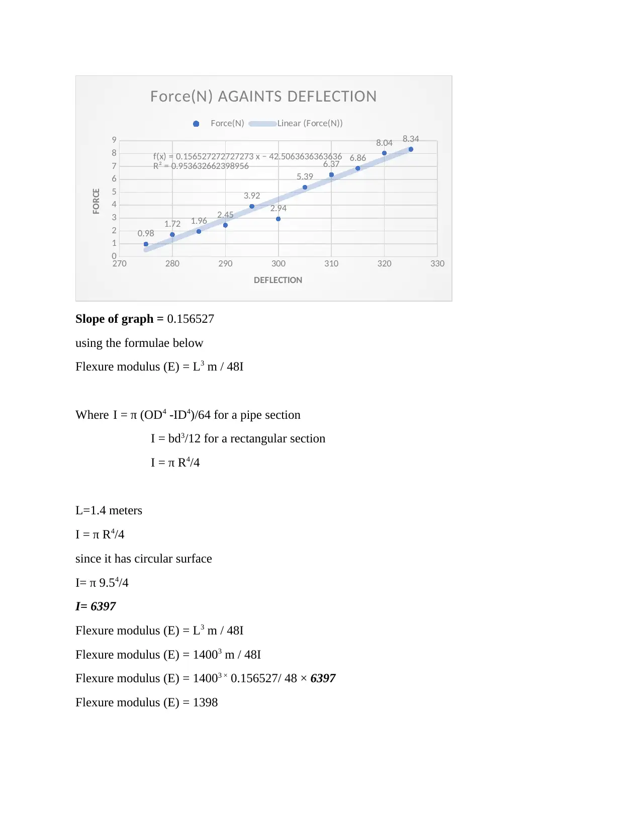
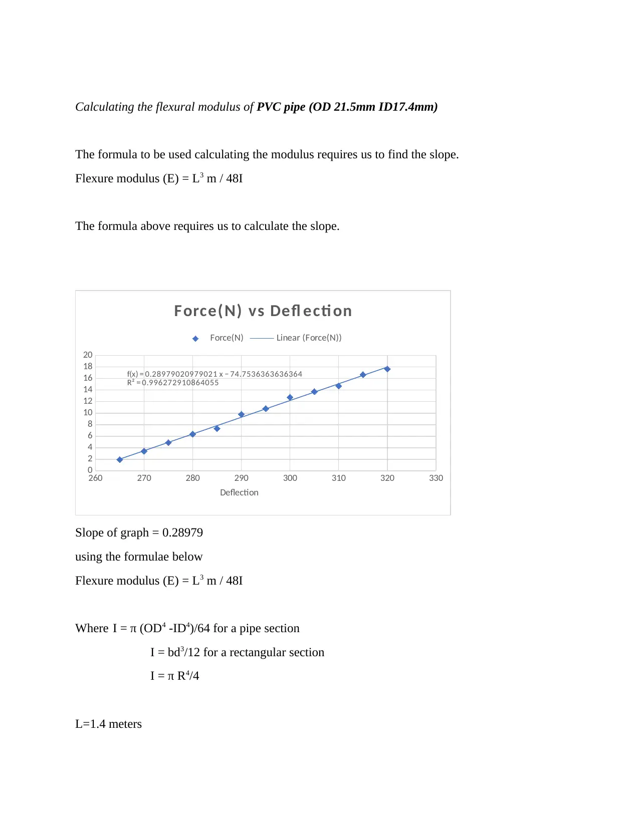
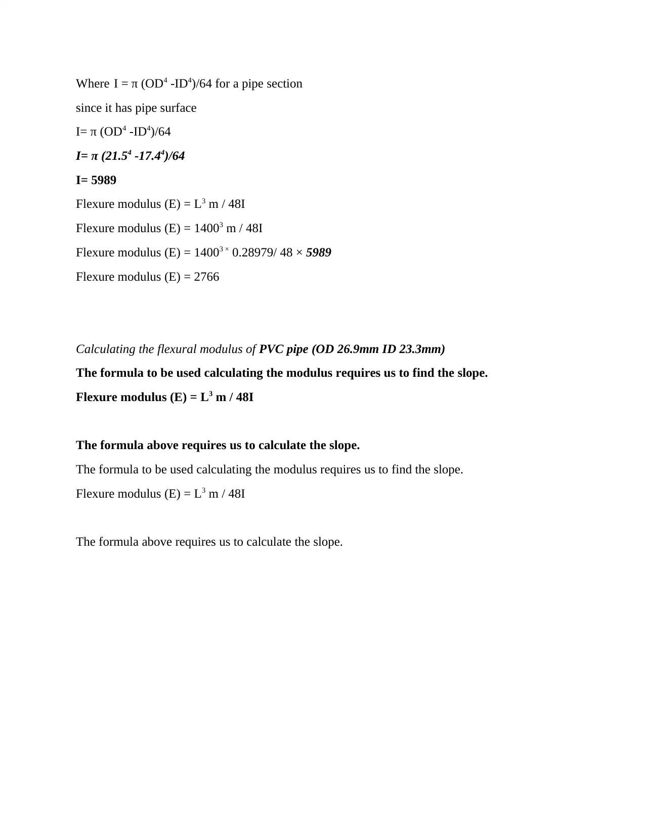
This report details a flexural testing experiment conducted on various materials, including wood and PVC pipes, to determine their flexural properties. The methodology involved applying loads to the samples and measuring the resulting deflections. The results section presents the collected data and includes calculations for flexural modulus. The discussion section analyzes the force-deflection graphs and calculates flexural modulus for each sample. Further calculations determine deflections for different scenarios, such as a wood plank and a PVC pipe under specific loads. Additionally, the report addresses problem-solving tasks involving beam design, load capacity calculations, and material selection for a gantry crane, utilizing stress-strain curves and safety factors to ensure structural integrity.

Flexural Testing Lab Report
Student name
Student level or class
Lecturers name
School name
School location
Date of submission
Student name
Student level or class
Lecturers name
School name
School location
Date of submission
Secure Best Marks with AI Grader
Need help grading? Try our AI Grader for instant feedback on your assignments.

1.0 Introduction
Flexural test is used to assess a material's flexibility or bending properties. Often referred
to as an anterior beam test, it involves putting a data set between two points or supports and
initiating a load using a third or two points calling 3-Point Bend and 4-Point Bend tests
respectively (Aametektest.com, 2019). On the iterative load applied, the maximum stress and
strain are calculated. Outcomes are displayed in a visual format with tabular results including
flexural strength (for fragmented specimens) and produce strength (samples not fracturing).
Plastics, composites, metals, ceramics and wood are typical components tested
Usually, flexure tests are used to establish a material's flexural module or flexural
strength. The specimen which is to be tested is laid on two supports, then force is applied. (upper
load span) this force is applied until the specimen deforms. ("flexural strength test of concrete
(IS:516-1959 ...). The most extreme recorded power is that specific example's flexural quality.
The most noteworthy conceivable recorded power is that specific example's flexural quality. The
most utilized tests are thre and four-point tests ("Flexural Test - Test Resources"). A three-point
twist test contains the informational index put vertically at two points and the push connected
through a solitary point to both the highest point of the example with the goal that the example is
bowed as a "V." A four-point twist test is equivalent to how it is connected by means of two
rather than the power connected through a solitary point at the top so the example associations
contact at four different focuses and is tilted more as a "U."
Estimating flexural strength and flexural modulus is the most well-known objective of a
flexure test. Flexural quality on either the disfigurement or pressure side of the specimen is
characterized as the most extreme weight on the peripheral material. Considering the incline of
the pressure versus strain redirection bend, the flexural module is determined. These two
qualities can be utilized to survey the capacity to withstand flexure or twisting powers of the
example materials ("Flexural Fatigue - Pavement Interactive) (Behera, 2012).

2.0 Methodology
The experiment was to measure flexure properties of the given samples. This will help in
determining basic mechanical properties of the relevant materials.
2.1 procedure
To accomplish the experiment, the following procedure was carried to establish the
flexural measurements.
The test was performed on the specimen immediately after being removed from the healing
condition to prevent surface drying that decreases flexural strength.
All the specimens were placed on loading points and centered.
Data from the experiment was recorded as presented in results section.
3.0 Results
Sample Flexure modulus (GPa)
9.5mm X 9.5mm Wood
9.5m Diameter Wood
PVC pipe (OD 21.5mm ID17.4mm)
PVC pipe (OD 26.9mm ID 23.3mm)
The lengths for all the above are the same
L= 1400mm
9.5m Diameter Wood:
Initial
Point:
275mm
Deflection
(mm)
Force(N
)
280 1.86

285 2.45
290 3.68
295 4.41
300 5.64
305 6.37
310 7.35
315 8.34
320 9.32
325 10.3
330 11.77
PVC pipe (OD 21.5mm ID17.4mm)
Initial Point: 260mm
Deflecti
on
(mm)
Force(
N)
265 1.96
270 3.43
275 4.9
280 6.37
285 7.35
290 9.81
295 10.79
300 12.75
305 13.73
310 14.71
315 16.67
290 3.68
295 4.41
300 5.64
305 6.37
310 7.35
315 8.34
320 9.32
325 10.3
330 11.77
PVC pipe (OD 21.5mm ID17.4mm)
Initial Point: 260mm
Deflecti
on
(mm)
Force(
N)
265 1.96
270 3.43
275 4.9
280 6.37
285 7.35
290 9.81
295 10.79
300 12.75
305 13.73
310 14.71
315 16.67
Secure Best Marks with AI Grader
Need help grading? Try our AI Grader for instant feedback on your assignments.

320 17.65
PVC pipe (OD 26.9mm ID 23.3mm)
Initial Point: 250mm
Deflecti
on
(mm)
Force(
N)
255 2.94
260 5.39
265 7.85
270 9.81
275 12.75
280 15.69
285 17.65
290 19.61
4.0 Discussions
Task 1: The task involves measuring the force against deflection
250 260 270 280 290 300 310 320 330
0
5
10
15
20
25 f(x) = 0.486785714285714 x − 121.187857142857
f(x) = 0.28979020979021 x − 74.7536363636364
f(x) = 0.156527272727273 x − 42.5063636363636
Graph for all samples
9.5 by9.5 Wood cylindrical wood
Linear (cylindrical wood) pipe 1
Linear (pipe 1) pipe 2
Linear (pipe 2)
DEFLECTION
FORCE

A graph for all samples were draw as shown above.
Flexure modulus (E) = L3 m / 48I
Where I = π (OD4 -ID4)/64 for a pipe section
I = bd3/12 for a rectangular section
I = π R4/4
And m = slope of force vs deflection plot.
Calculating the flexural modulus of 9.5mm X 9.5mm Wood
The formula to be used calculating the modulus requires us to find the slope.
Flexure modulus (E) = L3 m / 48I
The formula above requires us to calculate the slope.
270 280 290 300 310 320 330 340
0
2
4
6
8
10
12
14
1.86 2.45
3.68 4.41
5.64 6.37 7.35 8.34 9.32 10.3
11.77
f(x) = 0.195345454545455 x − 53.0812727272727
R² = 0.996742927296726
Force (N) vs Deflection
Force (N) Linear (Force (N))
Deflection
Force
Slope= 0.198606
using the formulae below
Flexure modulus (E) = L3 m / 48I

Where I = π (OD4 -ID4)/64 for a pipe section
I = bd3/12 for a rectangular section
I = π R4/4
L=1.4 meters
I= bd3/12 since it has rectangular surface
I= 9.5mm X 9.5 3mm3 /12
I= 678.76 mm4 (Mathalino.com, 2019).
Flexure modulus (E) = L3 m / 48I
Flexure modulus (E) = 14003 m / 48I
Flexure modulus (E) = 14003 × 0.198606 / 48 × 678.76
Flexure modulus (E) = 16727
Calculating the flexural modulus of 9.5m Diameter Wood
The formula to be used calculating the modulus requires us to find the slope.
Flexure modulus (E) = L3 m / 48I
The formula above requires us to calculate the slope.
Paraphrase This Document
Need a fresh take? Get an instant paraphrase of this document with our AI Paraphraser

270 280 290 300 310 320 330
0
1
2
3
4
5
6
7
8
9
0.98
1.72 1.96 2.45
3.92
2.94
5.39
6.37 6.86
8.04 8.34
f(x) = 0.156527272727273 x − 42.5063636363636
R² = 0.953632662398956
Force(N) AGAINTS DEFLECTION
Force(N) Linear (Force(N))
DEFLECTION
FORCE
Slope of graph = 0.156527
using the formulae below
Flexure modulus (E) = L3 m / 48I
Where I = π (OD4 -ID4)/64 for a pipe section
I = bd3/12 for a rectangular section
I = π R4/4
L=1.4 meters
I = π R4/4
since it has circular surface
I= π 9.54/4
I= 6397
Flexure modulus (E) = L3 m / 48I
Flexure modulus (E) = 14003 m / 48I
Flexure modulus (E) = 14003 × 0.156527/ 48 × 6397
Flexure modulus (E) = 1398

Calculating the flexural modulus of PVC pipe (OD 21.5mm ID17.4mm)
The formula to be used calculating the modulus requires us to find the slope.
Flexure modulus (E) = L3 m / 48I
The formula above requires us to calculate the slope.
260 270 280 290 300 310 320 330
0
2
4
6
8
10
12
14
16
18
20
f(x) = 0.28979020979021 x − 74.7536363636364
R² = 0.996272910864055
Force(N) vs Defl ecti on
Force(N) Linear (Force(N))
Deflection
Slope of graph = 0.28979
using the formulae below
Flexure modulus (E) = L3 m / 48I
Where I = π (OD4 -ID4)/64 for a pipe section
I = bd3/12 for a rectangular section
I = π R4/4
L=1.4 meters

Where I = π (OD4 -ID4)/64 for a pipe section
since it has pipe surface
I= π (OD4 -ID4)/64
I= π (21.54 -17.44)/64
I= 5989
Flexure modulus (E) = L3 m / 48I
Flexure modulus (E) = 14003 m / 48I
Flexure modulus (E) = 14003 × 0.28979/ 48 × 5989
Flexure modulus (E) = 2766
Calculating the flexural modulus of PVC pipe (OD 26.9mm ID 23.3mm)
The formula to be used calculating the modulus requires us to find the slope.
Flexure modulus (E) = L3 m / 48I
The formula above requires us to calculate the slope.
The formula to be used calculating the modulus requires us to find the slope.
Flexure modulus (E) = L3 m / 48I
The formula above requires us to calculate the slope.
Secure Best Marks with AI Grader
Need help grading? Try our AI Grader for instant feedback on your assignments.

250 255 260 265 270 275 280 285 290 295
0
5
10
15
20
25
f(x) = 0.486785714285714 x − 121.187857142857
R² = 0.997285857015173
Force(N) VS DEFLECTION
Force(N) Linear (Force(N))
DEFLECTION
FORCE
Slope of graph = 0.486786
using the formulae below
Flexure modulus (E) = L3 m / 48I
Where I = π (OD4 -ID4)/64 for a pipe section
I = bd3/12 for a rectangular section
I = π R4/4
L=1.4 meters
Where I = π (OD4 -ID4)/64 for a pipe section
since it has pipe surface
I= π (OD4 -ID4)/64
I= π (26.94 -23.34)/64
I= 11235
Flexure modulus (E) = L3 m / 48I
Flexure modulus (E) = 14003 m / 48I
Flexure modulus (E) = 14003 × 0.486786/ 48 × 11235

Flexure modulus (E) = 2476
The table below will be filled as shown below.
Sample Flexure modulus (GA)
9.5mm X 9.5mm Wood 1398
9.5m Diameter Wood 16727
PVC pipe (OD 21.5mm ID17.4mm) 2766
PVC pipe (OD 26.9mm ID 23.3mm) 2476
Task 2: Using the average values for flexural modulus of wood and PVC you calculated above,
calculate the deflections for the following samples: Show your working
10mm x 100mm plank at a Load of 150N and a span of 1m.
From the Equations
Flexure modulus (E) = L3 m / 48I
L= 1METRE
I = bd3/12 for a rectangular section
I= 1000×10003 /12
I=8333333.3mm4
1398 =10003 m/48 × 8333333.3
M= 559.5
From the equation,
y=559x- intercept
y=150
150= 559x-53
X= 0.363mm

PVC pipe OD 100mm, ID 95mm at a load of 1000N and a span of 1m
From the Equations
Flexure modulus (E) = L3 m / 48I
L= 1METRE
I = π (OD4 -ID4)/64
I= π (1004 -954)/64
I=910540mm4
2766 =10003 m/48 × 910540
M= 120
From the equation,
y=120x- intercept
y=1000
1000= 120x-74
X= 8mm
Section B – Problem solving
Task 3: a beam with the dimensions, 2m long with a cross-section of 10mm x 50mm, material is
wood. The properties are as listed in table below.
Table 1. Properties of wood beam.
Property Value
y 50MPa
TS 70MPa
E 25GPa
Maximum load which the beam can support is 10 kilograms.
Figure 1. Schematic of wood beam supporting a 10kg load and end view of the beam
Paraphrase This Document
Need a fresh take? Get an instant paraphrase of this document with our AI Paraphraser

Using a safety factor of 2, calculate the span between the rollers to which the load is
supported and still safe.
The maximum load is 10kN, to ensure safety, we consider the safety factor given as 2.
Hence, maximum design load is 20kN.
The second moment of area for the beam will be calculated as follows,
I = bd3/12 for a rectangular section
I=50 × 103 /12
I=4166mm4
(Ijaed, 2014).
Where p=20kN
L=distance between the supports
To find M, we use the equation below
M= y × I/y
M= 0.0050 × 4166mm4 / 5mm
M=4.1660
L=4.1660 × 4/20
L=0.8m
What is the maximum deflection at this distance?
The Equation below will be used to calculate maximum bending
(Mandal, Tinjum, Gokce & Edil, 2015)
The initials are as defined below,
E is the young’s modulus,
E=25GPa
I= moment of inertia
L= length of the wood beam
X=safety distance
W= 10kN load used in the specimen
y= 10 x 0.8
48 x 25 x 4166 [3x 22 -4x0.82 ]
y=0.0151m

(Sunainah and Sutantra, 2018)
Task 4: A gantry crane must take a maximum load of 1000kg, as below in Figure 2. A steel wire
with a 4:1 pulley system is used to support the load. Steel wire can be purchased in 2.5mm,
3mm, 4.5mm, 6.25mm, 8mm and 12.7mm diameters.
Figure 2. diagram showing the gantry crane which can support maximum load of 1000
kilograms.
0 0.02 0.04 0.06 0.08 0.1 0.12 0.14 0.16 0.18
0
50
100
150
200
250
300
350
400
450
Strain
Stress (MPa)
Figure 3. Stress vs strain graph for Steel wire.
Using the stress – strain curve below (Figure 3), determine which diameter steel should be
used. Use a safety factor of 3.
Total design weight considering the safety factor is given as
W=1000 x 3kg
W=30000N
Stress = F/A
Maximum stress =400
400=30000/A

A= 75mm2
A = π R2
R2 = 75/ π
D = 9.7
D = 12.7mm
If the length of the wire is 2m, how much does the wire stretch? (Elastic modulus = 180
GPa)
Stress = 400mpa
From equation below
(Mandal, Tinjum, Gokce & Edil, 2015)
E=180
Stress =400
Strain =400/180000
Strain= 0.0022
Strain= dL
L
L=2m
dL= 0.0044m
Task 5:
Span of crane in task above is 3 meters.
The properties of the rod which is to be used in calculating the beam was as provided in table 2
below.
Using a safety factor of 2, calculate the diameter of the rod that can be used in this case.
Table 2. Properties of structural steel
Property Value
y 220MPa
TS 400MPa
E 200GPa
From the safety factor, maximum design load is calculated as follows,
P=1000kg x 2
W=20000N
Stress =220mpa
Force =20000N
But stress = force/area
Area =20000/ 220
Cross section = 912
Secure Best Marks with AI Grader
Need help grading? Try our AI Grader for instant feedback on your assignments.

A = π R2
R2 = 91/ π
D = 10.76
D = 0.11m
Task 6: From the dimensions above,
The maximum deflection of top beam was calculated as shown below.
maximum deflection given by the formulae below
I= π R4 /64
y= 5 x 20000 x 81+8 x 2000 x 27
384 x 200 x 718618
y=0.0000225m
References
Behera, A. (2012). Electric Overhead Travelling Crane Model. Saarbrücken: LAP LAMBERT
Academic Publishing.
European, U. (2019). Eurocode 3 - Design of steel structures - Part 6: Crane supporting
structures. 3rd ed. European union: European Standard.
Ijaed (2014). Design, Analysis and Optimization of Overhead Crane Girder. International
Journal of Advance Engineering and Research Development, 1(06).
Lassila, L.V., Tanner, J., Le Bell, A.M., Narva, K. and Vallittu, P.K., 2004. Flexural properties
of fiber reinforced root canal posts. Dental Materials, 20(1), pp.29-36.
Mathalino.com. (2019). Moving Loads | Strength of Materials Review . [online]
Available at: https://www.mathalino.com/reviewer/mechanics-and-strength-of-
materials/moving-loads [Accessed 29 Mar. 2019].
Qu, X., Xu, G., Fan, X. and Bi, X. (2014). Intelligent optimization methods for the design of an
overhead travelling crane. Chinese Journal of Mechanical Engineering, 28(1), pp.187-196.

Sunainah, A. and Sutantra, I. (2018). Analisis dan Redesign Kekuatan Struktur pada Girder
Overhead Crane 6.3 Ton. Jurnal Teknik ITS, 7(1).
Tian, G., Zhang, S. and Sun, S. (2012). The Optimization Design of Overhead Traveling Crane's
Box Girder. Advanced Materials Research, 538-541, pp.2850-2855.
Yousif, B.F., Shalwan, A., Chin, C.W. and Ming, K.C., 2012. Flexural properties of treated and
untreated kenaf/epoxy composites. Materials & Design, 40, pp.378-385.
1 out of 18
Related Documents

Your All-in-One AI-Powered Toolkit for Academic Success.
+13062052269
info@desklib.com
Available 24*7 on WhatsApp / Email
Unlock your academic potential
© 2024 | Zucol Services PVT LTD | All rights reserved.