Advanced Flow Modelling 49312: Flow Analysis Over Cylinders

Verified

Added on  2023/04/22

|19
|2851
|196
Report
AI Summary
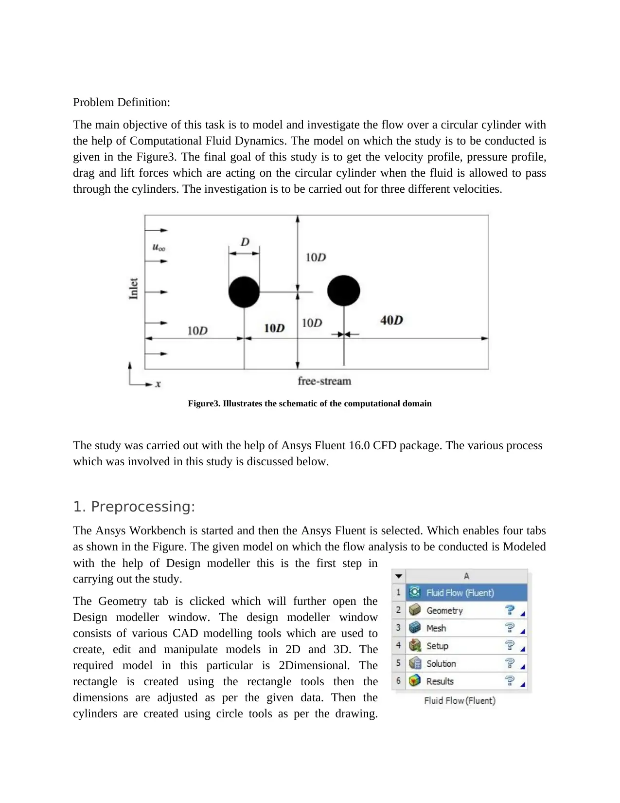
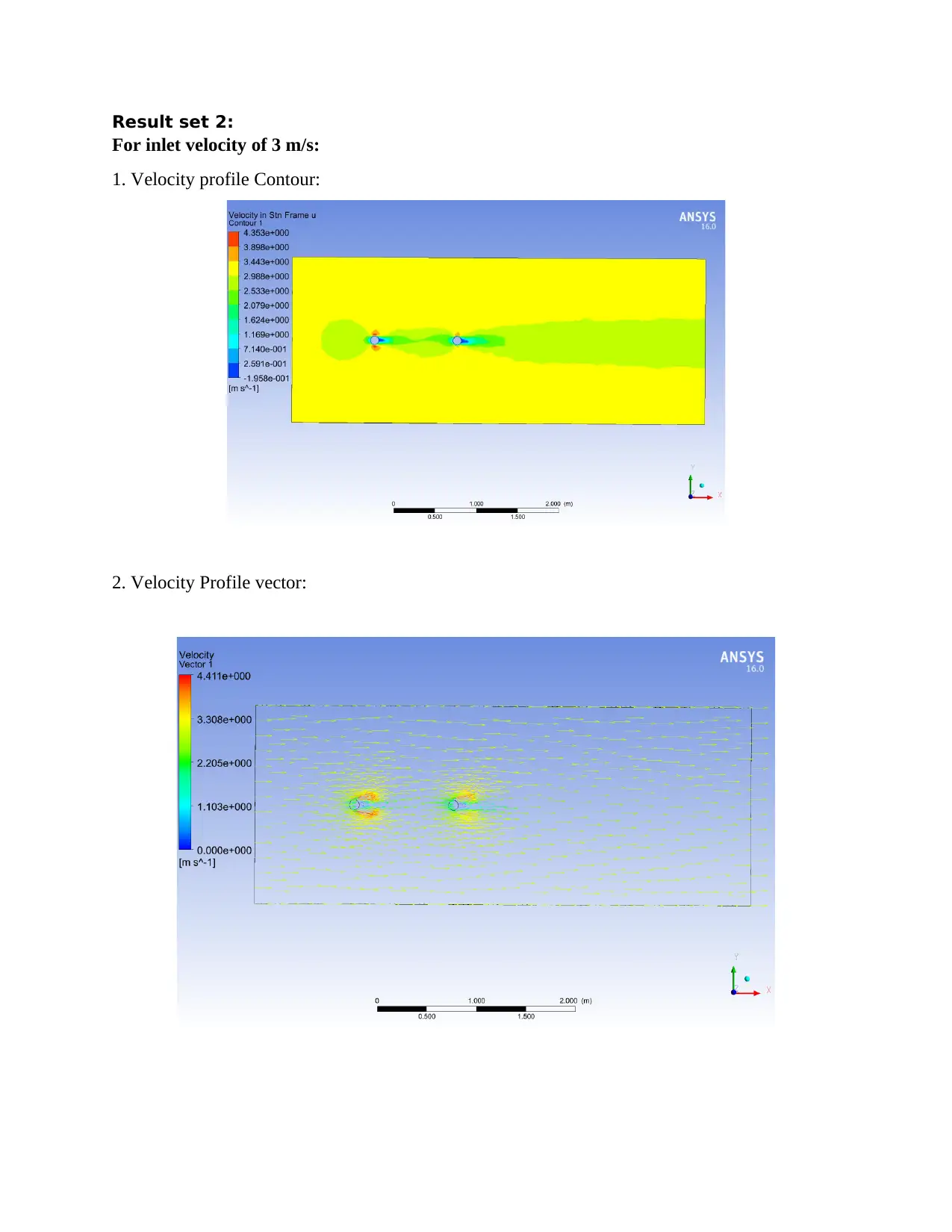
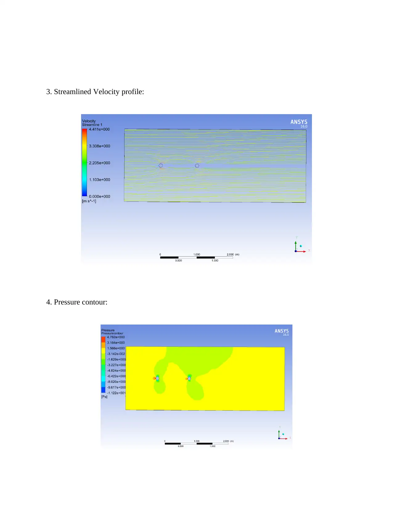
This report presents a Computational Fluid Dynamics (CFD) analysis of flow over a pair of cylinders using Ansys Fluent. The study encompasses three key phases: preprocessing (CAD model creation and meshing), solving (boundary condition setup, fluid property definition, and simulation execution), and post-processing (result interpretation). The analysis investigates velocity profiles, pressure contours, drag forces, and lift forces for three different inlet air velocities (1 m/s, 3 m/s, and 5 m/s). The results indicate that pressure and velocity along the cylinder walls increase proportionally with the inlet air velocity. The report concludes with a comparison of lift and drag forces for each velocity condition, demonstrating the impact of flow velocity on cylinder dynamics. Desklib provides access to this and other solved assignments to aid students in their studies.
Document Page
Advanced Flow Modelling
Contents
Introduction:....................................................................................................................................................................1
Analysis:..........................................................................................................................................................................3
1. Preprocessing:........................................................................................................................................................4
2. Solving.....................................................................................................................................................................5
3. Post-processing.......................................................................................................................................................6
Results:............................................................................................................................................................................6
Conclusion:....................................................................................................................................................................18
References:...................................................................................................................................................................19
tabler-icon-diamond-filled.svg

Secure Best Marks with AI Grader

Need help grading? Try our AI Grader for instant feedback on your assignments.
Document Page
Introduction:
Introduction to CFD:
CFD-Computational Fluid Dynamics is the study of the systems which includes Flow of fluid,
transfer of heat, chemical reactions, etc. with the help of computer-aided simulation. In general,
the problems which involve the fluid flow, heat transfer, chemical reactions, etc. are being solved
with the help of the Computers which are pre-installed with a proper CFD software Package.
(Olsen, J.E. and Johansen, S.T., 2015)
The software package consists of powerful tools in order to simulate, Analyze, Compute, and
Animate and execute the various input data’s. Some of the most utilized CFD package as of now
are Ansys Fluent, Solidworks simulate, Star CCM+, COMSOL Multiphysics, Ansys CFX,
Autodesk Simulation, Altair Acusolve, Xflow CFD, Simscale. These are the most used CFD
software packages as of now. The CFD packages greatly improve productivity, produces
efficient algorithms to solve a problem, accuracy in results, quick and accurate computation, etc.
Figure1. Illustrates the Flow Analysis done on a Centrifugal Pump with the help of a CFD software Package.
The computational fluid Dynamics works on the three basic fundamental principles they are:
Mass conservation principle, the second law of Newton or Naiver-Strokes equation, Energy
conservation principle or Bernoulli’s Equation. The CFD consists of many applications in
various fields such as Aeronautics in which the CFD is utilized to conduct a flow analysis on the
aerodynamics of aircrafts the various forces such as lift, drag, the coefficient of drag, etc. will be
calculated using the package. (D’Alessandro, V., et.al 2016)
The Automotive industries utilize the CFD package in order to conduct flow analysis on both the
internal and external parts such as flow analysis over the surface of an automobile, flow analysis
inside the automotive components such as a compressor, turbocharger, engine manifolds, etc. In
thermal power plants, it is utilized to conduct analysis on the turbines and other machines, heat
Document Page
flow analysis etc. In HVAC the CFD plays a major role as the field is purely on the basis of the
flow of heat. Including this field, the CFD also has many wide varieties of applications.
In this study, the CFD package will be used to conduct a flow analysis over a couple of cylinders
which are confined in a particular space. The various steps involved in the computation will be
explained in further topics. ( Benitz, M.A., et.al 2016)
Figure2. Illustrates the velocity profile of air which is a result of flow analysis using CFD over a Motorcycle.
Analysis:
The task that is given in this module is to conduct a Flow Analysis over a couple of cylinders.
The Analysis will be carried out with the help of Ansys Fluent CFD package. The analysis is
separated into three parts such as:
1. Pre-processing
2. Solving
3. Post processing
The preprocessing phase involves the process of creation of a CAD model on which the Analysis
will be carried out and Meshing the created mode. The solving part includes the process of
setting up the boundary conditions, inlet and outlet conditions, fluid properties, analysis type,
computational requirements, etc. In this phase, the problem will be solved completely after
providing proper data. The final part is the post-processing in which the computed results will be
interpreted with the help of Ansys CFD post window. (Eswaran, M., et.al 2016)
Document Page
Problem Definition:
The main objective of this task is to model and investigate the flow over a circular cylinder with
the help of Computational Fluid Dynamics. The model on which the study is to be conducted is
given in the Figure3. The final goal of this study is to get the velocity profile, pressure profile,
drag and lift forces which are acting on the circular cylinder when the fluid is allowed to pass
through the cylinders. The investigation is to be carried out for three different velocities.
Figure3. Illustrates the schematic of the computational domain
The study was carried out with the help of Ansys Fluent 16.0 CFD package. The various process
which was involved in this study is discussed below.
1. Preprocessing:
The Ansys Workbench is started and then the Ansys Fluent is selected. Which enables four tabs
as shown in the Figure. The given model on which the flow analysis to be conducted is Modeled
with the help of Design modeller this is the first step in
carrying out the study.
The Geometry tab is clicked which will further open the
Design modeller window. The design modeller window
consists of various CAD modelling tools which are used to
create, edit and manipulate models in 2D and 3D. The
required model in this particular is 2Dimensional. The
rectangle is created using the rectangle tools then the
dimensions are adjusted as per the given data. Then the
cylinders are created using circle tools as per the drawing.
tabler-icon-diamond-filled.svg

Secure Best Marks with AI Grader

Need help grading? Try our AI Grader for instant feedback on your assignments.
Document Page
Finally, the surface plane is created and the particle inside the rectangular plate is assigned as
Fluid.
The second step is to create a Mesh meshing is the process of creating finite elements, which
means the whole Geometry is discretized. Discretization is the process of breaking down a
geometry into individual elements which are connected together by nodes. The points at which
the element join with each other are known as nodes. The mesh density, sizing and the other
options are provided on the mesh window then the mesh is generated. The mesh is investigated
for any error and then the final meshed model is updated.
Figure4. Illustrates the meshed model.
2. Solving
The solving phase is the one in which all the necessary inlet, outlet and boundary conditions will
be set and the entire study will be solved. The boundary conditions for the inlet, outlet, wall and
the cylinders are all assigned. The boundary type assigned for the various parts is shown below.
Domain Boundaries
Geometr
y
Boundary - cylinders
Typ
e
WALL
Boundary - inlet
Typ
e
VELOCITY-INLET
Boundary - outlet
Typ
e
PRESSURE-OUTLET
Boundary - symmetry 1
Typ
e
SYMMETRY
Boundary - symmetry 2
Typ
e
SYMMETRY
Boundary - wall
Document Page
Typ
e
WALL
Then the type of fluid was selected as air. The properties of the selected fluid are entered at the
materials tab in the setup window. The materials tab is shown in the figure5. Which is given
below.
Figure5. Illustrated the materials window.
Then the inlet and outlet conditions are selected for the study in the Boundary conditions tab.
The inlet air density is given as 1.2 Kg/m3 and the velocity is given as 1 m/s for the first
condition, for the second and third Conditions the velocities of the inlet air are given as 3 m/s
and 5 m/s. Then the solution method and the solution initialization is selected. Finally, the
number of iterations and the steps per iterations are set. Then the calculate button is pressed
which will completely solve the problem, all the computations will be done. (Kumar, A., et.al
2015)
3. Post processing
The post-processing is the phase in which the computed results will be interpreted. The Ansys
CFD post will be opened and then the following results for the study are interpreted.
Document Page
Results:
1. Velocity profile Contour
2. Velocity Profile vector
3. Streamlined Velocity profile
4. Pressure contour.
5. Drag force.
6. Lift force.
These six results will be interpreted for the three different inlet conditions as:
Result set 1:
For inlet velocity of 1m/s:
1. Velocity profile Contour:
tabler-icon-diamond-filled.svg

Paraphrase This Document

Need a fresh take? Get an instant paraphrase of this document with our AI Paraphraser
Document Page
2. Velocity Profile vector:
.
3. Streamlined Velocity profile:
Document Page
4. Pressure contour:
5. Velocity graph:
Document Page
6. Drag force:
The drag force is interpreted from the solution as:
Drag force:
Zone Pressure Viscous Total Pressure Viscous Total
wall 5.7129152e-18 0 5.7129152e-18 9.521525e-18 0 9.521525e-18
cylinders 0.045477328 0.0013633114 0.046840639 0.075795543 0.0022721856 0.078067729
------------------------- --------------- --------------- --------------- --------------- --------------- ---------------
Net 0.045477328 0.0013633114 0.046840639 0.075795543 0.0022721856 0.078067729
From the data:
Zone Pressure Viscous Total
Cylinders 0.045477328 0 0.045477328
Wall 0.0013633114 5.7129152e-18
Net 0.045477328 0.0013633114 0.046840639
Now, from the interpret data the total Drag force acting on the plate is found as 0.04684 N
7. Lift force:
Forces - Direction Vector (0 1 0)
Forces (n) Coefficients
Zone Pressure Viscous Total Pressure Viscous Total
wall -0.029449567 0 -0.029449567 -0.049082609 0 -0.049082609
cylinders 0.030348616 1.7167361e-07 0.030348788 0.050581025 2.8612268e-07 0.050581312
------------------------- --------------- --------------- --------------- --------------- --------------- ---------------
Net 0.00089904982 1.7167361e-07 0.00089922149 0.0014984163 2.8612268e-07 0.0014987024
From the data:
Zone Pressure Viscous Total
Net 0.00089904982 1.7167361e-07 0.00089922149
The total Lift acting on the cylinders is 0.00089221 N.
tabler-icon-diamond-filled.svg

Secure Best Marks with AI Grader

Need help grading? Try our AI Grader for instant feedback on your assignments.
Document Page
Result set 2:
For inlet velocity of 3 m/s:
1. Velocity profile Contour:
2. Velocity Profile vector:
Document Page
3. Streamlined Velocity profile:
4. Pressure contour:
Document Page
5. Velocity graph:
6. Drag force:
The drag force is interpreted from the solution as:
Drag force:
Forces - Direction Vector (1 0 0)
Forces (n) Coefficients
Zone Pressure Viscous Total Pressure Viscous Total
wall 4.6539168e-17 0 4.6539168e-17 8.6183641e-18 0 8.6183641e-18
cylinders 0.40242103 0.0041541247 0.40657516 0.074522411 0.00076928232 0.075291693
------------------------- --------------- --------------- --------------- --------------- --------------- ---------------
Net 0.40242103 0.0041541247 0.40657516 0.074522411 0.00076928232 0.075291693
From the data:
Zone Pressure Viscous Total
Net 0.40242103 0.0041541247 0.40657516
tabler-icon-diamond-filled.svg

Paraphrase This Document

Need a fresh take? Get an instant paraphrase of this document with our AI Paraphraser
Document Page
Now, from the interpret data the total Drag force acting on the plate is found as 0.406 N
7. Lift force:
Forces - Direction Vector (0 1 0)
Forces (n) Coefficients
Zone Pressure Viscous Total Pressure Viscous Total
wall -0.25468798 0 -0.25468798 -0.047164439 0 -0.047164439
cylinders 0.25692346 -1.7814515e-05 0.25690564 0.047578416 -3.2989841e-06 0.047575117
------------------------- --------------- --------------- --------------- --------------- --------------- ---------------
Net 0.0022354769 -1.7814515e-05 0.0022176624 0.00041397719 -3.2989841e-06 0.0004106782
From the data:
Zone Pressure Viscous Total
Net 0.0022354769 -1.7814515e-05 0.0022176624
The total Lift acting on the cylinders is 0.002217 N.
Result set 3:
For inlet velocity of 5 m/s:
1. Velocity profile Contour:
Document Page
2. Velocity Profile vector:
3. Streamlined Velocity profile:
Document Page
4. Pressure contour:
5. Velocity graph:
tabler-icon-diamond-filled.svg

Secure Best Marks with AI Grader

Need help grading? Try our AI Grader for instant feedback on your assignments.
Document Page
6. Drag force:
The drag force is interpreted from the solution as:
Drag force:
Forces - Direction Vector (1 0 0)
Forces (n) Coefficients
Zone Pressure Viscous Total Pressure Viscous Total
wall 0 0 0 0 0 0
cylinders 1.1135254 0.0067737568 1.1202991 1.8180006 0.011059195 1.8290598
------------------------- --------------- --------------- --------------- --------------- --------------- ---------------
Net 1.1135254 0.0067737568 1.1202991 1.8180006 0.011059195 1.8290598
From the data:
Zone Pressure Viscous Total
Net 1.1135254 0.00677387 1.1202997
Now, from the interpret data the total Drag force acting on the plate is found as 1.1202 N
7. Lift force:
Forces - Direction Vector (0 1 0)
Forces (n) Coefficients
Zone Pressure Viscous Total Pressure Viscous Total
wall -0.765625 0 -0.765625 -1.25 0 -1.25
cylinders 0.73046875 -0.00017452982 0.73029422 1.192602 -0.00028494665 1.1923171
------------------------- --------------- --------------- --------------- --------------- --------------- ---------------
Net -0.03515625 -0.00017452982 -0.03533078 -0.057397959 -0.00028494665 -0.057682906
From the data:
Zone Pressure Viscous Total
Net -0.03515625 -0.00017452982 -0.03533078
The total Lift acting on the cylinders is -0.03533078 N.
Document Page
Conclusion:
The model for which the CFD study is to be done was modelled and investigated. The flow over
a circular cylinder was investigated using the Ansys Fluent CFD package, initially, the geometry
is created using the Design modeller, then the model meshes which is checked further for
accuracy and errors. Then the meshed model is opened in solution window in which the various
boundary conditions are provided and the whole computation process is done. Finally, the
computed results are interpreted with the help of Ansys Fluent CFD post. The main goals such as
the velocity contour profile, streamline velocity profile, vector velocity profile, pressure contour
profile, drag and lift forces are all taken as the study output.
Table1. Comparison of Lift and drag forces for different inlet air velocities:
Inlet Velocity (m/s) Lift (N) Drag (N)
1 0.04684 0.00089221
3 0.406 0.002217
5 1.1202 -0.03533078
The study was actually carried out for three different inlet velocities such as 1, 3, and 5 m/s. The
computation is redone for all the three different velocities and the obtained results are saved.
When comparing the results it is observed that the pressure and velocities acting on the cylinder
surface is directly proportional to the velocity of the inlet air. Which means that the pressure and
velocity along the cylinder walls tend to increase with the increase in initial velocity. The
comparison between the lift and drag force variations for different inlet conditions are also
provided in table1.
Document Page
References:
Benitz, M.A., Carlson, D.W., Seyed-Aghazadeh, B., Modarres-Sadeghi, Y., Lackner, M.A. and
Schmidt, D.P., (2016). CFD simulations and experimental measurements of flow past free-
surface piercing, finite length cylinders with varying aspect ratios. Computers & Fluids, 136,
pp.247-259.
D’Alessandro, V., Montelpare, S. and Ricci, R., (2016). Detached–eddy simulations of the flow
over a cylinder at Re= 3900 using OpenFOAM. Computers & Fluids, 136, pp.152-169.
Eswaran, M., Vasudevan, D. and Magudeeswaran, G., 2016. Aerodynamic Analysis on
Horizontal Axis Wind Turbine (HAWT) Blades using CFD.
Kumar, A., Dhiman, A. and Baranyi, L., (2015). CFD analysis of power-law fluid flow and heat
transfer around a confined semi-circular cylinder. International Journal of Heat and Mass
Transfer, 82, pp.159-169.
Olsen, J.E. and Johansen, S.T., (2015). Progress in Applied CFD: Selected papers from 10th
International Conference on Computational Fluid Dynamics in the Oil & Gas, Metallurgical and
Process Industries.
chevron_up_icon
1 out of 19
circle_padding
hide_on_mobile
zoom_out_icon
logo.png

Your All-in-One AI-Powered Toolkit for Academic Success.

Available 24*7 on WhatsApp / Email

[object Object]