Fluid and Kinetics Assignment: Design Project and Analysis Report
VerifiedAdded on 2021/06/17
|11
|410
|230
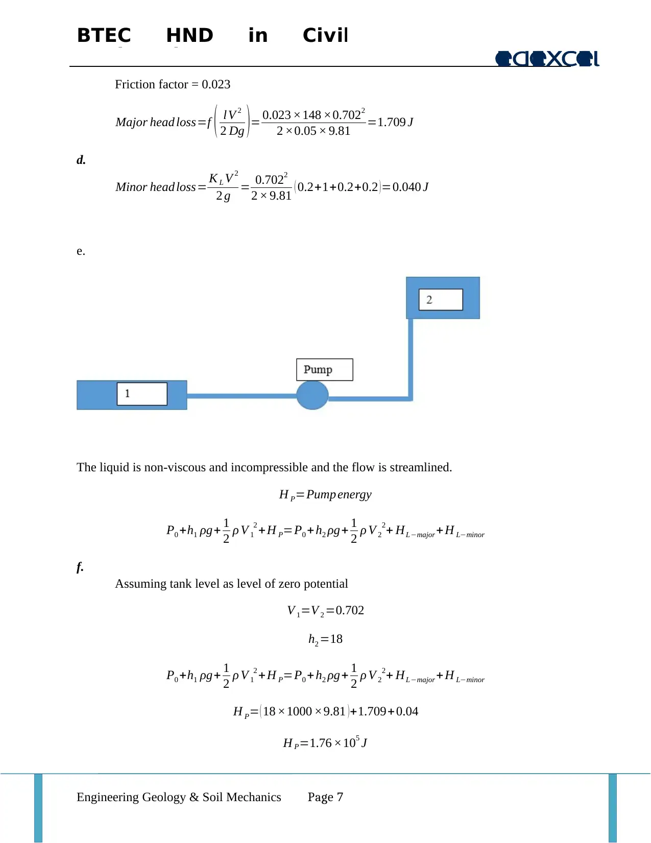
Project
AI Summary
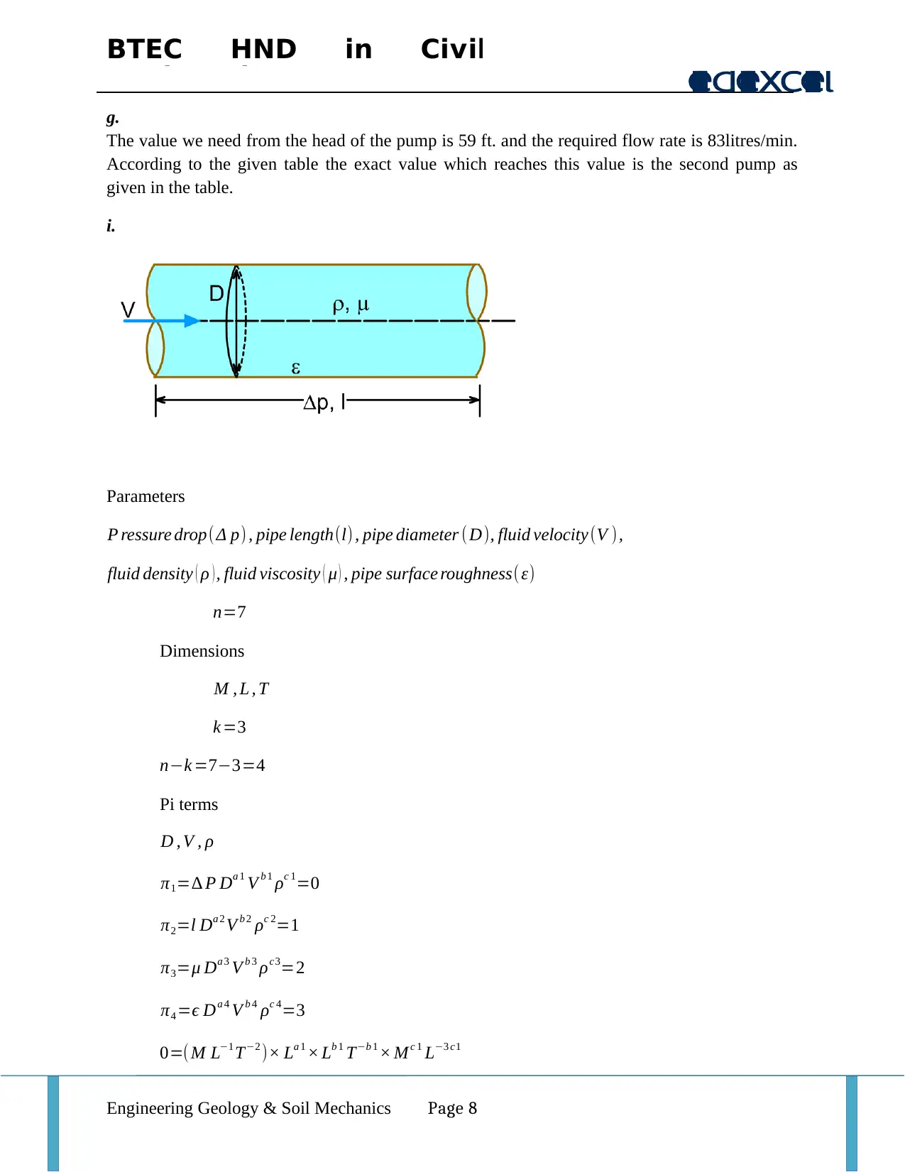
This assignment is a design project in civil engineering that analyzes fluid flow and pipe sizing. The project begins with a flow rate calculation and pipe selection based on the given parameters, including the determination of the pipe diameter using a flow rate of 30000 liters per day. It calculates the flow velocity and selects a 2-inch pipe as suitable, referencing a table of maximum allowable values. The assignment identifies the flow as turbulent and calculates the Reynolds number and friction factor. It then addresses pump selection, determining the required head and flow rate, and selects a pump based on these specifications. The project covers various aspects of fluid mechanics, including pipe sizing, flow regime identification, and pump selection, providing a comprehensive analysis for a civil engineering design scenario. The project also includes calculations for flow rate, velocity, and head loss, demonstrating an understanding of fluid dynamics principles.


1 out of 11


Your All-in-One AI-Powered Toolkit for Academic Success.
+13062052269
info@desklib.com
Available 24*7 on WhatsApp / Email
![[object Object]](/_next/static/media/star-bottom.7253800d.svg)
Copyright © 2020–2026 A2Z Services. All Rights Reserved. Developed and managed by ZUCOL.