Fluid Dynamics Report: Classical Mechanics, Shock Waves, Fire Plumes
VerifiedAdded on 2023/01/13
|10
|2195
|36
Report
AI Summary
This report delves into the core principles of fluid dynamics, commencing with an exploration of classical mechanics and fluid statics, including calculations of density, pressure, and temperature within a static air column. It then proceeds to dimensional analysis, demonstrating the derivation of the Reynolds number and the friction coefficient in pipe flow. The report further examines shock waves and detonation phenomena, describing shock wave tubes for detonation initiation, differentiating between deflagration and detonation, and illustrating the structure of a detonation wave. Finally, it analyzes fire plumes, outlining assumptions for the ideal fire plume model, presenting the fundamental equations, and deriving mass flow rate and temperature increments, with a comparison to other formulae.
Fluid Dynamics
Paraphrase This Document
Need a fresh take? Get an instant paraphrase of this document with our AI Paraphraser
Table of Contents
Classical Mechanics of fluids..........................................................................................................3
1.1 Fluid statics...........................................................................................................................3
2 Dimensional analysis....................................................................................................................4
2.1 Find the dimensions of Reynolds number, Re = ρul/μ, where ρ is the density, u is the
velocity, l is a characteristic lengths and μ is the dynamic viscosity of fluid............................4
2.2 Using the approach of dimensional analysis, derive the friction coefficient of pipe flow....4
3. Shock wave and detonation.........................................................................................................5
3.1 Shock wave tube is often used to study detonation...............................................................5
3.2 Deflagration and detonation are two forms of explosion......................................................5
4 Fire Plumes...................................................................................................................................8
4.1 Formulate the ideal fire plume..............................................................................................8
4.2 Through literature search, find out other formulae for the fire plume and compare them
with the formulae of the ideal fire plume and further give your comments on them.................9
References......................................................................................................................................10
Classical Mechanics of fluids
1.1 Fluid statics
A high rise building is 20m high. At the bottom of the building, pressure and temperature of the
air are 101.325 kPa and 298.15K, respectively. It is assumed that the air is static in this questions
a. Calculate density of the air at the building bottom.
P (pressure) = ρgh
ρ (density) = P/gh = 101.325/9.8*0.02 = 516.964285714 kg/m3
Density = 516.96 kg/m3
b. Assuming that density of the air is constant along the building height, calculate respectively
pressure and temperature of the air at the top of the building.
P = ρgh = 516.96 * 9.8 * 0.02 = 101.325 kPa
P = ρRT
T = P/ρR = 101.325 / 516.96 * 8.31 = 0.0325 K
Temperature = 0.0325 Kelvin
c. If temperature is constant along the building height, calculate pressure and density of the air at
the building top.
Pressure, P = ρgh = 516.96 * 9.8 * 0.02 = 101.32416 kPa
Density, ρ = P/gh = 101.32416/9.8*0.02 = 516.96 kg/m3
⊘ This is a preview!⊘
Do you want full access?
Subscribe today to unlock all pages.
Trusted by 1+ million students worldwide
2 Dimensional analysis
2.1 Find the dimensions of Reynolds number, Re = ρul/μ, where ρ is the density, u is the
velocity, l is a characteristic lengths and μ is the dynamic viscosity of fluid.
Dimensional formula is given by M0L0T0 where,
M = mass
L = length
T = time
Reynolds number, Re = ρul/μ = density * velocity * length * [dynamic viscosity]-1
=> Density, ρ = mass/volume = mass * [volume]-1
Dimensional formula of density = [M1 L-3 T0]
=> Velocity, u = displacement/time = displacement * [time]-1
Dimensional formula of velocity = [M0L1 T-1 ]
=> Lentgh, l = [L]
=> Dynamic viscosity, μ = distance between layers * force * [area * velocity]-1
Dimensional formula of dynamic viscosity = [L] * [M1L1T-2] * [L * L1T-1]-1 = [M1L-1T-1]
After substituting these equation, we get,
Re = [M1 L-3 T0] * [M0L1 T-1 ] * [L] * [M1L-1T-1]-1 = [M0L0T0]
Therefore, the dimensional formula of Reynolds number is [M0L0T0].
2.2 Using the approach of dimensional analysis, derive the friction coefficient of pipe flow.
By using approach of dimensional analysis, the friction coefficient is given by [M0L0T0],
Coefficient of friction, f = Frictional force * [normal force]-1
Force, F = mass * acceleration = mass * velocity * [time]-1
Velocity, v = displacement * [time]-1
Therefore, dimensions of force = [M] * [LT-1] * [T]-1 = [M1L1T-2]
Since, coefficient of friction = frictional force * [normal force]-1
f = [M1L1T-2] * [M1L1T-2]-1 = [M0L0T0]
Coefficient of friction, f = [M0L0T0]
Paraphrase This Document
Need a fresh take? Get an instant paraphrase of this document with our AI Paraphraser
3. Shock wave and detonation
3.1 Shock wave tube is often used to study detonation.
a. Devise a shock wave tube for direct initiation of detonation and explain each section of the
shock wave tube.
Detonation procedure can be described as a propulsion system with continuous burning
and impulse of combustible mixture. It incudes the increased interest of using it for the
detonation process in different technological devices including the concept of detonation engine
(DE). However, the initiation of detonation can be done through number of methods like
initiation at reflection of shock wave from a focusing surface (Tu, Yeoh and Liu, 2018). It also
consist the way of spatial initiation with use of multi-charge schema through a variation of an
amount of charges along with their spatial disposition from each other. Moreover, it consist
basic schemes of detonation engines like 'weapon' schema of pulsing detonation engine (PDE),
schema of supersonic pulsing detonation ramjet engine (PDRJE) and schema of a mixture
burning with the help of steady rotating detonation wave.
b. Give the formulae to calculate the speed of the shock wave at the time t = 0, i.e., just when the
diaphragm is broken down.
When time, T = 0, the velocity of shock waves is calculatde by the formula given below,
Velocity, v = u . kˆ + cskˆ
where, u is velocity of fluid and k is the wave vector, in one dimension,
v = u . cs
3.2 Deflagration and detonation are two forms of explosion.
a. Given the definitions of deflagration and detonation and discuss their difference.
Deflagration: The terms deflagration refers to explosive procedure develop shock wave
motive at less speed as compared to speed of sound in unreacted medium. It can be consider as
rapid auto combustion of particles of explosive as a surface phenomenon (Johnson, 2016).
Detonation: This can be described as a process of explosion which results into shock
wave moving at a speed more than the speed of sound in unreacted medium. It is known as an
extreme rapid and self-decomposition of an explosive accompanies through high pressure
temperature wave.
Deflagration Detonation
It is a kind of subsonic combustion driven via
thermal diffusion of heat as well as mass.
Whereas it is a supersonic combustion led by a
shock wave.
The speed of wave is observed to be typically
lower than 100m/s.
But in this process, speed can be exceed of
2000m/s.
It includes the main danger comes from
thermal damage.
It has danger of overpressure.
This consist standard combustion reaction,
travelling at accelerated rate (Soo, 2018).
Whereas Shock compresses F/A mixture, prior
to reaction zone, causing it to auto ignite as it
crosses the shock wave, vigorously fuelling the
reaction.
b. Illustrate the structure of a detonation and explain each section of the structure.
The synthesise of diamonds from carbon powder procedure consist use of explosives in
which high pressure shock wave developed which move into explosive, initiating reaction. The
detonation wave generated is given below.
⊘ This is a preview!⊘
Do you want full access?
Subscribe today to unlock all pages.
Trusted by 1+ million students worldwide
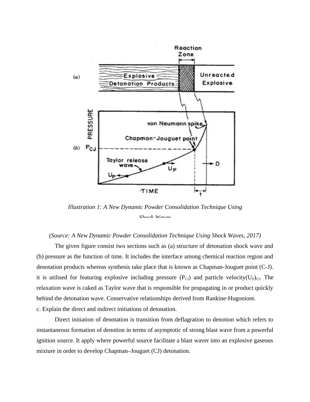
(Source: A New Dynamic Powder Consolidation Technique Using Shock Waves, 2017)
The given figure consist two sections such as (a) structure of detonation shock wave and
(b) pressure as the function of time. It includes the interface among chemical reaction region and
denotation products whereas synthesis take place that is known as Chapman-Jouguet point (C-J).
it is utilised for featuring explosive including pressure (PCJ) and particle velocity(UP)CJ. The
relaxation wave is caked as Taylor wave that is responsible for propagating in or product quickly
behind the detonation wave. Conservative relationships derived from Rankine-Hugoniont.
c. Explain the direct and indirect initiations of detonation.
Direct initiation of denotation is transition from deflagration to denotion which refers to
instantaneous formation of denotion in terms of asymptotic of strong blast wave from a powerful
ignition source. It apply where powerful source facilitate a blast waver into an explosive gaseous
mixture in order to develop Chapman–Jouguet (CJ) detonation.
Illustration 1: A New Dynamic Powder Consolidation Technique Using
Shock Waves
Paraphrase This Document
Need a fresh take? Get an instant paraphrase of this document with our AI Paraphraser
Indirect initiation detonation refers to a denotation that starts with deflagration in
explosive gaseous mixture which is a subsonic combustion wave which is ignited through
weaker ignition source (Kajishima and Taira, 2017).
4 Fire Plumes
4.1 Formulate the ideal fire plume
a. List the main assumptions for setup of the ideal fire plume model.
Assumptions of ideal fire plume model for FARSITE:
Fire spread is elliptical.
Fire spread in any direction is independent of fire front.
Fire acceleration is independent of fire behaviour and it is fuel dependent.
Fires will instantly attain the expected elliptical shape due to change in burning
situations.
The elliptical shapes are independent of fuel and only identified through resultant wind-
slope vector.
Variation in direction and wind speed at high frequency do not affect shape of elliptical
fire (Antar, 2019).
Origin of an elliptical fire is located at the rear focus on ellipse.
The spread of a continuous fire front can be around utilising finite number of points.
FARSITE model is not designed for determining if a fire will spread or not.
b. Write down and explain the basic equations for the ideal fire plume.
Equations for ideal fire plume is given here.
Simple smoke filling equation,
d (ρV) = mp
dt
where, ρ is density, V is volume and mp is flow rate of fire plume.
The volume of smoke layer, V = Ar (Hr - z)
where, Ar is floor area of room, Hr is ceiling area and z is smoke layer interface height.
- ρA, dz = mp
dt
Assumed plume mass flow rate formula,
mp = CmQf1/3z5/3
where, Cm is plume coefficient for which Zukoski proposed Cm= 0.076
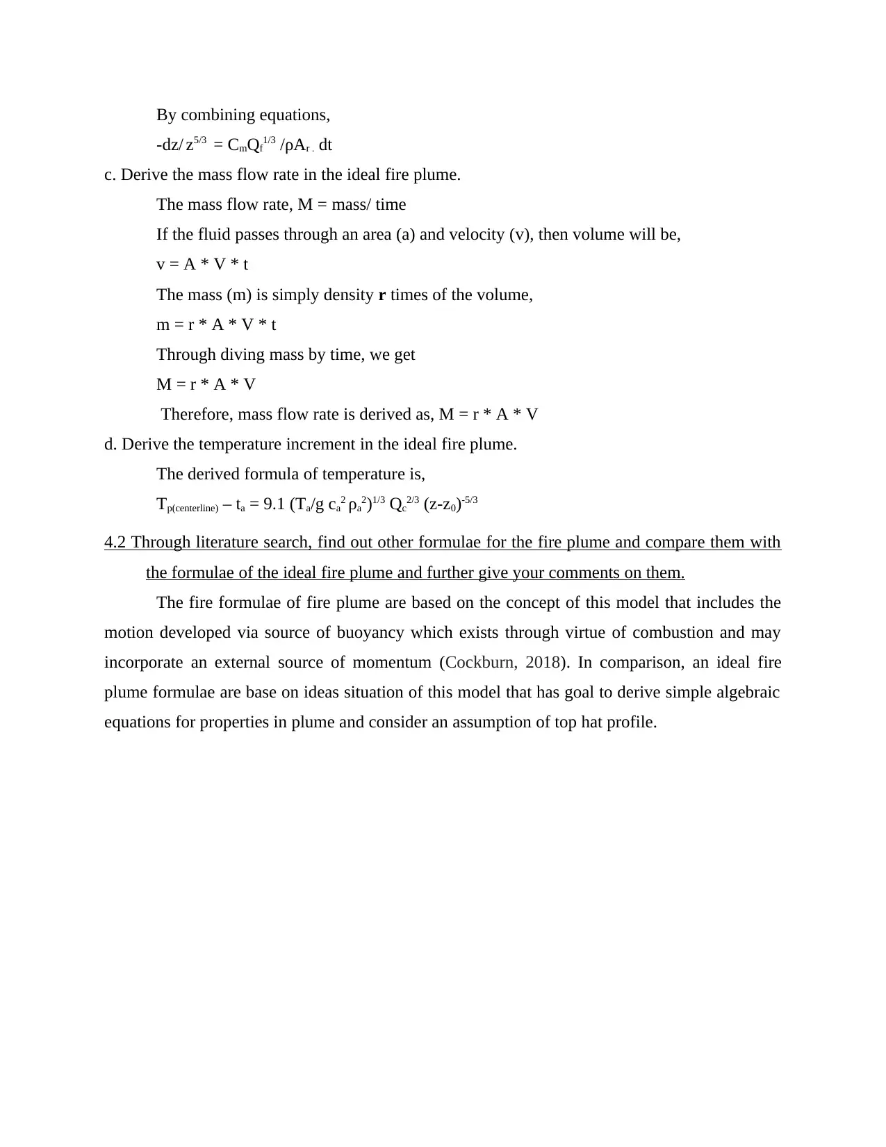
By combining equations,
-dz/ z5/3 = CmQf1/3 /ρAr . dt
c. Derive the mass flow rate in the ideal fire plume.
The mass flow rate, M = mass/ time
If the fluid passes through an area (a) and velocity (v), then volume will be,
v = A * V * t
The mass (m) is simply density r times of the volume,
m = r * A * V * t
Through diving mass by time, we get
M = r * A * V
Therefore, mass flow rate is derived as, M = r * A * V
d. Derive the temperature increment in the ideal fire plume.
The derived formula of temperature is,
Tp(centerline) – ta = 9.1 (Ta/g ca2 ρa2)1/3 Qc2/3 (z-z0)-5/3
4.2 Through literature search, find out other formulae for the fire plume and compare them with
the formulae of the ideal fire plume and further give your comments on them.
The fire formulae of fire plume are based on the concept of this model that includes the
motion developed via source of buoyancy which exists through virtue of combustion and may
incorporate an external source of momentum (Cockburn, 2018). In comparison, an ideal fire
plume formulae are base on ideas situation of this model that has goal to derive simple algebraic
equations for properties in plume and consider an assumption of top hat profile.
⊘ This is a preview!⊘
Do you want full access?
Subscribe today to unlock all pages.
Trusted by 1+ million students worldwide
References
Books and journals
Antar, B. N., 2019. Fundamentals of low gravity fluid dynamics and heat transfer. CRC press.
Cockburn, B., 2018. Discontinuous Galerkin methods for computational fluid dynamics.
Encyclopedia of Computational Mechanics Second Edition, pp.1-63.
Johnson, R. W. ed., 2016. Handbook of fluid dynamics. Crc Press.
Kajishima, T. and Taira, K., 2017. Computational fluid dynamics. Cham: Springer International
Publishing, (1).
Soo, S. L., 2018. Particulates and Continuum-Multiphase Fluid Dynamics: Multiphase Fluid
Dynamics. Routledge.
Tu, J., Yeoh, G. H. and Liu, C., 2018. Computational fluid dynamics: a practical approach.
Butterworth-Heinemann.
Online
A New Dynamic Powder Consolidation Technique Using Shock Waves. 2017. [Online].
Available through:<http://www.scielo.br/scielo.php?script=sci_arttext&pid=S1516-
14392017000800260>
1 out of 10


Your All-in-One AI-Powered Toolkit for Academic Success.
+13062052269
info@desklib.com
Available 24*7 on WhatsApp / Email
![[object Object]](/_next/static/media/star-bottom.7253800d.svg)
Unlock your academic potential
Copyright © 2020–2026 A2Z Services. All Rights Reserved. Developed and managed by ZUCOL.