MIET 2422 Fluid Mechanics: Research and Design of Piping Systems
VerifiedAdded on 2023/06/11
|13
|1988
|272
Report
AI Summary
This report provides a detailed analysis of piping systems, focusing on fluid mechanics principles relevant to mechanical systems. It covers key aspects such as pipe material selection, Reynolds number determination, head loss calculation using the Darcy equation, and system characteristic analysis. The report includes a practical example of calculating the optimal pipe diameter for a given flow rate and fluid velocity, and evaluates the performance of a specific pump (UNILIFT AP358-05-06-A1) within the system. The analysis extends to the creation of system curves, considering factors like friction losses and total head, and concludes with a discussion on the impact of pipe roughness on head loss and overall system performance. The selection of appropriate pumps is also included with reference to the selection charts provided.
Executive summary
A pipeline is a circular channel used to transport liquid from one area in the system then onto the
next. A pipeline comprises of circular shaped pipe filled with liquid, the process liquid, and the
valves and fittings used to coordinate the stream of liquid through the pipe in the operation. each
of these items influences the head loss in the pipeline. Most liquids used as a part of mechanical
applications are Newtonian, implying that their consistency does not change with the rate of
stream. Water, oils, solvents and oil based goods are cases of Newtonian liquids.
The effectiveness of convey of water through pipes is through installation of pumps in the same
channel of distribution having several components to push water throughout the system by a
force.
Pumps are classified as either rotodynamic pumps or positive displacement pumps, where the
rotodynamics pumps have rotor which is a rotating element through which the liquid passes, the
rotor is the impeller which will force water or liquid out of the casing through an outlet, whereas
the positive displacement pumps operates under the principal of mechanical and hydrostatic
pressure.
1
Paraphrase This Document
Need a fresh take? Get an instant paraphrase of this document with our AI Paraphraser
Choice of pipe
Pipe Material
Frequently the construction material confines the accessible pipe sizes and schedules. For
instance, polyvinyl chloride (PVC) pipe is accessible in huge numbers of indistinguishable sizes
from steel pipe, yet it is just accessible in schedule 40 and 80 pipe dimensions. In any case, the
internal pipe distance across (ID) can be extraordinary, giving fluctuating outcomes in head
misfortune.
Pipe Size
Pipe is accessible in various sizes and schedules or wall thicknesses. Clients regularly
erroneously utilize the pipe's ostensible size rather than the genuine ID instead of performing out
the head loss estimations.
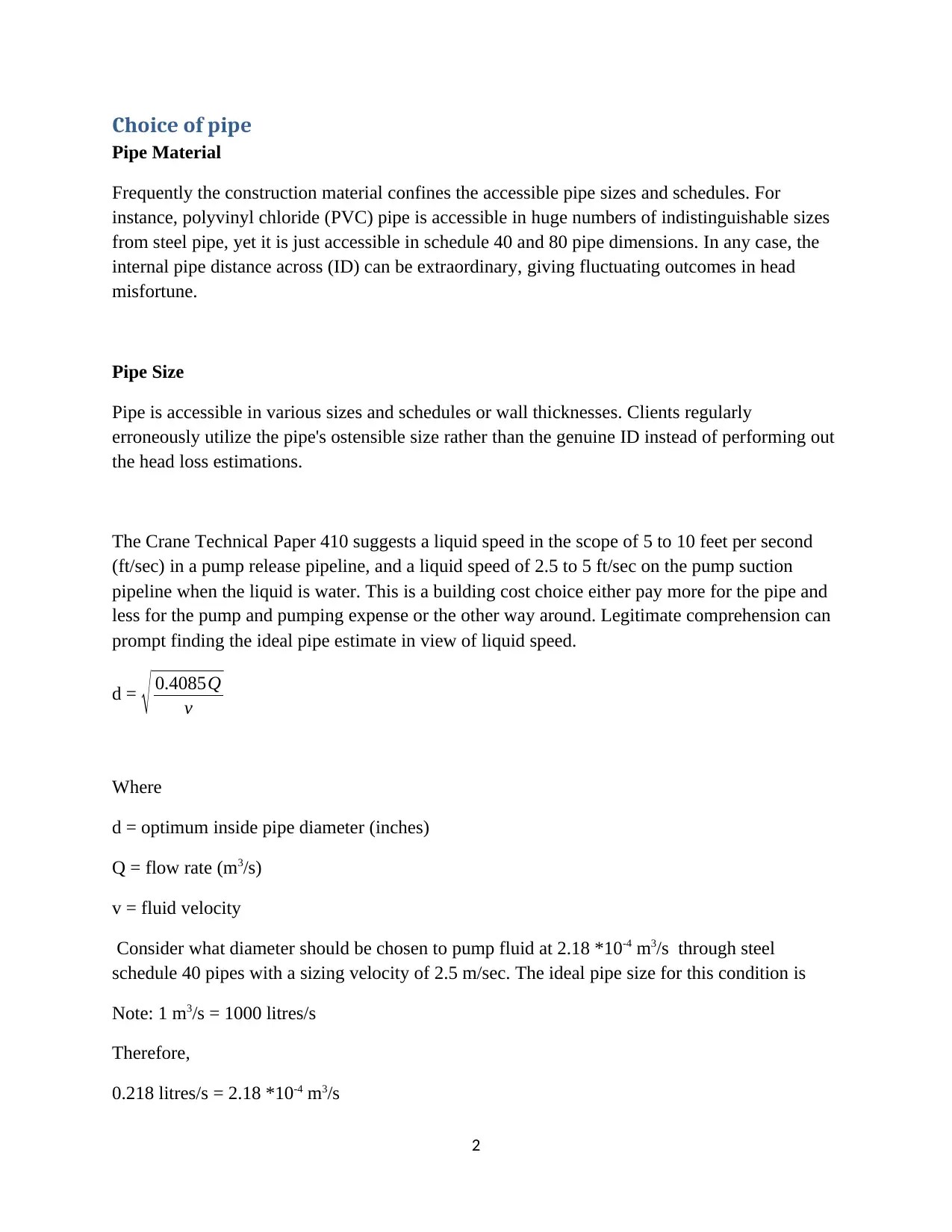
The Crane Technical Paper 410 suggests a liquid speed in the scope of 5 to 10 feet per second
(ft/sec) in a pump release pipeline, and a liquid speed of 2.5 to 5 ft/sec on the pump suction
pipeline when the liquid is water. This is a building cost choice either pay more for the pipe and
less for the pump and pumping expense or the other way around. Legitimate comprehension can
prompt finding the ideal pipe estimate in view of liquid speed.
d = √ 0.4085Q
v
Where
d = optimum inside pipe diameter (inches)
Q = flow rate (m3/s)
v = fluid velocity
Consider what diameter should be chosen to pump fluid at 2.18 *10-4 m3/s through steel
schedule 40 pipes with a sizing velocity of 2.5 m/sec. The ideal pipe size for this condition is
Note: 1 m3/s = 1000 litres/s
Therefore,
0.218 litres/s = 2.18 *10-4 m3/s
2
Pipe Material
Frequently the construction material confines the accessible pipe sizes and schedules. For
instance, polyvinyl chloride (PVC) pipe is accessible in huge numbers of indistinguishable sizes
from steel pipe, yet it is just accessible in schedule 40 and 80 pipe dimensions. In any case, the
internal pipe distance across (ID) can be extraordinary, giving fluctuating outcomes in head
misfortune.
Pipe Size
Pipe is accessible in various sizes and schedules or wall thicknesses. Clients regularly
erroneously utilize the pipe's ostensible size rather than the genuine ID instead of performing out
the head loss estimations.
The Crane Technical Paper 410 suggests a liquid speed in the scope of 5 to 10 feet per second
(ft/sec) in a pump release pipeline, and a liquid speed of 2.5 to 5 ft/sec on the pump suction
pipeline when the liquid is water. This is a building cost choice either pay more for the pipe and
less for the pump and pumping expense or the other way around. Legitimate comprehension can
prompt finding the ideal pipe estimate in view of liquid speed.
d = √ 0.4085Q
v
Where
d = optimum inside pipe diameter (inches)
Q = flow rate (m3/s)
v = fluid velocity
Consider what diameter should be chosen to pump fluid at 2.18 *10-4 m3/s through steel
schedule 40 pipes with a sizing velocity of 2.5 m/sec. The ideal pipe size for this condition is
Note: 1 m3/s = 1000 litres/s
Therefore,
0.218 litres/s = 2.18 *10-4 m3/s
2
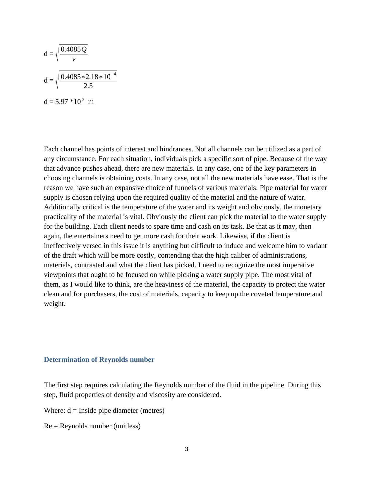
d = √ 0.4085Q
v
d = √ 0.4085∗2.18∗10−4
2.5
d = 5.97 *10-3 m
Each channel has points of interest and hindrances. Not all channels can be utilized as a part of
any circumstance. For each situation, individuals pick a specific sort of pipe. Because of the way
that advance pushes ahead, there are new materials. In any case, one of the key parameters in
choosing channels is obtaining costs. In any case, not all the new materials have ease. That is the
reason we have such an expansive choice of funnels of various materials. Pipe material for water
supply is chosen relying upon the required quality of the material and the nature of water.
Additionally critical is the temperature of the water and its weight and obviously, the monetary
practicality of the material is vital. Obviously the client can pick the material to the water supply
for the building. Each client needs to spare time and cash on its task. Be that as it may, then
again, the entertainers need to get more cash for their work. Likewise, if the client is
ineffectively versed in this issue it is anything but difficult to induce and welcome him to variant
of the draft which will be more costly, contending that the high caliber of administrations,
materials, contrasted and what the client has picked. I need to recognize the most imperative
viewpoints that ought to be focused on while picking a water supply pipe. The most vital of
them, as I would like to think, are the heaviness of the material, the capacity to protect the water
clean and for purchasers, the cost of materials, capacity to keep up the coveted temperature and
weight.
Determination of Reynolds number
The first step requires calculating the Reynolds number of the fluid in the pipeline. During this
step, fluid properties of density and viscosity are considered.
Where: d = Inside pipe diameter (metres)
Re = Reynolds number (unitless)
3
⊘ This is a preview!⊘
Do you want full access?
Subscribe today to unlock all pages.
Trusted by 1+ million students worldwide
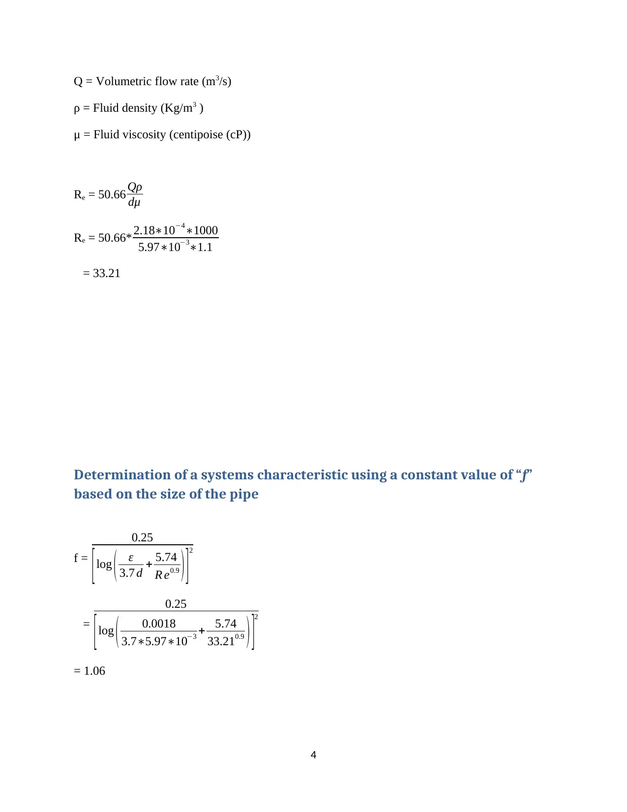
Q = Volumetric flow rate (m3/s)
ρ = Fluid density (Kg/m3 )
μ = Fluid viscosity (centipoise (cP))
Re = 50.66 Qρ
dμ
Re = 50.66* 2.18∗10−4∗1000
5.97∗10−3∗1.1
= 33.21
Determination of a systems characteristic using a constant value of “f”
based on the size of the pipe
f =
0.25
[log ( ε
3.7 d + 5.74
R e0.9 ) ]2
=
0.25
[log ( 0.0018
3.7∗5.97∗10−3 + 5.74
33.210.9 ) ]2
= 1.06
4
Paraphrase This Document
Need a fresh take? Get an instant paraphrase of this document with our AI Paraphraser
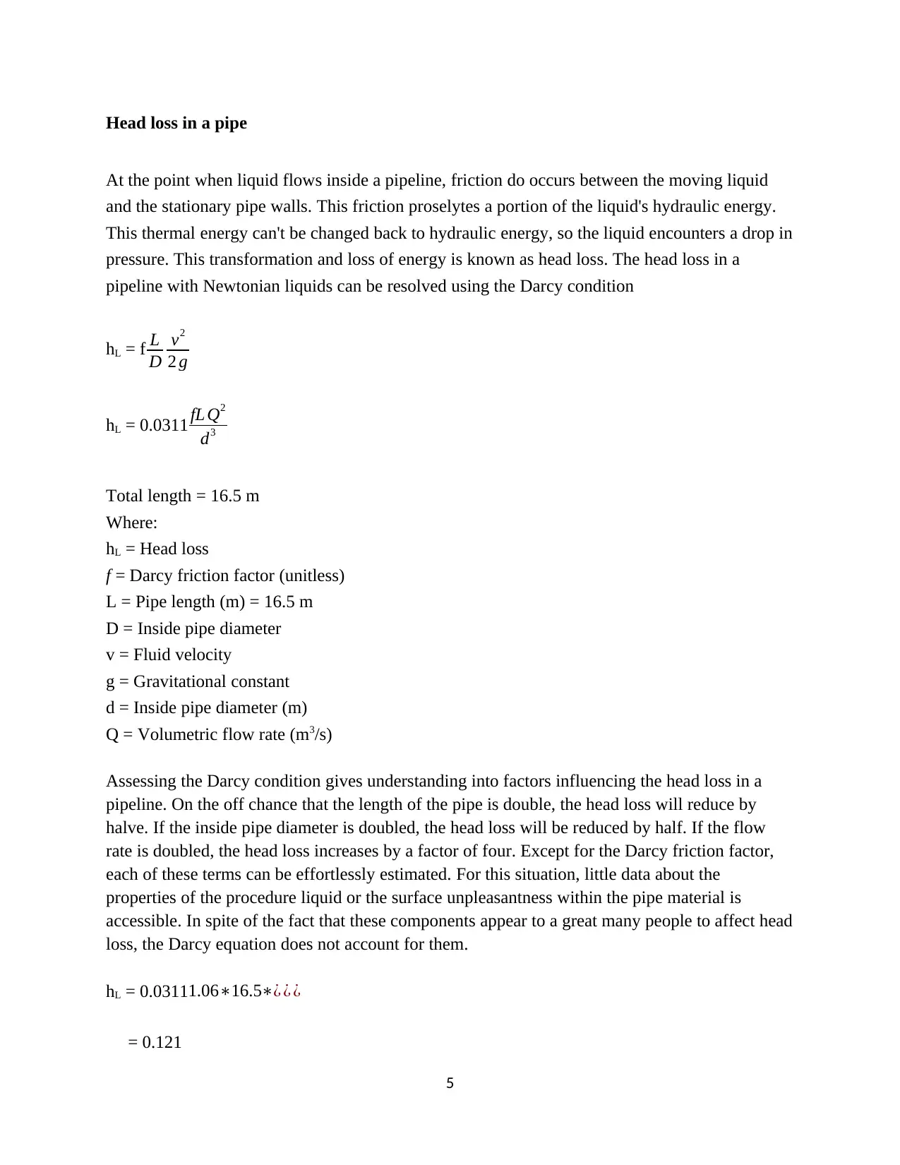
Head loss in a pipe
At the point when liquid flows inside a pipeline, friction do occurs between the moving liquid
and the stationary pipe walls. This friction proselytes a portion of the liquid's hydraulic energy.
This thermal energy can't be changed back to hydraulic energy, so the liquid encounters a drop in
pressure. This transformation and loss of energy is known as head loss. The head loss in a
pipeline with Newtonian liquids can be resolved using the Darcy condition
hL = f L
D
v2
2 g
hL = 0.0311 fL Q2
d3
Total length = 16.5 m
Where:
hL = Head loss
f = Darcy friction factor (unitless)
L = Pipe length (m) = 16.5 m
D = Inside pipe diameter
v = Fluid velocity
g = Gravitational constant
d = Inside pipe diameter (m)
Q = Volumetric flow rate (m3/s)
Assessing the Darcy condition gives understanding into factors influencing the head loss in a
pipeline. On the off chance that the length of the pipe is double, the head loss will reduce by
halve. If the inside pipe diameter is doubled, the head loss will be reduced by half. If the flow
rate is doubled, the head loss increases by a factor of four. Except for the Darcy friction factor,
each of these terms can be effortlessly estimated. For this situation, little data about the
properties of the procedure liquid or the surface unpleasantness within the pipe material is
accessible. In spite of the fact that these components appear to a great many people to affect head
loss, the Darcy equation does not account for them.
hL = 0.03111.06∗16.5∗¿ ¿ ¿
= 0.121
5

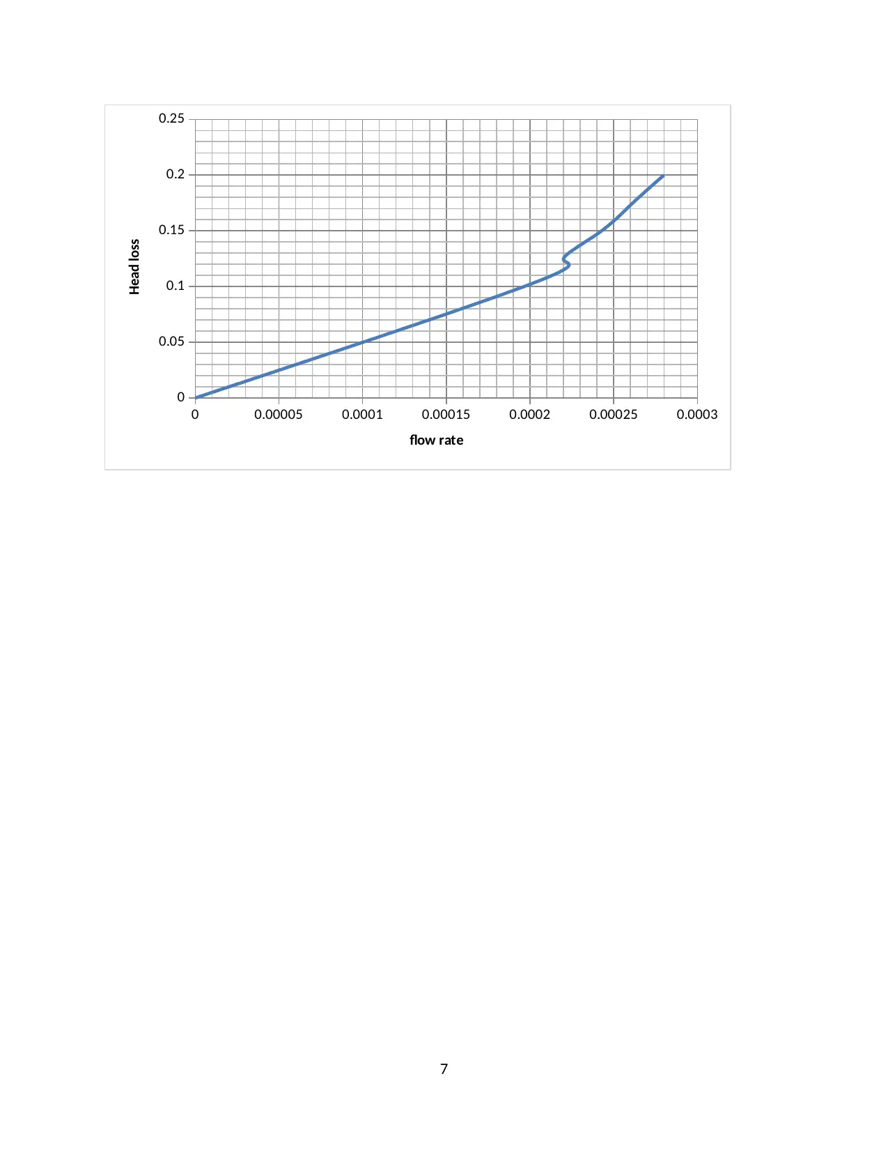
Q (m3/s) 2.0 *10-4 2.2*10-4 2.4*10-4 2.6*10-4 2.8*10-4
hL (m) 0.102 0.124 0.147 0.173 0.2
A graph of head loss against flow rate
6
hL (m) 0.102 0.124 0.147 0.173 0.2
A graph of head loss against flow rate
6
⊘ This is a preview!⊘
Do you want full access?
Subscribe today to unlock all pages.
Trusted by 1+ million students worldwide
0 0.00005 0.0001 0.00015 0.0002 0.00025 0.0003
0
0.05
0.1
0.15
0.2
0.25
flow rate
Head loss
7
0
0.05
0.1
0.15
0.2
0.25
flow rate
Head loss
7
Paraphrase This Document
Need a fresh take? Get an instant paraphrase of this document with our AI Paraphraser
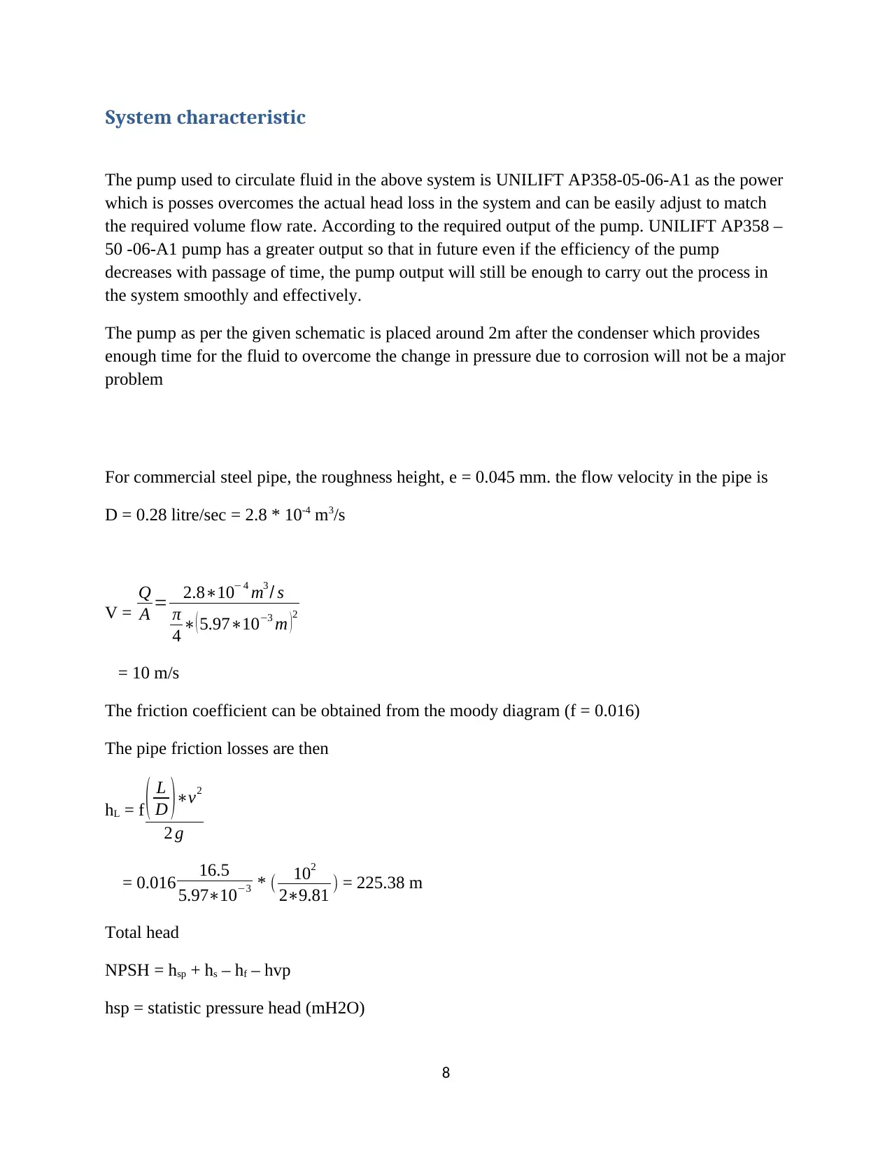
System characteristic
The pump used to circulate fluid in the above system is UNILIFT AP358-05-06-A1 as the power
which is posses overcomes the actual head loss in the system and can be easily adjust to match
the required volume flow rate. According to the required output of the pump. UNILIFT AP358 –
50 -06-A1 pump has a greater output so that in future even if the efficiency of the pump
decreases with passage of time, the pump output will still be enough to carry out the process in
the system smoothly and effectively.
The pump as per the given schematic is placed around 2m after the condenser which provides
enough time for the fluid to overcome the change in pressure due to corrosion will not be a major
problem
For commercial steel pipe, the roughness height, e = 0.045 mm. the flow velocity in the pipe is
D = 0.28 litre/sec = 2.8 * 10-4 m3/s
V =
Q
A = 2.8∗10− 4 m3 / s
π
4 ∗( 5.97∗10−3 m )2
= 10 m/s
The friction coefficient can be obtained from the moody diagram (f = 0.016)
The pipe friction losses are then
hL = f ( L
D )∗v2
2 g
= 0.016 16.5
5.97∗10−3 * ( 102
2∗9.81 ) = 225.38 m
Total head
NPSH = hsp + hs – hf – hvp
hsp = statistic pressure head (mH2O)
8
hs = elevation difference (m)
hvp = vapour pressure of liquid (mH2O)
hf = frictio loss (m)
NPSH = 1.5 + 3.5 + 3.3 + 225.38 = 233.68 m
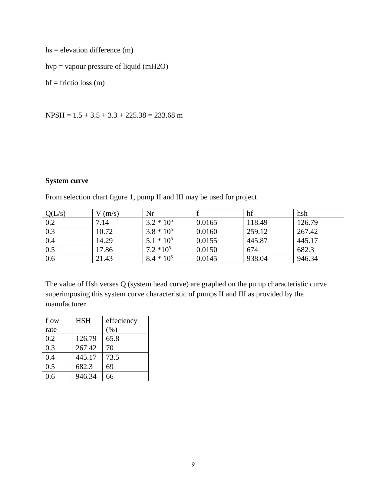
System curve
From selection chart figure 1, pump II and III may be used for project
Q(L/s) V (m/s) Nr f hf hsh
0.2 7.14 3.2 * 105 0.0165 118.49 126.79
0.3 10.72 3.8 * 105 0.0160 259.12 267.42
0.4 14.29 5.1 * 105 0.0155 445.87 445.17
0.5 17.86 7.2 *105 0.0150 674 682.3
0.6 21.43 8.4 * 105 0.0145 938.04 946.34
The value of Hsh verses Q (system head curve) are graphed on the pump characteristic curve
superimposing this system curve characteristic of pumps II and III as provided by the
manufacturer
flow
rate
HSH effeciency
(%)
0.2 126.79 65.8
0.3 267.42 70
0.4 445.17 73.5
0.5 682.3 69
0.6 946.34 66
9
hvp = vapour pressure of liquid (mH2O)
hf = frictio loss (m)
NPSH = 1.5 + 3.5 + 3.3 + 225.38 = 233.68 m
System curve
From selection chart figure 1, pump II and III may be used for project
Q(L/s) V (m/s) Nr f hf hsh
0.2 7.14 3.2 * 105 0.0165 118.49 126.79
0.3 10.72 3.8 * 105 0.0160 259.12 267.42
0.4 14.29 5.1 * 105 0.0155 445.87 445.17
0.5 17.86 7.2 *105 0.0150 674 682.3
0.6 21.43 8.4 * 105 0.0145 938.04 946.34
The value of Hsh verses Q (system head curve) are graphed on the pump characteristic curve
superimposing this system curve characteristic of pumps II and III as provided by the
manufacturer
flow
rate
HSH effeciency
(%)
0.2 126.79 65.8
0.3 267.42 70
0.4 445.17 73.5
0.5 682.3 69
0.6 946.34 66
9
⊘ This is a preview!⊘
Do you want full access?
Subscribe today to unlock all pages.
Trusted by 1+ million students worldwide
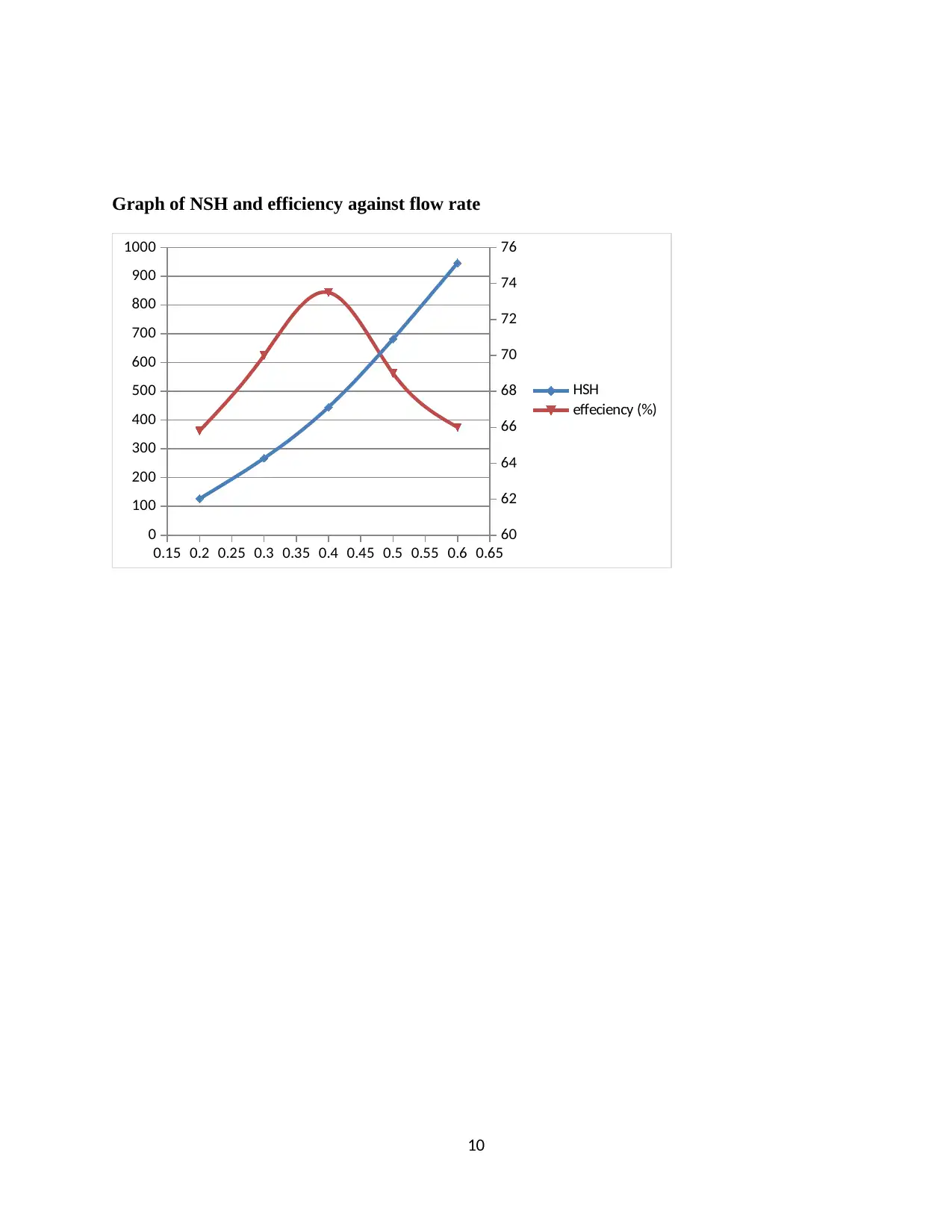
Graph of NSH and efficiency against flow rate
0.15 0.2 0.25 0.3 0.35 0.4 0.45 0.5 0.55 0.6 0.65
0
100
200
300
400
500
600
700
800
900
1000
60
62
64
66
68
70
72
74
76
HSH
effeciency (%)
10
0.15 0.2 0.25 0.3 0.35 0.4 0.45 0.5 0.55 0.6 0.65
0
100
200
300
400
500
600
700
800
900
1000
60
62
64
66
68
70
72
74
76
HSH
effeciency (%)
10
Paraphrase This Document
Need a fresh take? Get an instant paraphrase of this document with our AI Paraphraser
Performance of the system will varying with time
To move a given volume of fluid through a pipe requires a specific measure of
vitality. A vitality or weight distinction must exist to make the fluid move. A segment
of that vitality is lost to the protection from stream. This protection from stream is
called head misfortune because of rubbing.
The state of within a pipe additionally greatly affects the head loss of the stream of
fluid. The rougher it is, the thicker the layer of non-moving or moderate moving fluid
close to the pipe divider. This diminishes within breadth of the pipe, expanding the
speed of the fluid. With the expansion in speed comes an increment in erosion
misfortunes.
11
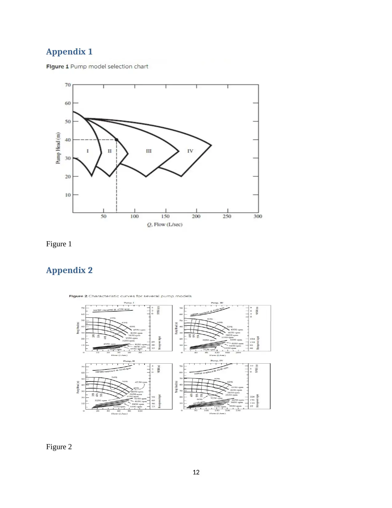
Appendix 1
Figure 1
Appendix 2
Figure 2
12
Figure 1
Appendix 2
Figure 2
12
⊘ This is a preview!⊘
Do you want full access?
Subscribe today to unlock all pages.
Trusted by 1+ million students worldwide
1 out of 13


Your All-in-One AI-Powered Toolkit for Academic Success.
+13062052269
info@desklib.com
Available 24*7 on WhatsApp / Email
![[object Object]](/_next/static/media/star-bottom.7253800d.svg)
Unlock your academic potential
Copyright © 2020–2025 A2Z Services. All Rights Reserved. Developed and managed by ZUCOL.