Comparative Study of Pumped Hydro-Power and Flywheel Energy Storage
VerifiedAdded on 2023/06/15
|45
|7041
|411
Report
AI Summary
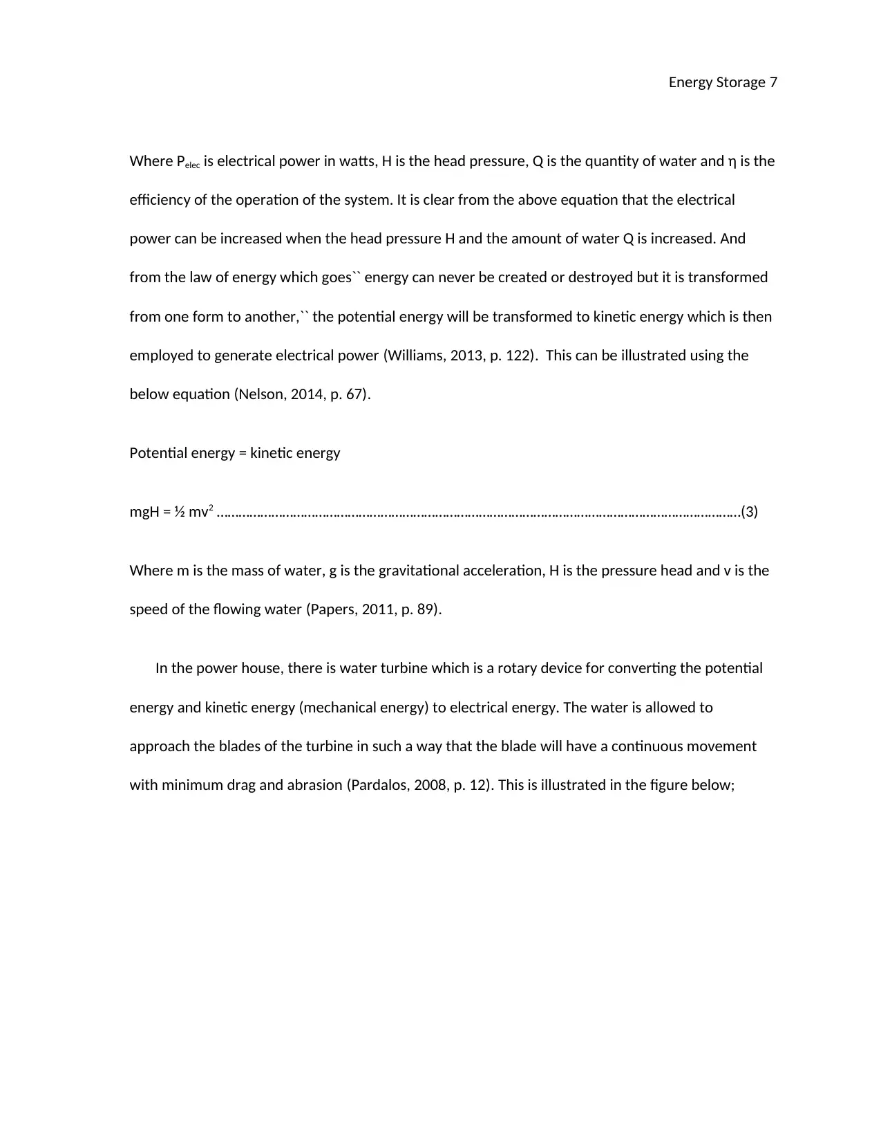
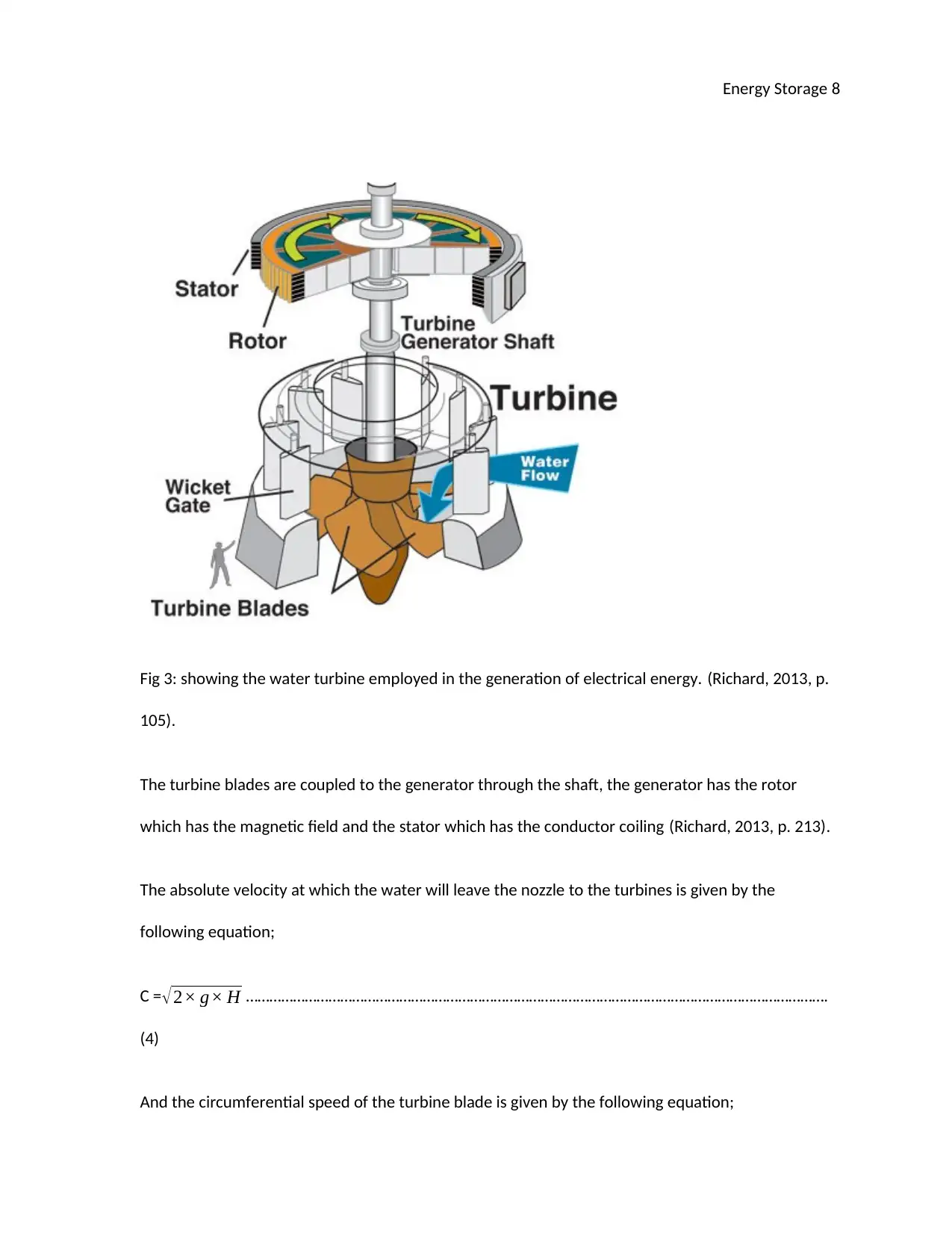
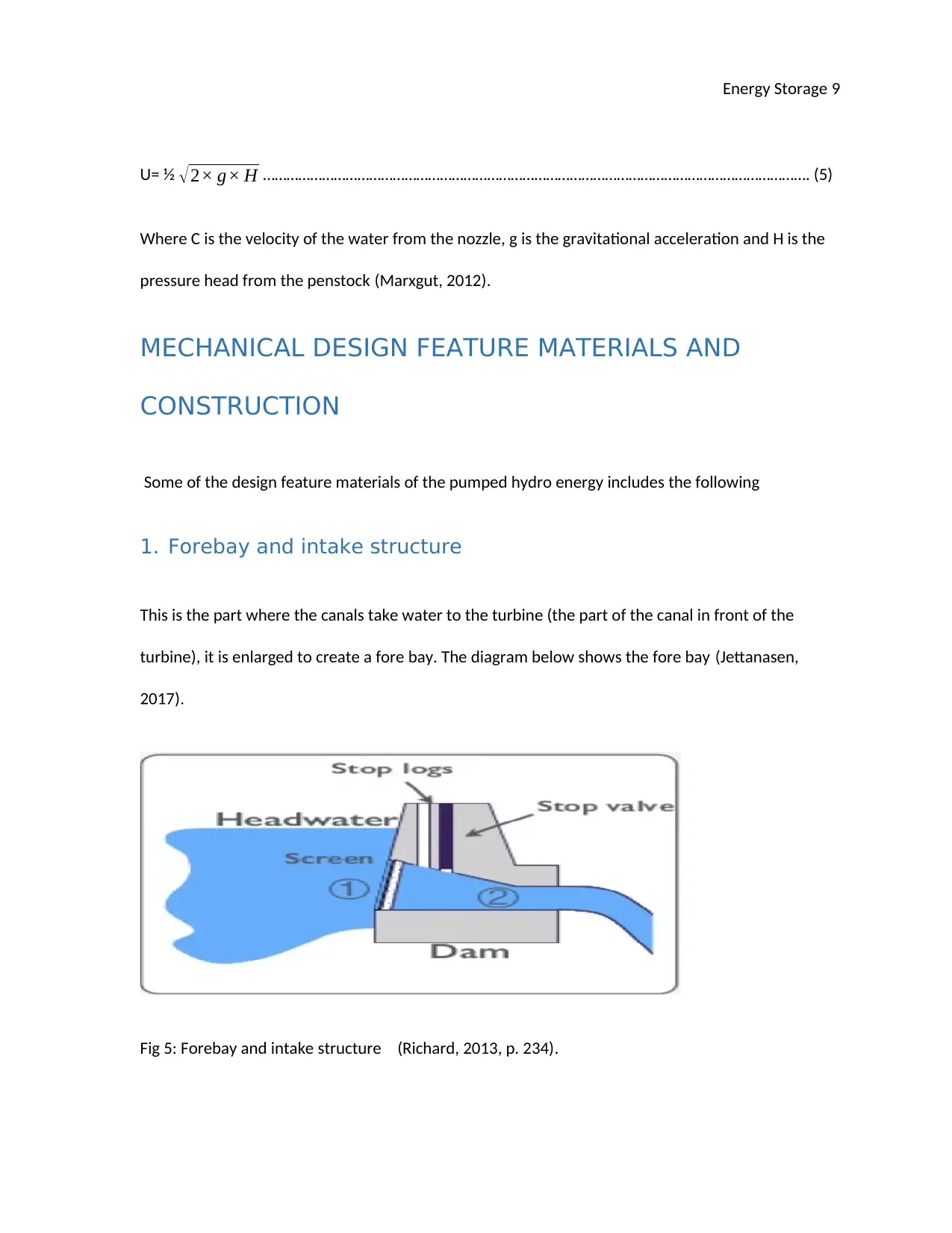
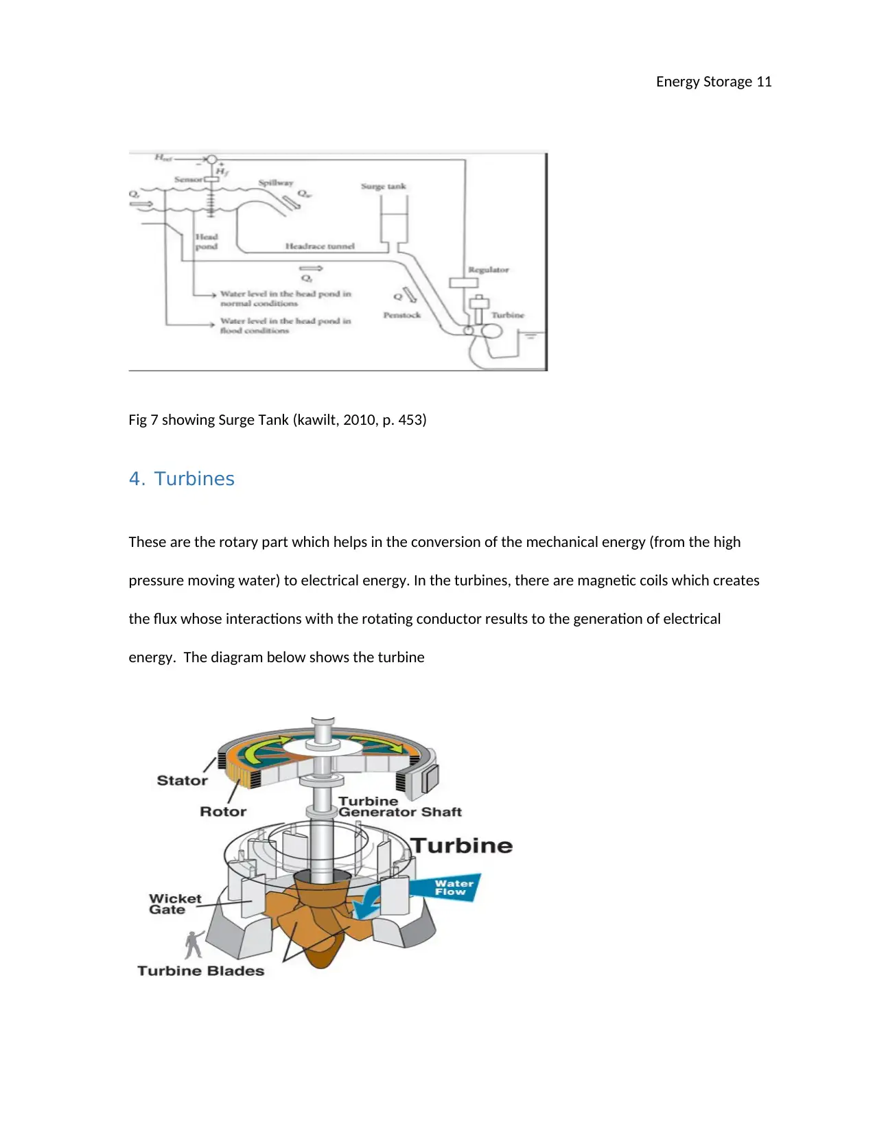
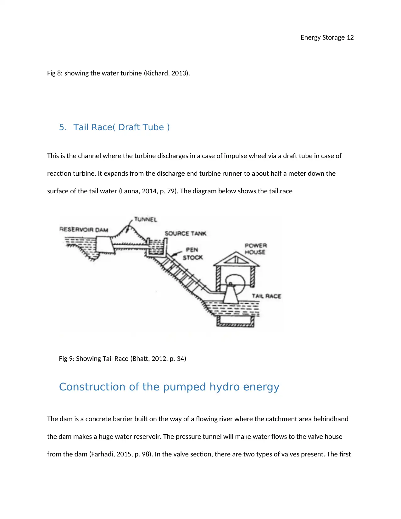
This report provides a detailed analysis of two energy storage technologies: pumped hydro-power and flywheel energy storage. The pumped hydro-power section explains the principle of operation, which involves storing water in a tail race pond during low load periods and pumping it back to a head reservoir using excess energy. It covers mechanical design features such as forebays, head races, surge tanks, turbines, and tail races, along with construction aspects and current operational applications. Design considerations, including power delivery, discharge rates, and turbine speed calculations, are also discussed. The flywheel energy storage section explores the use of a rotating wheel to store kinetic energy, detailing its operation, materials used in construction, and applications. The report highlights the conversion of mechanical or electrical energy into rotational kinetic energy and its subsequent retrieval when needed. Overall, the report offers a comprehensive overview of the principles, design, and applications of these two energy storage systems.

Energy Storage 1
ENERGY STORAGE
By Name
Course
Instructor
Institution
Location
Date
Contents
ENERGY STORAGE
By Name
Course
Instructor
Institution
Location
Date
Contents
Paraphrase This Document
Need a fresh take? Get an instant paraphrase of this document with our AI Paraphraser

Energy Storage 2
PUMPED HYDRO-POWER ENERGY.......................................................................................................2
PRINCIPLE OPERATION OF THE PUMPED HYDRO....................................................................................2
MECHANICAL DESIGN FEATURE MATERIALS AND CONSTRUCTION......................................................6
1. Forebay and intake structure...........................................................................................................6
2. Head Race........................................................................................................................................7
3. Surge Tank.......................................................................................................................................7
4. Turbines...........................................................................................................................................8
5. Tail Race( Draft Tube ).....................................................................................................................8
Construction of the pumped hydro energy...........................................................................................9
Application and where currently operational.....................................................................................10
Design....................................................................................................................................................10
Summary.............................................................................................................................................12
FLYWHEEL ENERGY STORAGE.............................................................................................................13
OPERATION............................................................................................................................................13
MATERIALS USED IN DESIGN.................................................................................................................15

Energy Storage 3
CONSTRUCTION OF FLYWHEEL..............................................................................................................15
WHERE THIS IS EMPLOYED....................................................................................................................16
DESIGN..................................................................................................................................................16
REAL VIEW OF FLYWHEEL......................................................................................................................19
SUMMARY.............................................................................................................................................19
⊘ This is a preview!⊘
Do you want full access?
Subscribe today to unlock all pages.

Trusted by 1+ million students worldwide

Energy Storage 4
Question 1
PUMPED HYDRO-POWER ENERGY
PRINCIPLE OPERATION OF THE PUMPED HYDRO
The water moving via the turbine is stored in a `` tail race pond`` for the period of low load. The
water is then pumped back to the head reservoir by the aid of the extra energy present. The water
pumped back can then be employed again in the production of electrical energy during the periods of
peak load (McMurry, 2015).
Real view of pumped hydroelectric power plant
Fig: Showing a pumped hydroelectric power plant (Richard, W., 2013)
Paraphrase This Document
Need a fresh take? Get an instant paraphrase of this document with our AI Paraphraser

Energy Storage 5
Fig: showing a real view for pumped hydro power energy
The assembly of the pumped hydro system can be illustrated as in the diagram below;
Fig 1: Showing the assembly of the pumped hydro technology. (Webinars, 2012).
The pumped hydro technology is used at the places where the amount of water present is inadequate
therefore water flowing to the turbines is first stored in the reservoir (Webinars, 2012). During
the ``charge`` period electric motor will drive the pump having more water from a lower to the
upper reservoir, there are some losses which are associated with this which makes this
technology to have an efficiency of about 82%. The diagram below summarises the process
(Bany, 2012).

Energy Storage 6
Fig 2: showing the working principle of the pumped hydro. (pakistan, 2013, p. 123).
The storage capacity of this technology is shown by the following equation;
Q=V× H × ρ × η × g ……………………………………………………………………………………………………………….(1)
Where Q is the storage capacity, V is the volume of the reservoir, H is the upper reservoir elevation,
η is the efficiency.
The amount of storage in the pumped hydro technology is much higher than what is stored in the
battery technology (Bhatt, 2012, p. 177). The amount of power per day (kWh/ day) needed to pump
a specific amount of water per day can be given by the following equations;
Pelec= 0.1885× H × Q
η
……………………………………………………………………………………………………………………………..(2)
⊘ This is a preview!⊘
Do you want full access?
Subscribe today to unlock all pages.

Trusted by 1+ million students worldwide

Energy Storage 7
Where Pelec is electrical power in watts, H is the head pressure, Q is the quantity of water and η is the
efficiency of the operation of the system. It is clear from the above equation that the electrical
power can be increased when the head pressure H and the amount of water Q is increased. And
from the law of energy which goes`` energy can never be created or destroyed but it is transformed
from one form to another,`` the potential energy will be transformed to kinetic energy which is then
employed to generate electrical power (Williams, 2013, p. 122). This can be illustrated using the
below equation (Nelson, 2014, p. 67).
Potential energy = kinetic energy
mgH = ½ mv2 ………………………………………………………………………………………………………………………………(3)
Where m is the mass of water, g is the gravitational acceleration, H is the pressure head and v is the
speed of the flowing water (Papers, 2011, p. 89).
In the power house, there is water turbine which is a rotary device for converting the potential
energy and kinetic energy (mechanical energy) to electrical energy. The water is allowed to
approach the blades of the turbine in such a way that the blade will have a continuous movement
with minimum drag and abrasion (Pardalos, 2008, p. 12). This is illustrated in the figure below;
Paraphrase This Document
Need a fresh take? Get an instant paraphrase of this document with our AI Paraphraser

Energy Storage 8
Fig 3: showing the water turbine employed in the generation of electrical energy. (Richard, 2013, p.
105).
The turbine blades are coupled to the generator through the shaft, the generator has the rotor
which has the magnetic field and the stator which has the conductor coiling (Richard, 2013, p. 213).
The absolute velocity at which the water will leave the nozzle to the turbines is given by the
following equation;
C = √2× g× H ………………………………………………………………………………………………………………………………….
(4)
And the circumferential speed of the turbine blade is given by the following equation;

Energy Storage 9
U= ½ √2× g× H …………………………………………………………………………………………………………………………. (5)
Where C is the velocity of the water from the nozzle, g is the gravitational acceleration and H is the
pressure head from the penstock (Marxgut, 2012).
MECHANICAL DESIGN FEATURE MATERIALS AND
CONSTRUCTION
Some of the design feature materials of the pumped hydro energy includes the following
1. Forebay and intake structure
This is the part where the canals take water to the turbine (the part of the canal in front of the
turbine), it is enlarged to create a fore bay. The diagram below shows the fore bay (Jettanasen,
2017).
Fig 5: Forebay and intake structure (Richard, 2013, p. 234).
⊘ This is a preview!⊘
Do you want full access?
Subscribe today to unlock all pages.

Trusted by 1+ million students worldwide

Energy Storage 10
2. Head Race
This is the part of the micro pumped hydro power which carries water to the turbine from the
reservoir (Al-Tai, 2015, p. 78). The selection of the pressure conduit will depend upon the condition
of the site of construction. The diagram below shows the head Race
Fig 6: Showing the head Race (Richard, 2013, p. 67).
3. Surge Tank
This is a storage reservoir put at some opening made on along the pipe line to help receive the
rejected flow in case the pipe lines are abruptly closed by valves put at its steep end. The diagram
below shows the surge Tank (Peek, 2015, p. 342).
Paraphrase This Document
Need a fresh take? Get an instant paraphrase of this document with our AI Paraphraser

Energy Storage 11
Fig 7 showing Surge Tank (kawilt, 2010, p. 453)
4. Turbines
These are the rotary part which helps in the conversion of the mechanical energy (from the high
pressure moving water) to electrical energy. In the turbines, there are magnetic coils which creates
the flux whose interactions with the rotating conductor results to the generation of electrical
energy. The diagram below shows the turbine

Energy Storage 12
Fig 8: showing the water turbine (Richard, 2013).
5. Tail Race( Draft Tube )
This is the channel where the turbine discharges in a case of impulse wheel via a draft tube in case of
reaction turbine. It expands from the discharge end turbine runner to about half a meter down the
surface of the tail water (Lanna, 2014, p. 79). The diagram below shows the tail race
Fig 9: Showing Tail Race (Bhatt, 2012, p. 34)
Construction of the pumped hydro energy
The dam is a concrete barrier built on the way of a flowing river where the catchment area behindhand
the dam makes a huge water reservoir. The pressure tunnel will make water flows to the valve house
from the dam (Farhadi, 2015, p. 98). In the valve section, there are two types of valves present. The first
⊘ This is a preview!⊘
Do you want full access?
Subscribe today to unlock all pages.

Trusted by 1+ million students worldwide
1 out of 45

Your All-in-One AI-Powered Toolkit for Academic Success.
+13062052269
info@desklib.com
Available 24*7 on WhatsApp / Email
Unlock your academic potential
Copyright © 2020–2025 A2Z Services. All Rights Reserved. Developed and managed by ZUCOL.