FM Radio Repeater Design: An Advanced Electronics Coursework Project

Verified

Added on  2023/06/04

|11
|1391
|98
Report
AI Summary
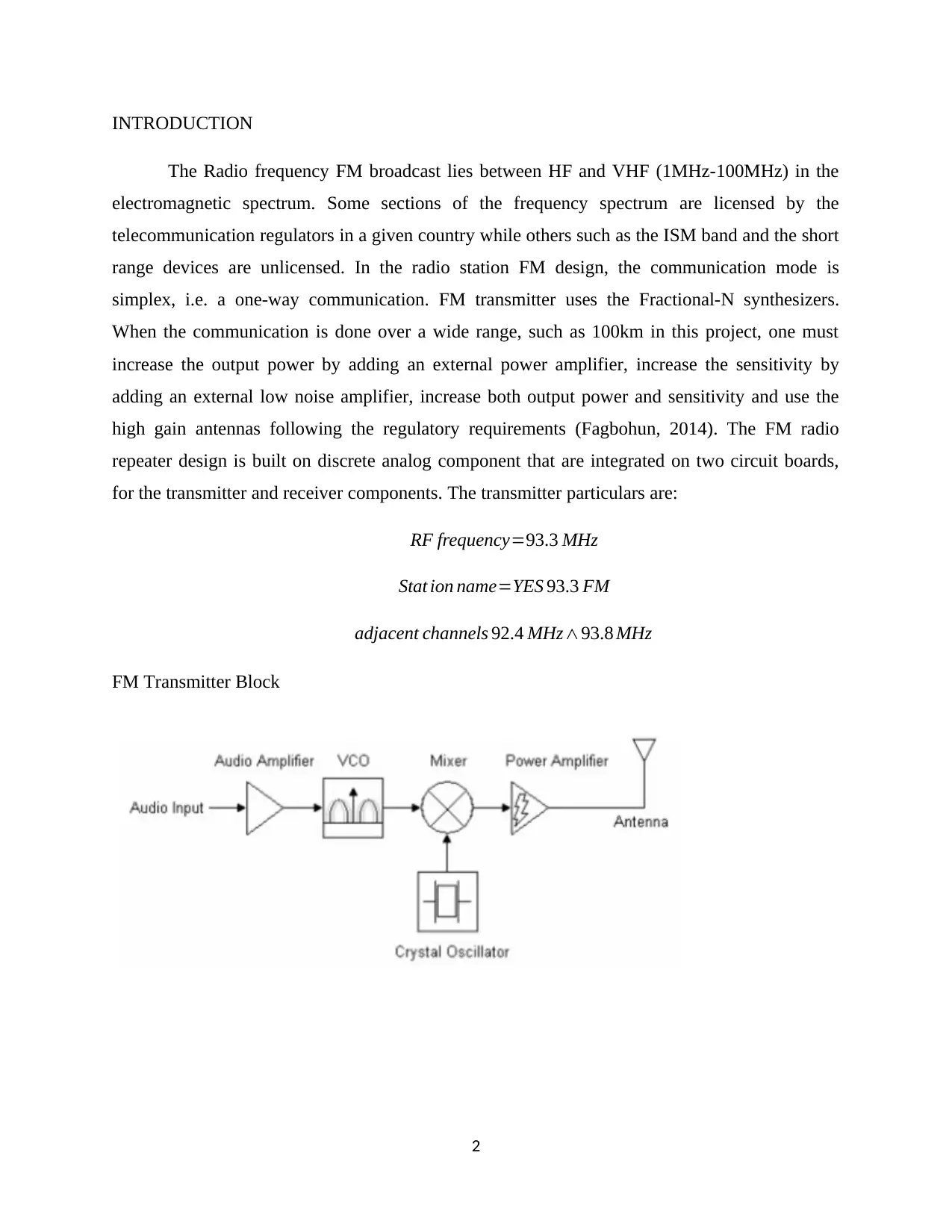
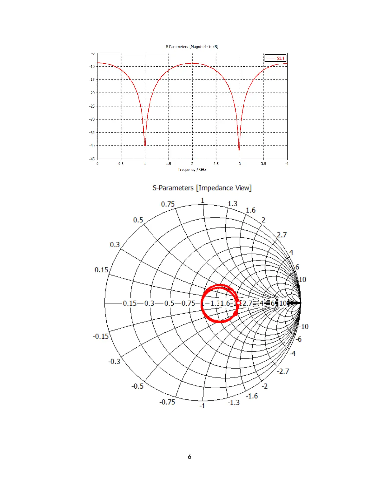
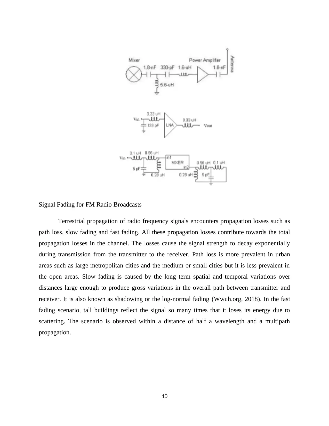
This report presents the design of an FM radio repeater, focusing on the transmitter section, bandwidth calculation of the band-pass filter (BPF), RF power amplifier design, and L-matching network using a Smith chart for impedance matching. It addresses the importance of power calculation to ensure sufficient power transmission at the antenna, working backward from the antenna power of 100dBm with reasonable assumptions of antenna gain to determine the input power. The report also covers practical component selection, complete circuit design, signal fading considerations for FM radio broadcasts, and PCB layout considerations using Proteus Professional 8, comparing PCB antennas with alternatives like whip and chip antennas. References to relevant academic papers and online resources are included to support the design and analysis.
Document Page
FM RADIO REPEATER DESIGN
ADVANCED ELECTRONICS COURSEWORK ASSIGNMENT
STUDENT NAME
STUDENT ID NUMBER
INSTITUTIONAL AFFILIATION
LOCATION (STATE, COUNTRY)
PROFESSOR (INSTRUCTOR)
DATE OF SUBMISSION
1
tabler-icon-diamond-filled.svg

Paraphrase This Document

Need a fresh take? Get an instant paraphrase of this document with our AI Paraphraser
Document Page
INTRODUCTION
The Radio frequency FM broadcast lies between HF and VHF (1MHz-100MHz) in the
electromagnetic spectrum. Some sections of the frequency spectrum are licensed by the
telecommunication regulators in a given country while others such as the ISM band and the short
range devices are unlicensed. In the radio station FM design, the communication mode is
simplex, i.e. a one-way communication. FM transmitter uses the Fractional-N synthesizers.
When the communication is done over a wide range, such as 100km in this project, one must
increase the output power by adding an external power amplifier, increase the sensitivity by
adding an external low noise amplifier, increase both output power and sensitivity and use the
high gain antennas following the regulatory requirements (Fagbohun, 2014). The FM radio
repeater design is built on discrete analog component that are integrated on two circuit boards,
for the transmitter and receiver components. The transmitter particulars are:
RF frequency=93.3 MHz
Stat ion name=YES 93.3 FM
adjacent channels 92.4 MHz93.8 MHz
FM Transmitter Block
2
Document Page
The chart below shows that the selection of radio station frequency falls in the correct
frequency band. It is illustrated as,
Figure 1 The Frequency Band & application Chart [source: FM Broadcast ElectronicsHub]
FM Receiver Block
FM RADIO REPEATER DESIGN
(i) Transmit RF power amplifier
3
Document Page
An external power amplifier is required to boost the signal power for transmission. A
higher signal power is responsible for transmitting a signal to greater lengths. The
mixer and the power amplifier can be designed using the capacitors and an
operational amplifier as shown in the circuit below,
The power amplifier is supplied with 20dB of gain to compensate for the weak mixer
output. For a maximum power transfer between the mixer and the power amplifier,
the matching network circuit above is used. A transmission line’s characteristic
impedance is achieved using the 1.8nF coupling capacitor system into the 50-ohm
system. It uses the Gali-5 amplifier network to perform the amplification (Electronics,
2018).
(ii) Matching network (IMN & OMN) using smith chart (Torrungrueng and Mekathikom,
2015)
4
tabler-icon-diamond-filled.svg

Paraphrase This Document

Need a fresh take? Get an instant paraphrase of this document with our AI Paraphraser
Document Page
(iii) Antenna matching
An antenna is quite crucial especially for long range communication. A quarter-
wave antenna is a good solution when you wish to perform impedance matching on
the circuit (Torrungrueng and Mekathikom, 2015).
The value of impedance is given as,
Z1 = Z0 RL
The width of the micro strip antenna or the regular antenna strip is given such that
the quarter wave antenna performs impedance matching for the entire circuit. The
quarter wave antenna is connected to a load or the matching network which acts
as a load (Khan, Azim and Islam, 2014). The S-parameter is that of a quarter
wave transformer which is represented as,
5
Document Page
6
Document Page
Using the quarter wave stub, it is considered that the
ZL=0 ( short circuit ) , Zi=Z0 tan βLinfiniteL= λ
4 , 3 λ
4 ,
For a matched load, the return loss is expressed as,
RL=20 log |Γ0|
(iv) Power calculation
Antenna Power=100 dBm
Length=200 m
The reflection coefficient is given as,
Γ s= Zg Z0
Zg Z0
Γ0 = ZlZo
ZlZ0
Γ out=Γ ( d=l ) =Γs e2 ist
Γ¿=Γ ( d =l ) =Γ0 e2 ist
(v) RF Band-pass filter design
BW
B W c
= f
f c
f c= f 1 f 2
f c= 92.493.8=93.0974 MHz
(vi) Power budget and Free space path loss (FSPL) calculation
7
tabler-icon-diamond-filled.svg

Paraphrase This Document

Need a fresh take? Get an instant paraphrase of this document with our AI Paraphraser
Document Page
According to the radio range of transmission, it is expected that the signal power will
lower and hence a repeater is needed between the transmitter and the receiver. To
compute the free space path loss for signal propagation, the Friis transmission
equation is used,
Pr =Pt +Gt + Gr +20 log ( λ
4 π )20 log d
Pr = Pt Gt Gr λ2
( 4 π ) 2 d2
Pr = ( 45 dBm ) ( 1.2 dBi )λ2
( 4 π )2 (100)2 =3.41959105 λ2
Where the receiver power is based on the transmit power, transmit gain, receiver gain,
wavelength, and the distance between the transmitter and the receiver. When there is a
6dB improvement, the distance is double while doubling the frequency reduces the range
by half (wwuh.org, 2018).
(vii) PCB Layout considerations
A PCB antenna is implemented as it is very cost-effective; it has a suitable size
required for the low frequencies, has good performance and is complicated to make
good designs. The PCB design is made using the Proteus Professional 8 software
which designs the FM radio components on the IRIS page and represents the PCB
outline on the ARES page. Other alternatives to the PCB implementations are the
whip antennas and the chip antennas (Evans, n.d.).
An example of an implemented PCB FM transmitter and receiver is as illustrated
in the image below,
8
Document Page
Figure 2 The PCB Illustration for FM transmitter and receiver [source: ElectronicsHub]
(viii) Practical components selection
(ix) Complete circuit design
9
Document Page
Signal Fading for FM Radio Broadcasts
Terrestrial propagation of radio frequency signals encounters propagation losses such as
path loss, slow fading and fast fading. All these propagation losses contribute towards the total
propagation losses in the channel. The losses cause the signal strength to decay exponentially
during transmission from the transmitter to the receiver. Path loss is more prevalent in urban
areas such as large metropolitan cities and the medium or small cities but it is less prevalent in
the open areas. Slow fading is caused by the long term spatial and temporal variations over
distances large enough to produce gross variations in the overall path between transmitter and
receiver. It is also known as shadowing or the log-normal fading (Wwuh.org, 2018). In the fast
fading scenario, tall buildings reflect the signal so many times that it loses its energy due to
scattering. The scenario is observed within a distance of half a wavelength and a multipath
propagation.
10
tabler-icon-diamond-filled.svg

Paraphrase This Document

Need a fresh take? Get an instant paraphrase of this document with our AI Paraphraser
Document Page
REFERENCES
Electronics-notes.com. (2018). FM Dipole Antenna | Aerial Design | Electronics Notes. [online]
Available at: https://www.electronics-notes.com/articles/antennas-propagation/dipole-antenna/
fm-dipole-antenna.php [Accessed 11 Oct. 2018].
Evans, B. (2009). Chebyshev quarter-wave stepped Balun transformer. Electronics Letters,
9(22), p.514
Fagbohun, O, O. (2014). Studies of Electric field distribution of uhf television signal in Ekiti
State, Nigeria. IOSR Journal of Electronics and Communication Engineering (IOSR-JECE) e-
ISSN: 2278-2834, p-ISSN 2278-8735, Volume 9, Issue 2 Ver. V (Mar-Apr), pp 111-
121;American National Engineering Database ANED-DDL14.2834/iosr-jece-
S0925111121;DOI(Digital Object Identifier)10.9790/2834- 0925111121 .
Khan, N., Azim, A. and Islam, S. (2014). Radiation Characteristics of a Quarter-Wave Monopole
Antenna above Virtual Ground. Journal of Clean Energy Technologies, 2(4), pp.339-342.
Torrungrueng, D. and Mekathikom, T. (2015). Forbidden regions of L-section impedance
matching networks on Meta-Smith charts for conjugately characteristic-impedance transmission
lines. Microwave and Optical Technology Letters, 57(4), pp.874-879.
Wwuh.org. (2018). FM Reception Tips | wwuh.org. [online] Available at:
http://www.wwuh.org/00489-fm-reception-tips [Accessed 11 Oct. 2018].
11
chevron_up_icon
1 out of 11
circle_padding
hide_on_mobile
zoom_out_icon
[object Object]