ULS and SLS Foundation Design for Te Rewa Rewa Footbridge
VerifiedAdded on 2023/06/07
|3
|821
|466
Report
AI Summary
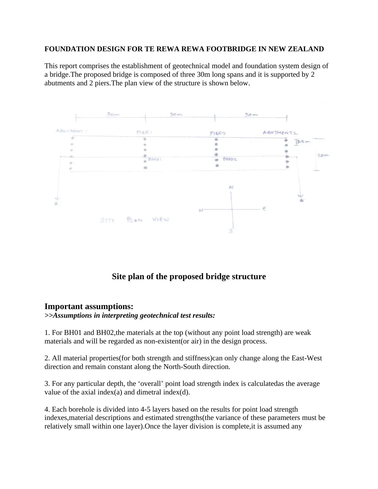
This report details the geotechnical model and foundation system design for the Te Rewa Rewa Footbridge in New Zealand, a three-span bridge supported by abutments and piers. It outlines key assumptions in interpreting geotechnical test results, including material properties and point load strength indexes. The design criteria focus on Ultimate Limit State (ULS) and Serviceability Limit State (SLS) conditions, adhering to New Zealand standards. The analysis considers pile settlement and horizontal deflection, with specific attention to shale layers and their properties. The conclusion highlights the generally good subsurface conditions and the adequacy of the current pile configuration to support the structure.

FOUNDATION DESIGN FOR TE REWA REWA FOOTBRIDGE IN NEW ZEALAND
This report comprises the establishment of geotechnical model and foundation system design of
a bridge.The proposed bridge is composed of three 30m long spans and it is supported by 2
abutments and 2 piers.The plan view of the structure is shown below.
Site plan of the proposed bridge structure
Important assumptions:
>>Assumptions in interpreting geotechnical test results:
1. For BH01 and BH02,the materials at the top (without any point load strength) are weak
materials and will be regarded as non-existent(or air) in the design process.
2. All material properties(for both strength and stiffness)can only change along the East-West
direction and remain constant along the North-South direction.
3. For any particular depth, the ‘overall’ point load strength index is calculatedas the average
value of the axial index(a) and dimetral index(d).
4. Each borehole is divided into 4-5 layers based on the results for point load strength
indexes,material descriptions and estimated strengths(the variance of these parameters must be
relatively small within one layer).Once the layer division is complete,it is assumed any
Paraphrase This Document
Need a fresh take? Get an instant paraphrase of this document with our AI Paraphraser

individual layer has only one constant point load strength index which is the average value of all
‘overall’ point load strength indexes in this layer.
5. In the calculation of pile bearing capacity,the ultimate end bearing of any foundation system is
assumed to be 3 times the UCS value at the depth where the pier or abutment is founded on the
rock.
6. In the acquisition of horizontal and vertical modulus E values,a distinction is made between
UCS at horizontal and vertical directions.UCS_horizontal is assumed to be 17 times axial point
load strength index (a) and UCS_vertical is assumed to be 17 times the value of dimetral point
load strength index (d).
7. The underlying assumption is that the relative UCS of a rock is proportional to the relative
stiffness of the rock.The only exceptions to this assumption occur when the calculated UCS turns
out to be larger than the maximum UCS value defined in the design table,in which case only the
maximum E values in the stiffness range in the design table would be adopted.
>>Assumptions in the analysis and design of pile system:
1. There are in total 6 piles(abutments or piers) along North-South direction in one particular
East-West position and the tributary width for each pile is exactly 3.5m.
2. All pile systems are assumed to have free head, meaning the load will be evenly distributed
among the piles but the settlement and the lateral deflection will differ from one pile to
another.The most critical settlement case occurs at the midpoint along the bridge width while the
bridge edges witnessed the largest horizontal deflection of the structure.
3.In the horizontal deflection analysis,all shales within 16m below the ground surface are
recognized as clay with an equivalent undrained cohesion Cu of 0.5 times the UCS.
4.If a pile foundation penetrates into different rock layers of the rock,the overall stiffness and
strength parameters used in analysis is the weighted average stiffness of all reached layers(based
on layer thickness).
This assumption applies to both Young’s modulus E(MPa) and undrained shear strength
Cu(kPa).
5.The value of poisson’s ratio have negligence influences on the analysis of vertical settlement
and horizontal deflections.
6.All pile length in the design is measured from the top of the proposed headstock.

DESIGN CRITERIA:
Analysis and design process is performed on abutment A and pier1 only using ULS(ultimate
limit state) and SLS(serviceability limit state) criteria which are specified in the following
(NewZealand standard 1726-1999).
1. For ULS conditions, the footing is to be designed using the geotechnical strength factors
stipulated in AS 2159.The ultimate state loades (including vertical forces,horizontal forces and
total bending moment) must be lower than the factored capacities of the pile.
2. For SLS condition,the pile settlement is to be limited to 10mm and the horizontal deflection is
to be limited to 20mm.
CONCLUSIONS:
1.The site investigation shows that the subsurface condition is generally good for supporting
major structures with primarily Class III and class II shale(reasonably stiff and strong) existing in
the investigated site.
2.The current configuration of pile distribution (6 pile each row,4 rows in total) is capable of
supporting the structure with integrity.
⊘ This is a preview!⊘
Do you want full access?
Subscribe today to unlock all pages.

Trusted by 1+ million students worldwide
1 out of 3
Your All-in-One AI-Powered Toolkit for Academic Success.
+13062052269
info@desklib.com
Available 24*7 on WhatsApp / Email
Unlock your academic potential
Copyright © 2020–2025 A2Z Services. All Rights Reserved. Developed and managed by ZUCOL.