Experimental Investigation: Forced Convection Through a Pipe
VerifiedAdded on Β 2022/08/09
|12
|1486
|227
Practical Assignment
AI Summary
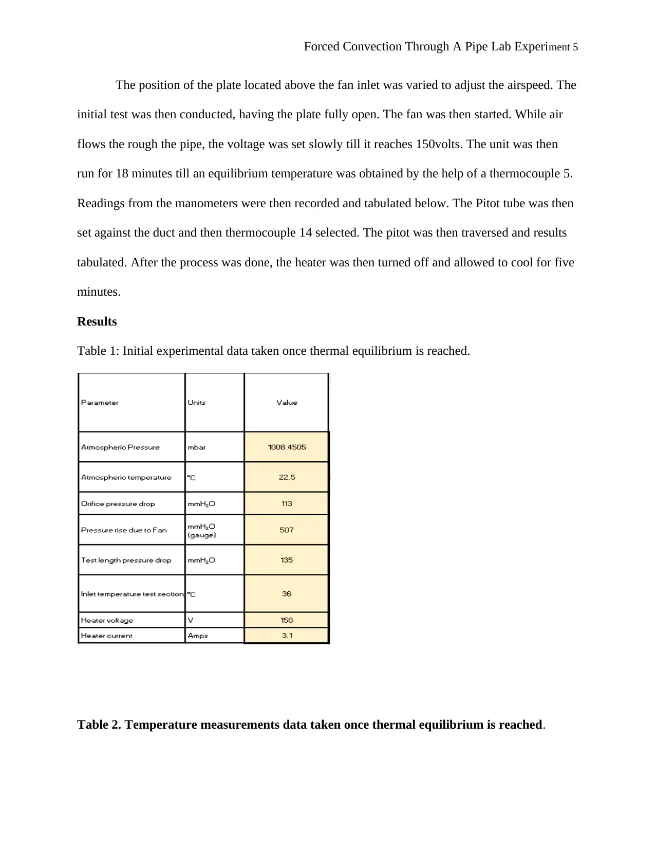
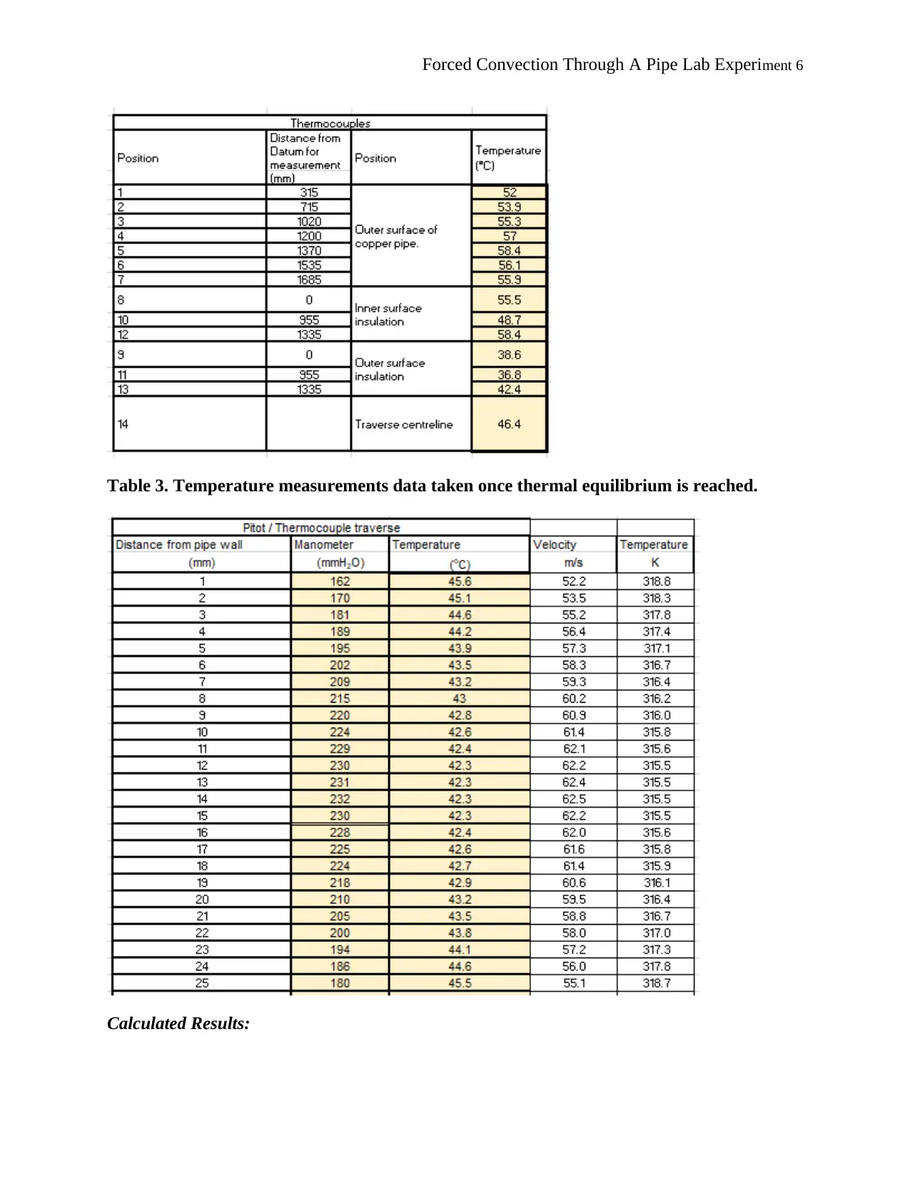
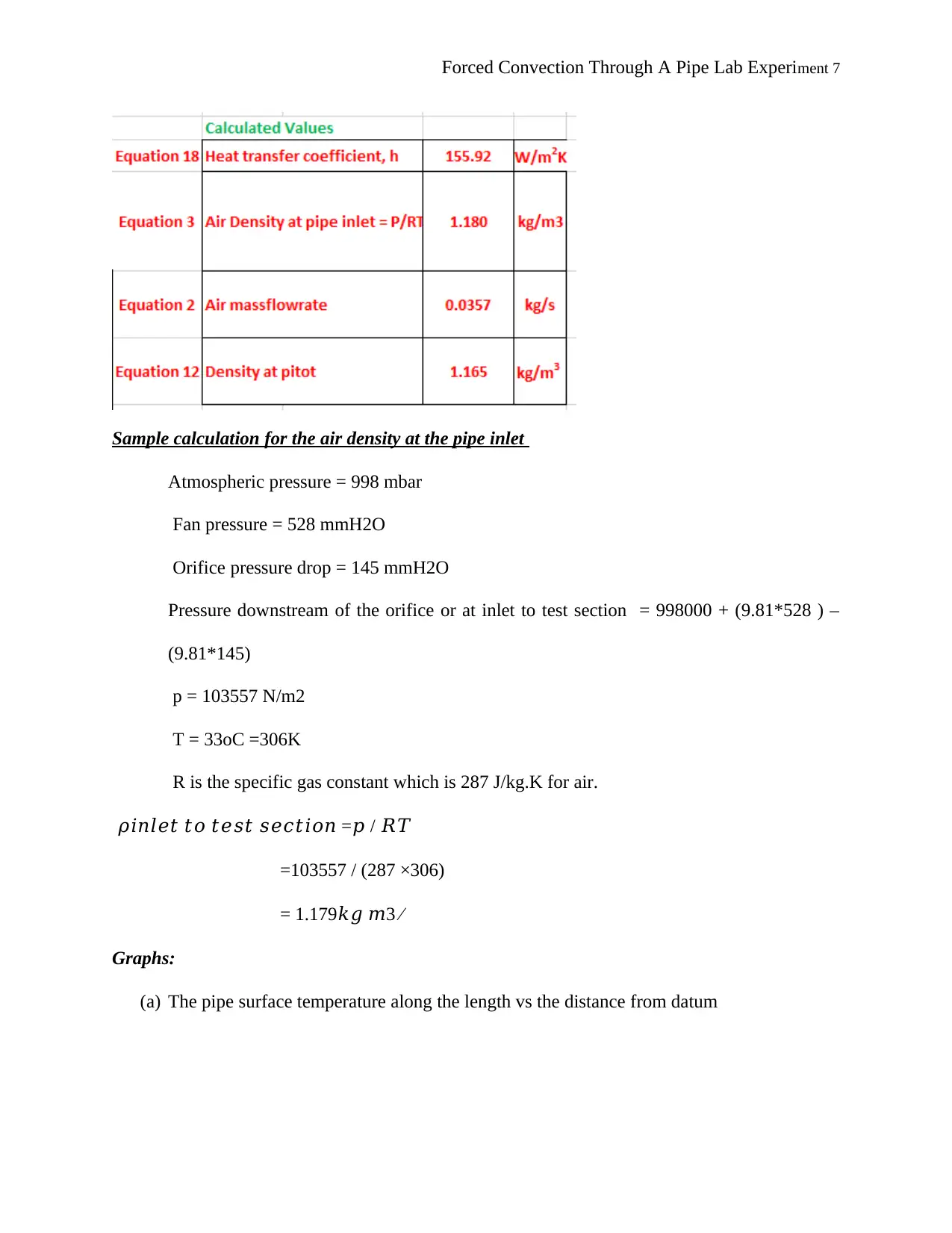
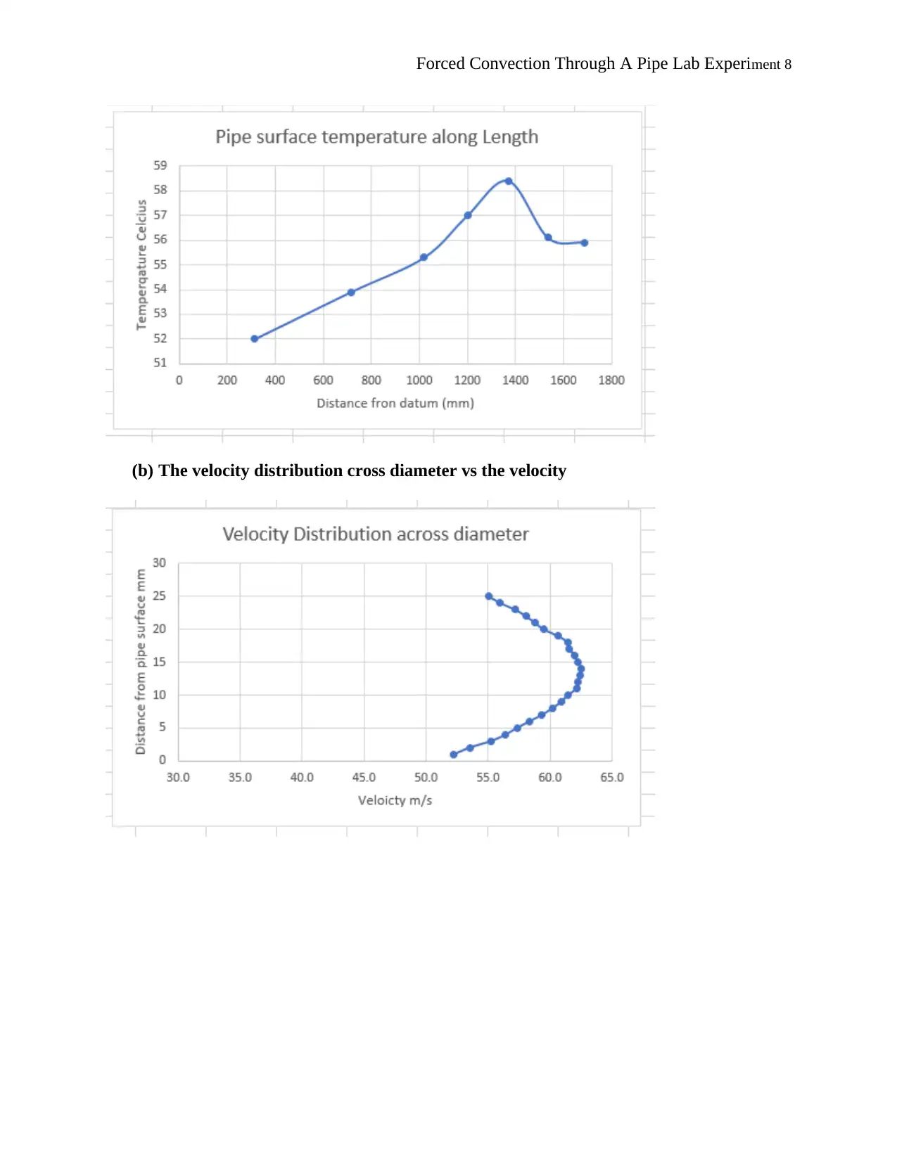
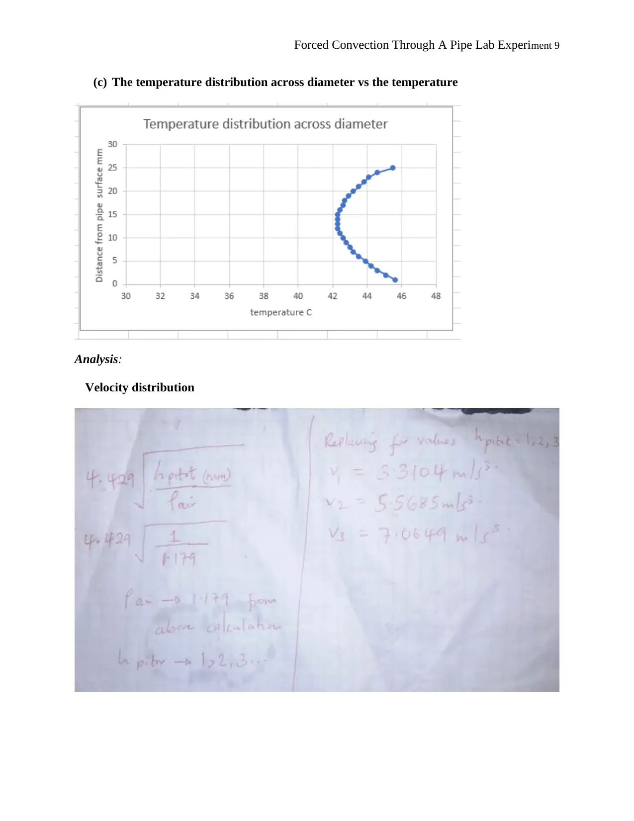
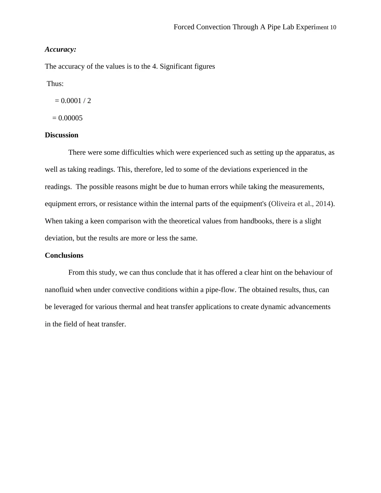
This lab report details an experiment on forced convection through a pipe. The introduction highlights the importance of heat transfer in industrial applications and the need for heat exchangers. The experiment aims to determine the convective heat transfer coefficient, velocity, and temperature distribution of air flowing through a pipe. The theoretical background, based on Newton's law of cooling, is provided. The report describes the apparatus, including the TD1 Forced Convection Heat Transfer apparatus, Pitot tube, and thermocouples. The test procedure involves varying airspeed, setting voltage, and recording readings. Results include tabulated experimental data and calculated results, such as air density. Graphs illustrate pipe surface temperature and velocity/temperature distributions. The discussion addresses experimental difficulties and potential deviations from theoretical values. The conclusion summarizes the findings and their implications for thermal and heat transfer applications. A comprehensive list of cited works is included.

Forced Convection Through A Pipe Lab Experiment 1
FORCED CONVECTION THROUGH A PIPE LAB EXPERIMENT
Name of Student
Institution
Date
FORCED CONVECTION THROUGH A PIPE LAB EXPERIMENT
Name of Student
Institution
Date
Paraphrase This Document
Need a fresh take? Get an instant paraphrase of this document with our AI Paraphraser

Forced Convection Through A Pipe Lab Experiment 2
Introduction
Heat is one of the major products which is generated in industries as well as industrial
plant facilities. The heat which is generated can be used for several applications including
moulding, casting among others. However, the heat generated results into increased temperature,
thereby putting most of the equipment into jeopardy (Achenbach, 2013). Hence, the need for
heat exchangers which are responsible for the provision of energy change. In this experiment, the
investigation focus on a pipe; which aims at determining the convective heat transfer coefficient
for forced convection for air that is flowing through it, as well as determining the velocity and
temperature distribution through the pipe.
Theory
Considering the figure below:
Figure 1 Temperature and velocity profiles developed during forced convection.

Forced Convection Through A Pipe Lab Experiment 3
Energy gets transferred from the heated surface to the fluid as it passes through it due to forced
convection. This energy can be determined through the newton's law of cooling below.
β¦β¦β¦β¦β¦β¦β¦β¦β¦β¦Eqn (1)
Where;
h is the convective heat transfer coefficient (W/m2.K)
Ts is the pipe surface temperature (oC),
TΞ± is the fluid average temperature (oC) (Ahmed and Yovanovich, 2015)
Description of Apparatus
Forced convection heat transfer apparatus used in the experiment
There are many types of equipment which are utilized for the experiment. These include:
β This is a preview!β
Do you want full access?
Subscribe today to unlock all pages.

Trusted by 1+ million students worldwide

Forced Convection Through A Pipe Lab Experiment 4
ο TD1 Forced Convection Heat Transfer apparatus- this apparatus allows for the evaluation
of the theory.
ο Pitot measuring tube- this is a unit located in a measuring apparatus which enables the
determination of temperature profiles as well as the velocity through the pipe (Akpinar
and Toraman, 2016)
ο A u-shaped pipe- this is used to link the heated copper and the smaller diameter pipe.
ο A thermometer- used for the determination of the temperature in the test tube
ο Thermocouples- used in the determination of a variety of temperature along the pipe
ο Digital indicator- used for the display of the readings within the thermocouple (Churchill
and Bernstein, 2013).
The diagram below shows the general layout of the apparatus
Test Procedure
Paraphrase This Document
Need a fresh take? Get an instant paraphrase of this document with our AI Paraphraser

Forced Convection Through A Pipe Lab Experiment 5
The position of the plate located above the fan inlet was varied to adjust the airspeed. The
initial test was then conducted, having the plate fully open. The fan was then started. While air
flows the rough the pipe, the voltage was set slowly till it reaches 150volts. The unit was then
run for 18 minutes till an equilibrium temperature was obtained by the help of a thermocouple 5.
Readings from the manometers were then recorded and tabulated below. The Pitot tube was then
set against the duct and then thermocouple 14 selected. The pitot was then traversed and results
tabulated. After the process was done, the heater was then turned off and allowed to cool for five
minutes.
Results
Table 1: Initial experimental data taken once thermal equilibrium is reached.
Table 2. Temperature measurements data taken once thermal equilibrium is reached.

Forced Convection Through A Pipe Lab Experiment 6
Table 3. Temperature measurements data taken once thermal equilibrium is reached.
Calculated Results:
Table 3. Temperature measurements data taken once thermal equilibrium is reached.
Calculated Results:
β This is a preview!β
Do you want full access?
Subscribe today to unlock all pages.

Trusted by 1+ million students worldwide

Forced Convection Through A Pipe Lab Experiment 7
Sample calculation for the air density at the pipe inlet
Atmospheric pressure = 998 mbar
Fan pressure = 528 mmH2O
Orifice pressure drop = 145 mmH2O
Pressure downstream of the orifice or at inlet to test section = 998000 + (9.81*528 ) β
(9.81*145)
p = 103557 N/m2
T = 33oC =306K
R is the specific gas constant which is 287 J/kg.K for air.
ππππππ‘ π‘π π‘ππ π‘ π πππ‘πππ =π / π π
=103557 / (287 Γ306)
= 1.179ππ π3 β
Graphs:
(a) The pipe surface temperature along the length vs the distance from datum
Paraphrase This Document
Need a fresh take? Get an instant paraphrase of this document with our AI Paraphraser

Forced Convection Through A Pipe Lab Experiment 8
(b) The velocity distribution cross diameter vs the velocity

Forced Convection Through A Pipe Lab Experiment 9
(c) The temperature distribution across diameter vs the temperature
Analysis:
Velocity distribution
(c) The temperature distribution across diameter vs the temperature
Analysis:
Velocity distribution
β This is a preview!β
Do you want full access?
Subscribe today to unlock all pages.

Trusted by 1+ million students worldwide

Forced Convection Through A Pipe Lab Experiment 10
Accuracy:
The accuracy of the values is to the 4. Significant figures
Thus:
= 0.0001 / 2
= 0.00005
Discussion
There were some difficulties which were experienced such as setting up the apparatus, as
well as taking readings. This, therefore, led to some of the deviations experienced in the
readings. The possible reasons might be due to human errors while taking the measurements,
equipment errors, or resistance within the internal parts of the equipment's (Oliveira et al., 2014).
When taking a keen comparison with the theoretical values from handbooks, there is a slight
deviation, but the results are more or less the same.
Conclusions
From this study, we can thus conclude that it has offered a clear hint on the behaviour of
nanofluid when under convective conditions within a pipe-flow. The obtained results, thus, can
be leveraged for various thermal and heat transfer applications to create dynamic advancements
in the field of heat transfer.
Paraphrase This Document
Need a fresh take? Get an instant paraphrase of this document with our AI Paraphraser

Forced Convection Through A Pipe Lab Experiment 11
Work Cited
Achenbach, E., 2013. The effects of surface roughness and tunnel blockage on the flow past
spheres. Journal of fluid mechanics, 65(1), pp.113-125.
Achenbach, E., 2015. Total and local heat transfer from a smooth circular cylinder in cross-flow
at high Reynolds number. International Journal of Heat and Mass Transfer, 18(12), pp.1387-
1396.
Ahmed, G.R. and Yovanovich, M.M., 2015. Approximate analytical solution of forced
convection heat transfer from isothermal spheres for all prandtl numbers. Previews of Heat and
Mass Transfer, 2(21), p.108.
Akpinar, E.K. and Toraman, S., 2016. Determination of drying kinetics and convective heat
transfer coefficients of ginger slices. Heat and Mass Transfer, 52(10), pp.2271-2281.
Aufdermaur, A.N. and Joss, J., 2017. A wind tunnel investigation on the local heat transfer from
a sphere, including the influence of turbulence and roughness. Zeitschrift fΓΌr angewandte
Mathematik und Physik ZAMP, 18(6), pp.852-866.
Churchill, S.W. and Bernstein, M., 2013. A correlating equation for forced convection from
gases and liquids to a circular cylinder in crossflow.
Gupta, A.K., Chhabra, R.P. and Suryanarayana, N.V., 2017. 3.2. 2 FORCED CONVECTION:
EXTERNAL FLOWS. CRC Handbook of Thermal Engineering.
Kumar, M., 2014. Effect of size on forced convection greenhouse drying of khoa. Journal of
Mechanical Engineering and Sciences, 7, pp.1157-1167.
Kumar, M., Khatak, P., Sahdev, R.K. and Prakash, O., 2011. The effect of open sun and indoor
forced convection on heat transfer coefficients for the drying of papad. Journal of Energy in
Southern Africa, 22(2), pp.40-46.

Forced Convection Through A Pipe Lab Experiment 12
Kurazumi, Y., Rezgals, L. and Melikov, A.K., 2014. Convective heat transfer coefficients of the
human body under forced convection from ceiling. Journal of Ergonomics, 4(1), p.1000126.
Oh, W. and Kato, S., 2018. The effect of airspeed and wind direction on human's thermal
conditions and air distribution around the body. Building and Environment, 141, pp.103-116.
Oliveira, A.V.M., Gaspar, A.R., Francisco, S.C. and Quintela, D.A., 2014. Analysis of natural
and forced convection heat losses from a thermal manikin: Comparative assessment of the static
and dynamic postures. Journal of wind engineering and industrial aerodynamics, 132, pp.66-76.
Rastogi, P. and Mahulikar, S.P., 2018. Optimization of micro-heat sink based on theory of
entropy generation in laminar forced convection. International Journal of Thermal
Sciences, 126, pp.96-104.
Silva, M.J., Zdanski, P.S.B. and Vaz Jr, M., 2017. Forced convection on grey cast iron plate-fins:
Prediction of the heat transfer coefficient. International Communications in Heat and Mass
Transfer, 81, pp.1-7.
Silva, M.J., Zdanski, P.S.B. and Vaz Jr, M., 2017. Forced convection on grey cast iron plate-fins:
Prediction of the heat transfer coefficient. International Communications in Heat and Mass
Transfer, 81, pp.1-7.
Will, J.B., Kruyt, N.P. and Venner, C.H., 2017. An experimental study of forced convective heat
transfer from smooth, solid spheres. International journal of Heat and Mass transfer, 109,
pp.1059-1067.
β This is a preview!β
Do you want full access?
Subscribe today to unlock all pages.

Trusted by 1+ million students worldwide
1 out of 12
Related Documents

Your All-in-One AI-Powered Toolkit for Academic Success.
Β +13062052269
info@desklib.com
Available 24*7 on WhatsApp / Email
Unlock your academic potential
Copyright Β© 2020β2025 A2Z Services. All Rights Reserved. Developed and managed by ZUCOL.