ME 2453 Project: Boiler Performance Improvement by Fouling Reduction
VerifiedAdded on 2023/06/11
|17
|4437
|409
Project
AI Summary
This mechanical engineering project report investigates methods to improve boiler performance by reducing heat loss caused by fouling. The report includes a literature review on fouling, research questions, aims, sub-goals, theoretical content, experimental setup, and anticipated results. The project explores the optimum operating conditions for a three-stage pirotubular boiler connected in parallel, aiming to maximize efficiency and minimize harmful emissions. The report also discusses the design and installation features of the new system, including suitability for pressurized combustion chambers, mechanical spraying systems, and automatic air controllers. The project concludes with a discussion of the potential long-term impact of the work on boiler performance and efficiency. This document is available on Desklib, a platform offering a wide range of study resources, including past papers and solved assignments, to support students' academic needs.
Running head: ENGINEERING PROJECT PREPARATION
Engineering Project Preparation
[Name of the Student]
[Name of the University]
[Author note]
Engineering Project Preparation
[Name of the Student]
[Name of the University]
[Author note]
Paraphrase This Document
Need a fresh take? Get an instant paraphrase of this document with our AI Paraphraser
1ENGINEERING PROJECT PREPARATION
Abstract
Due to the accumulation of various kind of unwanted materials inside the pipes, machines or the
heat exchanges, different kind of problem arises in the liquid bearing systems. This acts as a
major reason which interferes the function of the entire system. In this study a literature review
has been conducted regarding the boilers. Followed by a research conducted upon this and after
this aims and sub goals of the research has also been discussed. A clear theoretical basis of the
work has also been provided. Experimental set-up has also been discussed along with the
limitations as well. Followed by this the results and outcomes has also been discussed.
2ENGINEERING PROJECT PREPARATION
Table of Contents
Introduction:....................................................................................................................................3
Literature review:.............................................................................................................................3
Research Question/s, Aim & Sub-goals..........................................................................................5
Theoretical Content.........................................................................................................................6
Experimental Set Up........................................................................................................................7
Results and Findings......................................................................................................................11
Conclusion:....................................................................................................................................11
Project Planning and Gantt chart...................................................................................................12
Bibliography:.................................................................................................................................14
⊘ This is a preview!⊘
Do you want full access?
Subscribe today to unlock all pages.
Trusted by 1+ million students worldwide
3ENGINEERING PROJECT PREPARATION
Introduction:
Fouling is considered to a technical term which defines the accumulation of the unwanted
materials on the heat transfer surfaces. This type of materials are either living or non-living
substances. This is generally distinguished from the other type of phenomenon related to the
growth of the surface, which generally occurs upon the components surface, system or the
performance of a function which has been explained and useful. Besides this the fouling process
is associated with impeding or interfering with all this functions. Fouling on the boilers is
generally dependent upon the type of boiler that is being used and also upon the design and the
fuel that is being fired. The fouling is different in many ways in different type of boilers
(Ikechukwu 2014).
Despite of the various causes the actual nature of deposit consists of extra resistance in
the process of transferring heat which is generally presented which is responsible for reducing
the capability of the operations which the heat exchanger is having. Due to the accumulation of
various kind of unwanted materials inside the pipes, machines or the heat exchanges, different
kind of problem arises in the liquid bearing systems. This acts as a major reason which interferes
the function of the entire system. The fouling factor helps in determining the rate of fouling and
in this vital role is played by the temperature (Chen et al. 2012). This kind of deposition also
gives rise to different kind of difficulties in the fluid bearing system which would be having an
effect upon the total performance negatively upon the plant which initially causes a lower
production capacity along with high maintenance cost.
Paraphrase This Document
Need a fresh take? Get an instant paraphrase of this document with our AI Paraphraser
4ENGINEERING PROJECT PREPARATION
Literature review:
According to some of the investigations conducted by some of the researchers upon
fouling discusses about the various types of depositions and also the possible causes as well as
the resulting problems (Low et al. 2015). Besides this other researchers have been associated
with investigating the mechanisms and the technologies that are available for the purpose of
preventing the deposition problems in the boilers by making use of the soot blowers, ash
behavior prediction tools, and many more.
Gutierrez et al. has been associated with developing a model which is completely dynamic. The
model is prepared which is generally dependent upon the mass along with the energy and the
balances present in the momentum which is done by making use of the constitutional equations
(Ortiz 2011). Besides two parts has also been divided in the fire-tube boilers and this includes
“the fire/gas side” and “the water/steam side”. In the beginning a non-liner model has been
prepared which is followed by reducing it so as to shorten the computational time however this
has been associated with providing a reasonable result. This might be allowing the simulation of
the processes along with the design which is a multivariable controller (Li et al. 2012).
Simulations acts as a very useful tool for the training as well as for providing assistance during
online decisions (Williamson 1994).
According to Kumar et al. pressure vessels are generally associated with working under a
particular pressure as well as under a particular temperature. Besides this they also are associated
with containing lethal substances which acts as a hazardous element for both humans as well as
for animals and the entire environment (Kumar and Kumar 2014). Various kind of design codes
have prepared along with being developed for the purpose of having an assured minimal amount
of safety standards. Various type of calculations can be applied to the software for the purpose of
5ENGINEERING PROJECT PREPARATION
finishing the design of the pressure vessel as quickly as possible. The study has been associated
with investigating a particular section of the parameters design. Besides there also exists several
other parameters which are not generally considered and this mainly includes the “wind loads”,
“thermal loads”, “fabrication methods”, “erection load”, “seismic load”, “transportation load”
and and many more (Lawrence et al. 2008). But despite of all this overcoming of the
insufficiency can be achieved by the process of mastering software. Use of the graphical based
software has been done for the purpose of making the Mechanical design of pressure vessel.
According to Ganan et al. the installation of thermal power are associated with emitting
different types of matter which are responsible for polluting the atmosphere which acts as the
main reason lying behind the greenhouse effect and is also responsible for harming the entire
environment. The major pollutants which are emitted to the atmosphere due to the use of these
equipment mainly includes the Sulphur Oxide (SO2), Hydrocarbon (HC), Carbon monoxide
(CO), Carbon dioxide (CO2), and Nitrogen Oxides (NOx). Because of high pollution due to all
these type of gases, various agencies responsible for looking after the environment have been
associated with imposing certain maximum levels of emission (Ganan et al. 2005). There exists
an origin of each pollutants which has been emitted in the resulting gases during the process of
combustion. From the combustion of the gases three fundamental elements can be found and this
includes the “fuel”, “comburent” and “activation energy”.
Research Question/s, Aim & Sub-goals
The research questions that this paper tries to answer mainly includes the following:
Q1. How can Fouling be reduced?
Q2. What are the general materials required for eliminating the fouling effect?
⊘ This is a preview!⊘
Do you want full access?
Subscribe today to unlock all pages.
Trusted by 1+ million students worldwide
6ENGINEERING PROJECT PREPARATION
Q3. How the efficiency of the boilers can be increase?
In this research the optimum operating conditions are to be evaluated of the two three-
stage pirotubular boiler which are to be connected parallel by making use of the gasoil C. The
main of this research is to develop the entire system by considering the operating variables which
are generally present in the injection pressure and the number of burners that are to be used.
The main goal of this research is to reach the highest level of efficiency by studying the
optimal operating conditions that the three-stage pirotubular boiler is having. Another goal of
this work includes the least amount emissions from the boiler which are harmful to the
environment. The operations of the boiler are to be analysed by means of altering the variables
which are generally allowed during the process of installation and this mainly includes the
pressure related to injection and the number of burners that are to be used, besides this it is also
to be noted that both of this are responsible for modifying the flow of mass independently.
Theoretical Content
Fire-tube boiler are generally considered to be a boiler in which the gases which are hot
comes from the burner passes through single or multiple tubes and are generally responsible for
running through the water containers which are sealed. Followed by this the heat of the gases is
transferred through the walls of the tubes which is generally done by the process of thermal
conduction, which initially leads to the heating of the water and this initially creates a steam
(Hansen and Blankinship 2006). The fire-tube boiler are generally associated with developing
one third of the four major historical types of boilers which mainly includes the “low-pressure
tank“, “flued boilers with one or two large flues”, "haystack" boilers, “fire-tube boilers with
many small tubes”, and “high-pressure water-tube boilers”. The cylindrical tank that is to be used
Paraphrase This Document
Need a fresh take? Get an instant paraphrase of this document with our AI Paraphraser
7ENGINEERING PROJECT PREPARATION
might be horizontal or vertical in shape. A conceptual physical geometry needs to be developed
for the process of designing the fire-tube steam boiler along with making necessary calculations
and from this the dimensions and other deductions can also be estimated, and lastly, there is a
need of developing a working drawing, which is associated with analyzing with software
(Wacławiak and Kalisz 2012). There are several researchers who are associated with working on
the fire tube boiler and also on the efficiency.
Experimental Set Up
The experiment would be consisting of two three-stage peritubular boiler having the
thermal power of 465 KW. This includes the mono-block boilers which are generally made by
making use of the foils made of steel and are generally isolated by making use of the fiber glass
having the thickness of around 70mm. the boilers would be equipped with a control panel which
would be having two thermostats. This thermostats are associated with regulating the working tie
for each of the burner for the gasoil C which would be having the maximum viscosity of around
6cSt to 20 0C. Along with this there would be existing two time counters which would be
associated with registering the number of operating ours for each of the burner (Mahajan, Patil
and Attarde 2018). For the purpose of handling the system in case of failure of the one system
there exists a temperature gauge and a pressure gauges along with a safety thermostat.
The features that the installation process of the new system have been listed below:
This would be suitable for operating with the pressurized as well as with the negative
pressure combustion chambers.
Would be consisting a mechanical spraying system which is having high-pressure.
8ENGINEERING PROJECT PREPARATION
Would be having an automatic combustion chamber purge prior to the lighting of the
boiler.
There would be a control panel that which would associated with displaying the
operations of the burner.
Presence of an automatic air controller at each and every stage.
The air would be controlled by making use of the hydraulic system which would be
associated with allowing of the purging of the burner by having an open and closed air
condition. This would be mainly done during the periods when no firing takes place and
this generally done so as to prevent the entry of air in the combustion chamber (Dai et al.
2015).
All this boilers are connected parallel by making use of a circuit which is having a closed
nature and in this the circulation of water takes place through the pressure of working and this
varies from 1.5 to 2.0 kg/cm2. The safety valve would be adjusted to a value of around 3kg/cm2.
The operations of this boilers are semi-automatic and would be having the capability of
regulating the air for each and every level of the power. All this regulations would be conducted
by making use of the hydraulic system which is turn is associated with allowing the blocking of
the supply of air during the halting phase (Hare, Rasul and Moazzem, 2010). Besides this it
would also be responsible for the pre-evacuation of the gases which are present in the channels
and this would be done before the ignition takes place. Initially this would be associated with
facilitating the start-ups due to the fact that the combustion process becomes rich in oxygen.
The operations of the combustion chamber generally occurs in the partial vacuum and
due to this reason after the initiation of the combustion process the whole process would be
leading to the expelling of the gases in its own atmospheric pressure (Patiño et al. 2016). Along
⊘ This is a preview!⊘
Do you want full access?
Subscribe today to unlock all pages.
Trusted by 1+ million students worldwide
9ENGINEERING PROJECT PREPARATION
with this the circuit of the gas would be consisting of three phases amongst which two would be
present in the fire place and the other one would be present in the exhaust tubes. Along with this
circuit would be would be consisting of a tubular bunch where it is seen that the fumes are
associated with circulating in the turbulent flow. This in tur enhances the transmission of heat.
There exists a horizontal exit in the plenum chamber which is associated with facilitating the
cleaning of the tubular sheaf along with the combustion chamber (Ohijeagbon et al. 2013). For
the purpose of making estimations related to the installation of efficiency, the composition of the
fumes was determined in relation to the “air excess coefficient” (λ) , “the losses for unburned
gases in the exhaust fumes” (qi), “the losses for the sensible enthalpy” (qA), and lastly the
“temperature of the exit” (TH). All this data would be gathered by making use of the TESTCO
mode 300 M-I analyzer. The probe of this analyzer was placed in the exit fumes from the boiler
(Dai et al. 2015). The equations provided below shows the different way by which the various
parameters can be calculated.
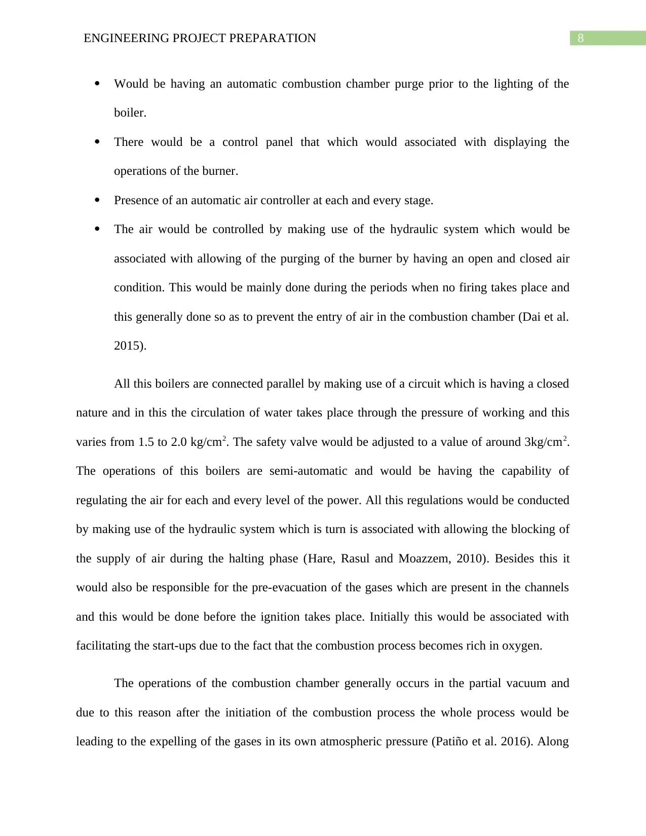
Equation 1:
In the (CO2) Max is generally considered to be the specific rate that is maximum and has
the capability of getting liberated, and the number 21 represents the oxygen percentage in the air
and the O2 is generally considered to be the value of oxygen.
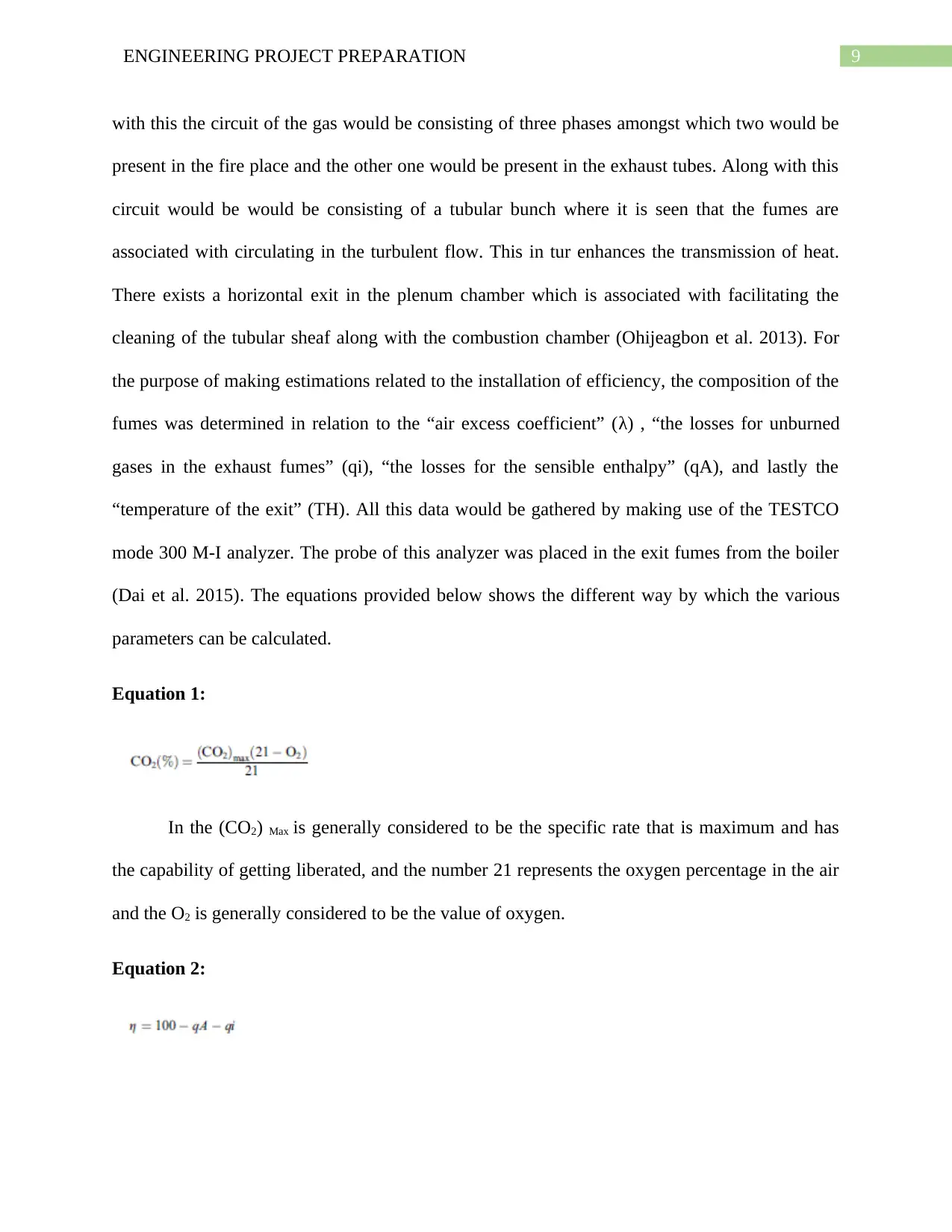
Equation 2:
with this the circuit of the gas would be consisting of three phases amongst which two would be
present in the fire place and the other one would be present in the exhaust tubes. Along with this
circuit would be would be consisting of a tubular bunch where it is seen that the fumes are
associated with circulating in the turbulent flow. This in tur enhances the transmission of heat.
There exists a horizontal exit in the plenum chamber which is associated with facilitating the
cleaning of the tubular sheaf along with the combustion chamber (Ohijeagbon et al. 2013). For
the purpose of making estimations related to the installation of efficiency, the composition of the
fumes was determined in relation to the “air excess coefficient” (λ) , “the losses for unburned
gases in the exhaust fumes” (qi), “the losses for the sensible enthalpy” (qA), and lastly the
“temperature of the exit” (TH). All this data would be gathered by making use of the TESTCO
mode 300 M-I analyzer. The probe of this analyzer was placed in the exit fumes from the boiler
(Dai et al. 2015). The equations provided below shows the different way by which the various
parameters can be calculated.
Equation 1:
In the (CO2) Max is generally considered to be the specific rate that is maximum and has
the capability of getting liberated, and the number 21 represents the oxygen percentage in the air
and the O2 is generally considered to be the value of oxygen.
Equation 2:
Paraphrase This Document
Need a fresh take? Get an instant paraphrase of this document with our AI Paraphraser
10ENGINEERING PROJECT PREPARATION
The combustion process’s efficiency is generally dependent upon the decrease that the
heating fuel is having which has been estimated.
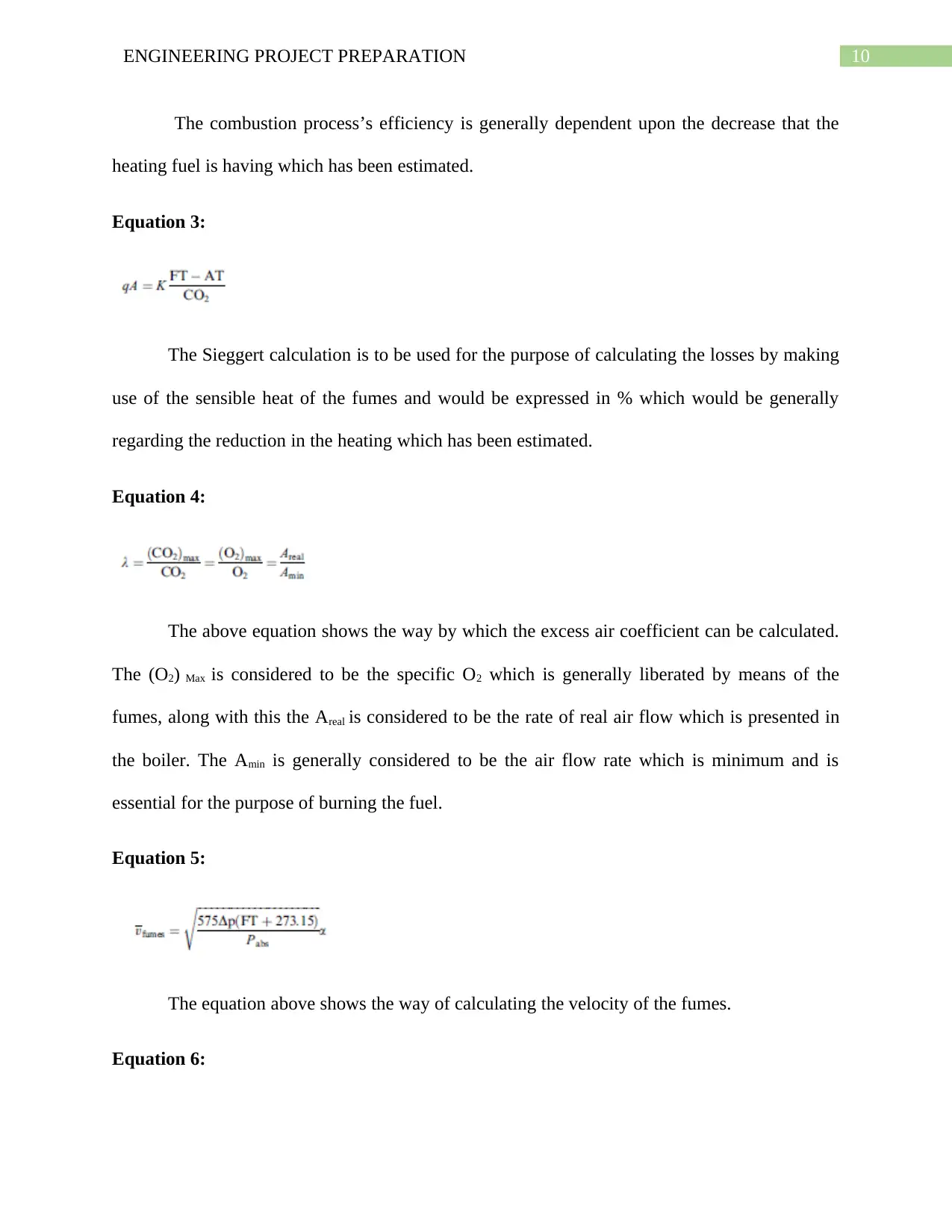
Equation 3:
The Sieggert calculation is to be used for the purpose of calculating the losses by making
use of the sensible heat of the fumes and would be expressed in % which would be generally
regarding the reduction in the heating which has been estimated.
Equation 4:
The above equation shows the way by which the excess air coefficient can be calculated.
The (O2) Max is considered to be the specific O2 which is generally liberated by means of the
fumes, along with this the Areal is considered to be the rate of real air flow which is presented in
the boiler. The Amin is generally considered to be the air flow rate which is minimum and is
essential for the purpose of burning the fuel.
Equation 5:
The equation above shows the way of calculating the velocity of the fumes.
Equation 6:
The combustion process’s efficiency is generally dependent upon the decrease that the
heating fuel is having which has been estimated.
Equation 3:
The Sieggert calculation is to be used for the purpose of calculating the losses by making
use of the sensible heat of the fumes and would be expressed in % which would be generally
regarding the reduction in the heating which has been estimated.
Equation 4:
The above equation shows the way by which the excess air coefficient can be calculated.
The (O2) Max is considered to be the specific O2 which is generally liberated by means of the
fumes, along with this the Areal is considered to be the rate of real air flow which is presented in
the boiler. The Amin is generally considered to be the air flow rate which is minimum and is
essential for the purpose of burning the fuel.
Equation 5:
The equation above shows the way of calculating the velocity of the fumes.
Equation 6:
11ENGINEERING PROJECT PREPARATION
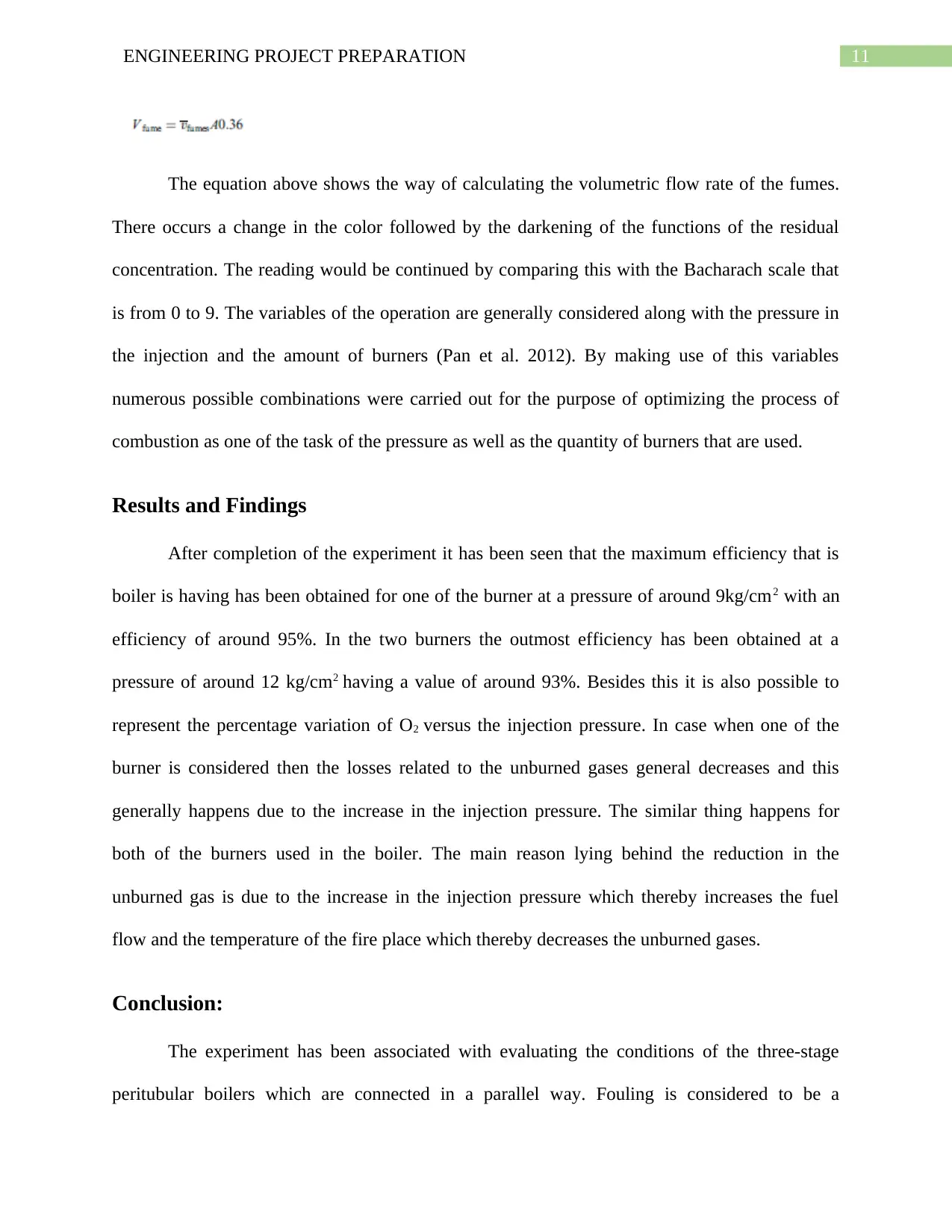
The equation above shows the way of calculating the volumetric flow rate of the fumes.
There occurs a change in the color followed by the darkening of the functions of the residual
concentration. The reading would be continued by comparing this with the Bacharach scale that
is from 0 to 9. The variables of the operation are generally considered along with the pressure in
the injection and the amount of burners (Pan et al. 2012). By making use of this variables
numerous possible combinations were carried out for the purpose of optimizing the process of
combustion as one of the task of the pressure as well as the quantity of burners that are used.
Results and Findings
After completion of the experiment it has been seen that the maximum efficiency that is
boiler is having has been obtained for one of the burner at a pressure of around 9kg/cm2 with an
efficiency of around 95%. In the two burners the outmost efficiency has been obtained at a
pressure of around 12 kg/cm2 having a value of around 93%. Besides this it is also possible to
represent the percentage variation of O2 versus the injection pressure. In case when one of the
burner is considered then the losses related to the unburned gases general decreases and this
generally happens due to the increase in the injection pressure. The similar thing happens for
both of the burners used in the boiler. The main reason lying behind the reduction in the
unburned gas is due to the increase in the injection pressure which thereby increases the fuel
flow and the temperature of the fire place which thereby decreases the unburned gases.
Conclusion:
The experiment has been associated with evaluating the conditions of the three-stage
peritubular boilers which are connected in a parallel way. Fouling is considered to be a
⊘ This is a preview!⊘
Do you want full access?
Subscribe today to unlock all pages.
Trusted by 1+ million students worldwide
1 out of 17
Related Documents


Your All-in-One AI-Powered Toolkit for Academic Success.
+13062052269
info@desklib.com
Available 24*7 on WhatsApp / Email
![[object Object]](/_next/static/media/star-bottom.7253800d.svg)
Unlock your academic potential
Copyright © 2020–2026 A2Z Services. All Rights Reserved. Developed and managed by ZUCOL.