Foundation Networks Assignment 2 Solutions - Electrical Engineering

Verified

Added on  2022/10/02

|6
|1096
|348
Homework Assignment
AI Summary
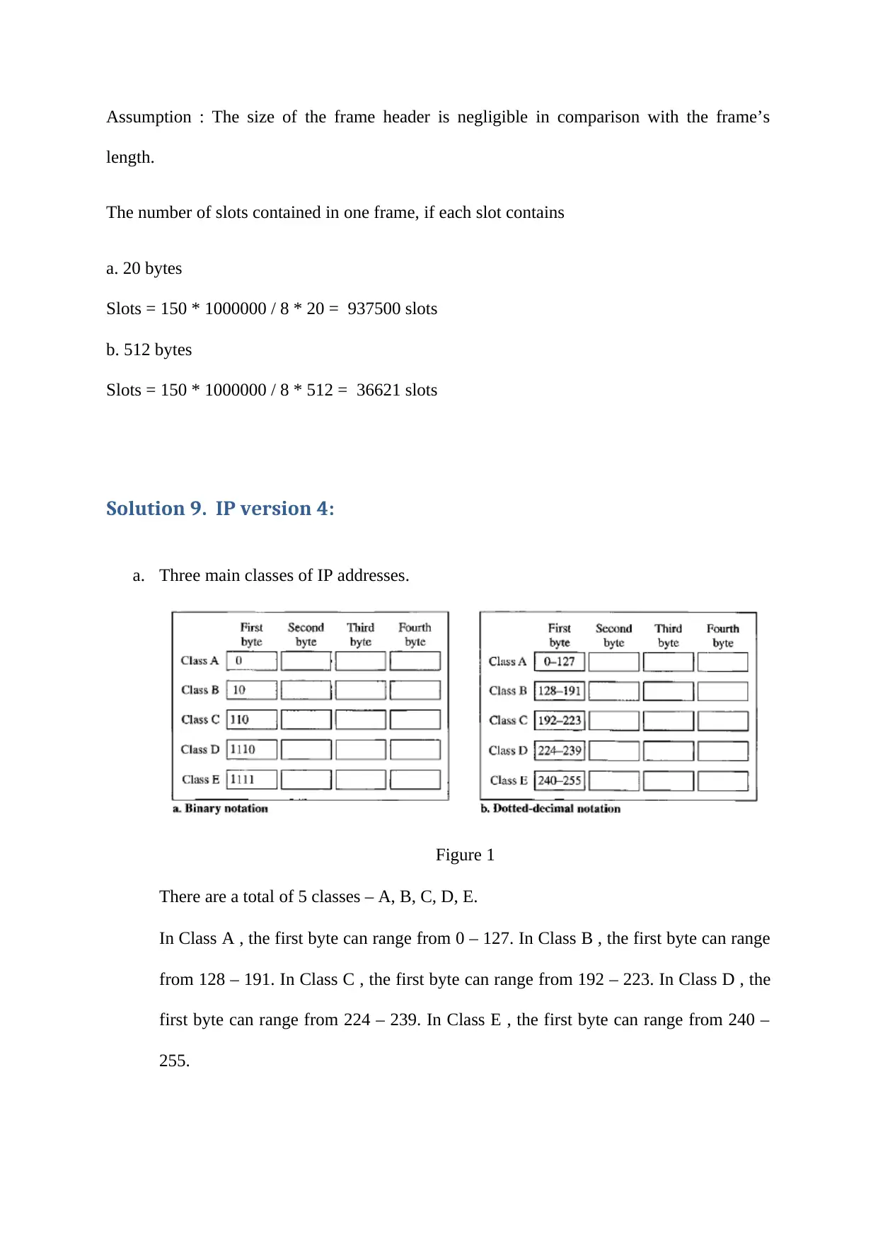
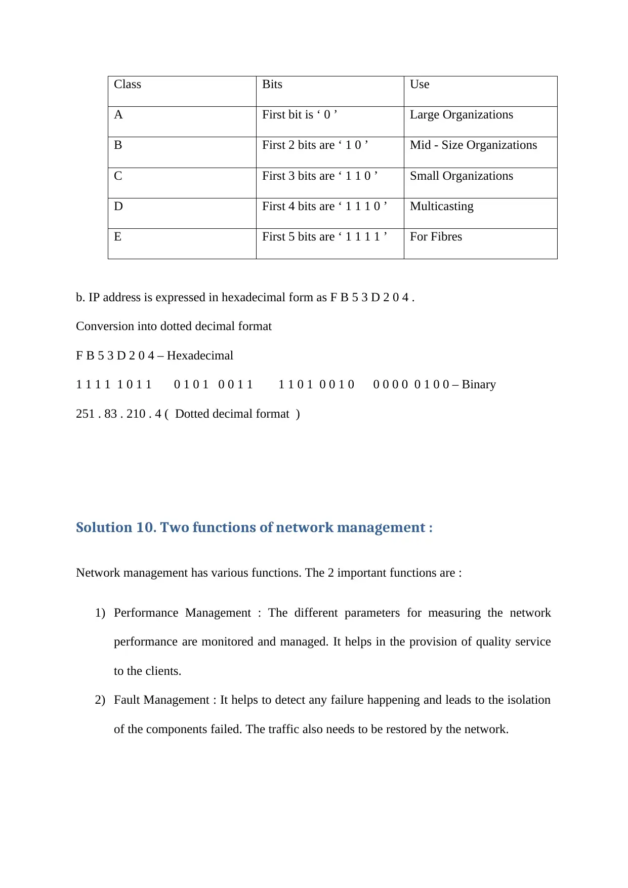
This document provides comprehensive solutions to Foundation Networks Assignment 2. The solutions cover a range of topics including point-to-point links, ARQ strategies, throughput and link efficiency calculations, bit error rates, the p-persistence algorithm, CSMA/CD networks, frame length and transmission calculations, the 5-4-3 rule, IEEE 802.3 and other frame standards, DQDB bus operation, IP version 4 addressing (classes, hexadecimal conversion), and network management functions such as performance and fault management. The solutions are detailed, showing step-by-step calculations and explanations for each problem. The document is designed to aid students in understanding and solving networking problems, providing a valuable resource for their studies in electrical engineering and related fields. It includes calculations and explanations to help students learn and solve similar problems.
Document Page
Networking
Foundation Networks
Student Name –
Student ID -
tabler-icon-diamond-filled.svg

Paraphrase This Document

Need a fresh take? Get an instant paraphrase of this document with our AI Paraphraser
Document Page
Solution 1.
A point – to - point link is operating at 10 kbps uses a stop – and - wait ARQ strategy. The
link has a propagation delay of 25ms and a total processing delay of 15ms. Data is
transmitted using a frame size of 898 bytes of which 870 bytes contain information. The
acknowledgements contain 8 bytes.
Throughput = ? = Tt x B / ( Tt + 2 Tp ) = 15 x 10 kbps / ( 15 + 2 * 25 ) = 2.3 kbps
Link efficiency = ? = ( 2.3 / 10 ) * 100 = 0.23 = 23 %
The throughput is 2.3 kbps. The link efficiency is 23 %.
Solution 2.
A frame of data of length 512 bytes is transmitted over a link with a bit error rate of 10−4.
Probability that a frame will be received erroneously = ? = 512 * 8 * 10 − 4 = 0 . 4096
The required probability is 0.4096.
Solution 3.
Explanation : The P - persistence algorithm used with CSMA / CD networks attempts to
improve bus efficiency compared with 1 - persistence and non - persistence algorithms .
The p – persistence algorithm merges the various benefits of 1 - persistence and non-
persistence algorithms. The algorithm helps in the reduction of the number of collisions
Document Page
occurring in comparison with the 1 - persistence CSMA. As compared to the non –
persistence CSMA, the channel utilization is good in this algorithm. In this algorithm, if a
transmission station wants to send a frame and finds that the channel is busy, then it will wait
till the transmission ends. After this happens, it transmits the frame having the probability ‘ p
’.
Solution 4.
A CSMA / CD - based LAN operates at 100 Mbps with a utilization of 40 %.
a. The number of information bits transmitted per second = ? = 0.6 * 100 = 60 Mbits
b. The frame length is 800 bytes of which 750 convey data
The number of frame transmitted within 4 second = ? = 60 Mbits * 4 / 800 * 8 = 37500
Solution 5. “ 5 – 4 - 3 Rule ”
This rule is used for dividing the network. It states that there can be maximum 5 segments
present between 2 given nodes in a network. They can be connected by 4 repeaters /
concentrators. Out of the 5 segments , only 3 segments can have user connections. The rule is
a design method for the Ethernet computer network ( IEEE way ).
Document Page
Solution 6.
IEEE 802.3 frames contain a pad and length field, while IEEE 802.4 and 5 token-based
frames contain an ED ( End – of - frame Delimiter ) field only.
The standard 802 . 3 is Ethernet , 802 . 4 is Token Bus and 802 . 5 is Token Ring. 802 . 4 has
a more deterministic nature than 802 . 3. But if the token is lost, there can be uncertainty. In
802 . 3, pad field checks if the frame satisfies minimum length criteria. It helps in the
detection of any collision. The length field gives length of data field. In 802 . 4, end delimiter
denotes end of frame and gives the position of frame check sequence field. In 802 . 5, ending
delimiter helps in identifying end of the frame. It can also identify if it is last frame or not
( for multi frame case ).
Solution 7.
A frame comprising 512 bits is transmitted at 1 Gbps.
Maximum network span = ? = 512 bits / 1 Gbps = 0.512 micro second
Velocity of propagation is 200,000 km / s.
Network span = ? = 200,000 km / s * 0.512 micro second = 0.2 * 512 m = 102.4 m
Solution 8.
A DQDB bus operates at 150 Mbps.
tabler-icon-diamond-filled.svg

Paraphrase This Document

Need a fresh take? Get an instant paraphrase of this document with our AI Paraphraser
Document Page
Assumption : The size of the frame header is negligible in comparison with the frame’s
length.
The number of slots contained in one frame, if each slot contains
a. 20 bytes
Slots = 150 * 1000000 / 8 * 20 = 937500 slots
b. 512 bytes
Slots = 150 * 1000000 / 8 * 512 = 36621 slots
Solution 9. IP version 4:
a. Three main classes of IP addresses.
Figure 1
There are a total of 5 classes – A, B, C, D, E.
In Class A , the first byte can range from 0 – 127. In Class B , the first byte can range
from 128 – 191. In Class C , the first byte can range from 192 – 223. In Class D , the
first byte can range from 224 – 239. In Class E , the first byte can range from 240 –
255.
Document Page
Class Bits Use
A First bit is ‘ 0 ’ Large Organizations
B First 2 bits are ‘ 1 0 ’ Mid - Size Organizations
C First 3 bits are ‘ 1 1 0 ’ Small Organizations
D First 4 bits are ‘ 1 1 1 0 ’ Multicasting
E First 5 bits are ‘ 1 1 1 1 ’ For Fibres
b. IP address is expressed in hexadecimal form as F B 5 3 D 2 0 4 .
Conversion into dotted decimal format
F B 5 3 D 2 0 4 – Hexadecimal
1 1 1 1 1 0 1 1 0 1 0 1 0 0 1 1 1 1 0 1 0 0 1 0 0 0 0 0 0 1 0 0 – Binary
251 . 83 . 210 . 4 ( Dotted decimal format )
Solution 10. Two functions of network management :
Network management has various functions. The 2 important functions are :
1) Performance Management : The different parameters for measuring the network
performance are monitored and managed. It helps in the provision of quality service
to the clients.
2) Fault Management : It helps to detect any failure happening and leads to the isolation
of the components failed. The traffic also needs to be restored by the network.
chevron_up_icon
1 out of 6
circle_padding
hide_on_mobile
zoom_out_icon
[object Object]