Developing Numerical Fracture Mechanics Methodology Report, CE2
VerifiedAdded on 2020/05/08
|8
|1615
|110
Report
AI Summary
This report details a competency demonstration (Career Episode 2) focused on developing a numerical fracture mechanics methodology to calculate the life of an engine structure. The project, conducted at GE Aircraft Engine in Bangalore, India, from January 2002 to January 2004, involved improving the life of engine structural elements using a displacement control method for thermal loading. The report outlines the project's objectives, which included developing a numerical methodology for stress intensity factor calculation using ANSYS FEM software, calculating the stress intensity factor under thermal cyclic loads, and calculating fatigue crack propagation using Paris's law. The author's responsibilities included designing engine parts, performing numerical analysis, and collaborating with engineers in the USA. The project addressed the limitations of traditional load control methods by implementing a displacement control approach for a more accurate prediction of stress intensity factors, leading to improved fatigue life analysis. The report highlights challenges such as the need for expertise in validating the new methodology and details the solutions implemented, including mentorship and the application of ANSYS for numerical calculations. The project resulted in the development of a "1st time right" design, and the author was recognized by the management for the best-in-class prediction methodology.
COMPETENCY
DEMONSTRATION REPORT
Career Episode 2
HIRANMAY DASH
DEMONSTRATION REPORT
Career Episode 2
HIRANMAY DASH
Paraphrase This Document
Need a fresh take? Get an instant paraphrase of this document with our AI Paraphraser
CE 2.1 Project Information
Name of the project: Developing numerical facture mechanics methodology to calculate
the life of Engine structure
Location of the project: Bangalore, India
Project Duration: January 2002 to January 2004
Organization: GE Aircraft Engine
Role and Designation during the time: Individual contributor
CE 2.2 Project Background
CE 2.2.1 Characteristics of the project
GE aviation can be said to be one of the subsidiary of the General Electric with its
headquarters in Evendale, Ohio. The company has been able to maintain business for over 100
years. The company has been one of the largest supplier of aircraft engine and has been able to
provide engines for most of the commercial aircraft manufactures. The major competitors of the
company are Rolls-Royce and Pratt & Whitney. The company specializes in the development
and research in the field of aircraft engine. I was employed in the company for the understanding
of the designing and manufacturing process being followed by the company for the development
of their aircraft engines. For this project I had worked on the process of improvement of the life
of Engine structural Element using displacement control method for thermal loading.
CE 2.2.2 Objectives developed for the project
For the completion of the project I had set out the following objectives for the completion
of the project as per the requirements of the client:
To improve the life of Engine Structural Element using displacement control method
for thermal loading
To develop a numerical methodology for the calculation of the stress intensity factor
with the help of ANSYS FEM software.
To calculate the stress intensity factor on thermal cyclic load using numerical method
To calculate the Fatigue Crack propagation with the help of Paris’s law
CE 2.2.3 My area of work
For this project I had worked on the process of developing a methodology for the
improvement of the life of an engine being developed. The engines structural element has been
analysed with the help of the FEM using the displacement control method for the thermal
loading mechanism. All the technical tasks related to the completion of the work had been
considered and completed. I had worked on the numerical methodology for the calculation of the
stress intensity factor with the help of ANSYS. I had also worked on the calculation of the stress
intensity factor on the thermal cyclic load for the completion of the work as per the requirements.
I had also worked on the Fatigue Crack propagation calculation using Paris’s law. I had also
worked on the implementation of the finite element method for the better understanding of the
crack propagation.
⊘ This is a preview!⊘
Do you want full access?
Subscribe today to unlock all pages.

Trusted by 1+ million students worldwide
CE 2.2.4 Project Group
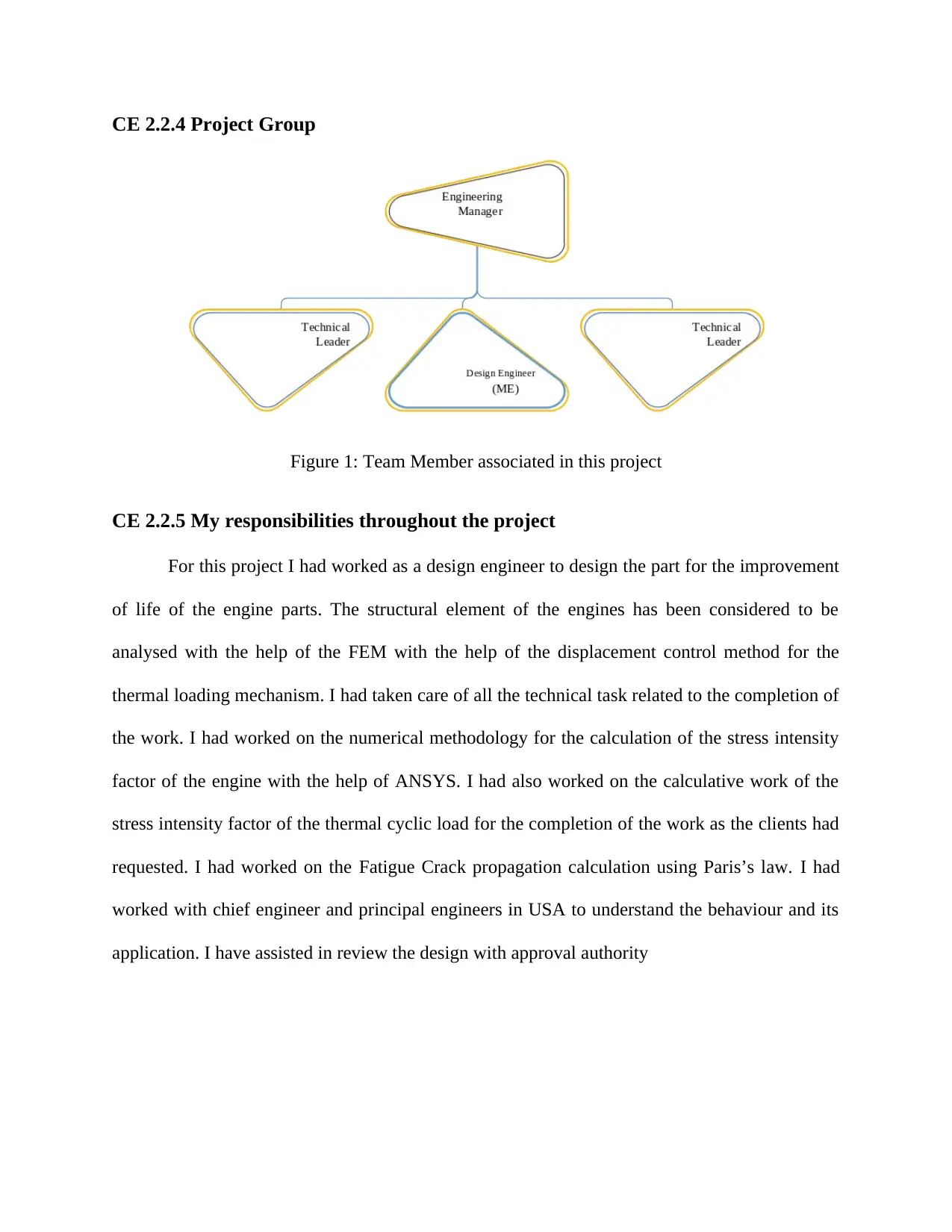
Figure 1: Team Member associated in this project
CE 2.2.5 My responsibilities throughout the project
For this project I had worked as a design engineer to design the part for the improvement
of life of the engine parts. The structural element of the engines has been considered to be
analysed with the help of the FEM with the help of the displacement control method for the
thermal loading mechanism. I had taken care of all the technical task related to the completion of
the work. I had worked on the numerical methodology for the calculation of the stress intensity
factor of the engine with the help of ANSYS. I had also worked on the calculative work of the
stress intensity factor of the thermal cyclic load for the completion of the work as the clients had
requested. I had worked on the Fatigue Crack propagation calculation using Paris’s law. I had
worked with chief engineer and principal engineers in USA to understand the behaviour and its
application. I have assisted in review the design with approval authority
Paraphrase This Document
Need a fresh take? Get an instant paraphrase of this document with our AI Paraphraser
CE 2.3 Distinctive Activity
CE 2.3.1 Comprehending the theory of the project
The major development of the company is in the field of aircraft engines for commercial
plane manufacturers. The development of an aircraft engine requires a lot technical specification
to be followed by the company. There is a lot of process which needs to be followed for the
engine development to make sure that it is stable enough to sustain load of the flight, efficient
and reliable. This is the main reason I was asked to work with the company for the understanding
of the process of calculation of the stress intensity factor for structural component of the engine.
Thus, I had proposed the main calculation of the stress intensity factor using the displacement
control method for the engine instead of load control for accurate prediction.
CE 2.3.2 Engineering knowledge and skills applied in the project
I had used my knowledge base of design engineer for the completion of the project. I had
implemented the process of calculation of numerical methodology for the finding of the stress
intensity factor with the help of ANSYS. I had also used my knowledge on fracture mechanics to
implement the fatigue crack propagation calculation with the help of Paris’s Law. I had also
implemented the finite element method to find the correct design solution.
CE 2.3.3 Accomplishment and task performed
After studying the complete engine design requirements, I was able to find the drawbacks
and the flaws in the facture mechanics calculation methodology. I had then studied the findings
with different journals and research papers to find what would be able to be implemented in to
the system so that the requirement can be easily changed to meet the final outcome of the project.
I had used the process of development of numerical methodology for the calculation of the stress
intensity factor with the help of ANSYS and used them to evaluate the life of the parts. Apart
from this I had written the daily progress report of the project and shared it with the engineering
manager to let them know about the progress of the work that had been completed in the project.
After the completion of the project I had compiled the complete the documentation of the project
and submitted it to the manager and the chief engineer’s office.
CE 2.3.4 Identified issues and their solutions
2.3.4.1 Issues
The primary issue which I had faced during the process of implementation of the new
methodology was the unavailability of the expertise for the validation of the stress intensity
factor thru new method. I had requested the manager to provide me with a mentor to understand
and review the results of the fatigue life calculation.
2.3.4.2 Solutions
Once I had received the necessary mentors to support and review the results of the
implementation of the design, I was able to move forward with the calculation of the numerical
methodology of the stress intensity calculation with the help of the ANSYS. I had then
implemented the fatigue crack propagation and predict accurate fatigue life to submit to the
customer and regulatory.
CE 2.3.5 Plan to produce creative and innovative work
I had implemented the working method of the ANSYS with this project for calculating of
the stress intensity factor for the development of the numerical methodology and also
displacement control method used for the first-time industry to evaluate life in residual stress
⊘ This is a preview!⊘
Do you want full access?
Subscribe today to unlock all pages.

Trusted by 1+ million students worldwide
field. I had produced periodic documentation at different stage of design for technical review
with principal engineer, which had helped in delivering “1st time right” design.
CE 2.3.6 Collaborative work
For the project though I was working as an individual contributor, I was to respond
directly back to the engineering manager, chief engineer’s office and principal engineer in USA.
I had been allocated into a team of three members comprising of me and two other technical
leaders of the company from United States of America. With the help of my team I was able to
compile all the technical task for the project and was able to complete the task within the
deadline with “1st time right”.
CE 2.4 Project Review
CE 2.4.1 Project Overview
At the end of the project I was able to complete all the requirements of the design and the
project was successfully executed. The stress intensity factor usually calculated for the structural
component with the help of load control method. However, it has been taken into account the
deflection during the opening or during the closing of the cracks because of thermally induced
strain. Thus, the calculation of the stress intensity factor is more accurate.
CE 2.4.2 My contribution to work
For the project I had to work as an individual contributor and had directly reported to the
engineering manager of the project. I had worked on the process of improvement of the life of
the engine structural element with the help of displacement control method for the thermal
loading. This method was to improve life analysis of engine structural component. I had also
Paraphrase This Document
Need a fresh take? Get an instant paraphrase of this document with our AI Paraphraser

worked on the development of the numerical methodology for the calculation of the stress
intensity factor with the help of ANSYS. I had periodically reviewed with relevant stake holder
and at the end was awarded by the management for the best in class prediction methodology.
intensity factor with the help of ANSYS. I had periodically reviewed with relevant stake holder
and at the end was awarded by the management for the best in class prediction methodology.
1 out of 8
Related Documents
Your All-in-One AI-Powered Toolkit for Academic Success.
+13062052269
info@desklib.com
Available 24*7 on WhatsApp / Email
![[object Object]](/_next/static/media/star-bottom.7253800d.svg)
Unlock your academic potential
Copyright © 2020–2026 A2Z Services. All Rights Reserved. Developed and managed by ZUCOL.


