Energy Extraction from Free Falling Water in Tank Using Pico-Hydro
VerifiedAdded on 2023/06/16
|8
|2179
|397
Project
AI Summary
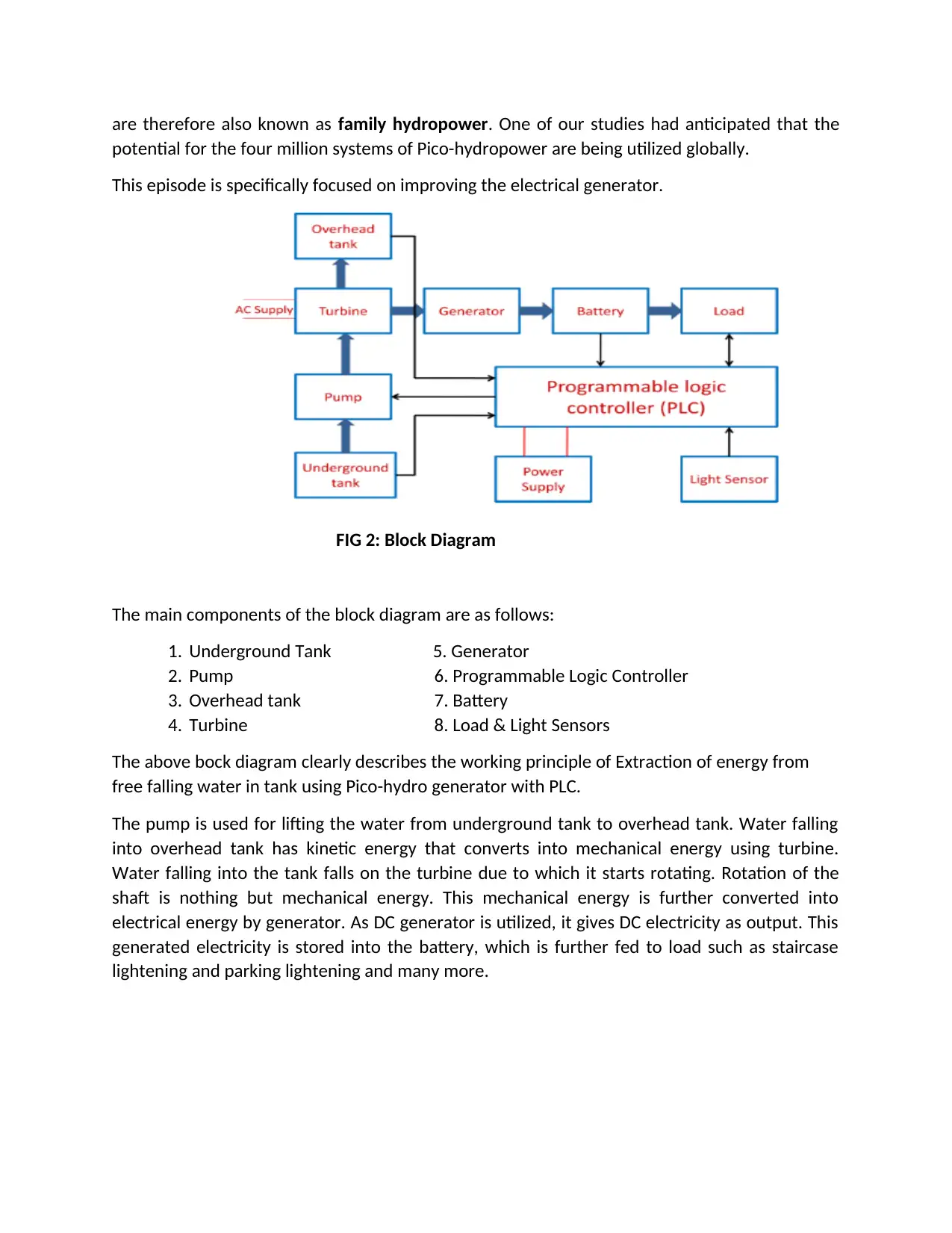
This project focuses on extracting energy from the kinetic energy of falling water in overhead tanks using a Pico-hydro generator controlled by a Programmable Logic Controller (PLC). The system aims to reduce human effort and water wastage while generating electricity. The project details the design and construction of a turbine, the implementation of PLC-based control for water level indication and lighting, and the challenges encountered during the project. The Pico-hydro generator converts the kinetic energy of the falling water into mechanical energy via a turbine, which then drives a generator to produce electricity, stored in a battery for later use in applications such as staircase and parking lighting. The report includes details on the components used, the calculations performed, and the overall success of the project in achieving its objectives of energy extraction and automation. Desklib provides access to this project and many other solved assignments for students.

CARRIER EPISODE 3
EXTRACTING ENERGY FROM FREE FALLING WATER IN THE TANK
USING PICO – HYDRO GENERATOR WITH PLC
EXTRACTING ENERGY FROM FREE FALLING WATER IN THE TANK
USING PICO – HYDRO GENERATOR WITH PLC
Paraphrase This Document
Need a fresh take? Get an instant paraphrase of this document with our AI Paraphraser

CE3.1 INTRODUCTION.
CE3.1.1 CHRONOLOGY
This project was done during my undergraduate studies at Sri Ramanathan Engineering College,
Tiruppur. The duration of this project was 2 months from 09thAugust, 2012 to 16thOctober,
2012. This episode contains the details of the project work named “Extracting Energy from Free
Falling Water in the Tank Using Pico – Hydro Generator With PLC”which was initiated by the
faculty out of my interest and skills in Electrical Engineering.
CE3.1.2 POSITION
Memberof the Project.
CE3.2 BACKGROUND.
CE3.2.1 NATURE OF THE PROJECT
The work dealt with extraction of energy from the falling water in the tank by utilizing
Pico-hydro generator with PLC along by reducing human efforts with high efficient working. The
increasing demand of energy has forced us to look at the other options different from
conventional means of exploiting energy, as conventional sources of energy are exhaustible. In
our society every home, apartment, office, hotel, hospital, etc. have water tank at the top most
floor. Each tank takes minimum one hour to completely fill with water. The water falling into
the tank is with kinetic energy which can be extracted to generate electricity. For this purpose,
the Pico-hydro turbine generator is used. It gives extraction of maximum energy from free
falling water.
This project is very effective and easily applicable to water tank because it gives
constant electrical output, as the water falling into the tank is twice daily (most cases).
CE3.2.2 OBJECTIVE OF THE PROJECT
The chief intend of the projectis,
To extract energy from falling water.
To save energy and reduce water wastage.
To design the project with PLC operator.
To reduce human efforts.
CE3.2.3 MY NATURE OF WORK.

I had caught up myself into the diverse work of calculation and evaluation of the
efficiencies of the project. As an electrical engineer, I had entire knowledge of power generator
and electrical power system. Have implemented several ideas in the system to reduce the
human efforts and being a part in designs and constructing the machine components. Also had
referred all the probable features of the process of design of the Pico hydro generator. I had
even involved myself into the development specifications of the site, testing as well as planning
of the components of electrical. I made sure that the project becomes successful at every
aspect.
CE3.2.4 ORGANIZATIONAL STRUCTURE OF PROJECT.
FIG: 1 - Organizational Structure of Project.
CE3.2.5 STATEMENT OF DUTIES.
a. Literature Review.
b. Implementing several features to reduce the human efforts.
c. To measure the machine efficiency.
d. Listing down the Inventories and Components used and testing them.
e. Design, Construction and assembling of components.
CE3.3 PERSONAL ENGINEERING ACTIVITY
CE 3.3.1 COMPREHENDING THE THEORY OF THE PROJECT
Being student engineer i did a lot of extensive research and analysis to understand the
complete mechanism of the project. At the extremely negligible sizes, these kinds of systems
are mostly appropriate for the particular households or the small bunches of households and
⊘ This is a preview!⊘
Do you want full access?
Subscribe today to unlock all pages.

Trusted by 1+ million students worldwide

are therefore also known as family hydropower. One of our studies had anticipated that the
potential for the four million systems of Pico-hydropower are being utilized globally.
This episode is specifically focused on improving the electrical generator.
FIG 2: Block Diagram
The main components of the block diagram are as follows:
1. Underground Tank 5. Generator
2. Pump 6. Programmable Logic Controller
3. Overhead tank 7. Battery
4. Turbine 8. Load & Light Sensors
The above bock diagram clearly describes the working principle of Extraction of energy from
free falling water in tank using Pico-hydro generator with PLC.
The pump is used for lifting the water from underground tank to overhead tank. Water falling
into overhead tank has kinetic energy that converts into mechanical energy using turbine.
Water falling into the tank falls on the turbine due to which it starts rotating. Rotation of the
shaft is nothing but mechanical energy. This mechanical energy is further converted into
electrical energy by generator. As DC generator is utilized, it gives DC electricity as output. This
generated electricity is stored into the battery, which is further fed to load such as staircase
lightening and parking lightening and many more.
Paraphrase This Document
Need a fresh take? Get an instant paraphrase of this document with our AI Paraphraser

CE 3.3.2 ENGINEERING KNOWLEDGE AND SKILLS APPLIED IN THE PROJECT
The basic concept of the project is same as the hydropower plant where fuel for generation is
running water but here the flowing water source is free falling to the water tank.
Here the overall system is controlled and switched using PLC which is simple and can be
modified easily as per requirement of user. During the working the responsibility of calculating
the determinedPower output from the generator was mine and has calculated with the below
equation. At first, I was nervous; however, progressively I was well accustomed with the system
and the objectives of the project.
Output power of pump = w*Q*H
Where, w = Gravitational force (kilo newton /meter cube) = 9.81
Q = Actual liquid discharge at pump outlet liter per sec.
H = Head in meters.
From this calculation the value of energy can be extracted from the free falling water.
Apart from the above, I have implemented certain features in PLC to reduce the human efforts.
I proposed to have a Water level indicator with a simple transistor logic as per Fig 3. The base
collector supply is provided through the water short linking the both terminals. As this base
collector voltage is applied, transistor conducts through the collector emitter which is used as a
switch in between the 24 VDC and PLC input terminal. So as water reaches to the terminal
transistor applies 24 VDC to the input terminal and input signal given to the PLC that the Water
tank is at high level or the low level as per particular level indicator.
FIG 3:- Water Level Indication Circuit

Secondly, aDay light sensor – LDR, for automatic turn ON and OFF of the Parking and Staircase
lightning. This LDR will simply work as a switch and is connected in series with the 24VDC and
the PLC input pin.
Finally an Alarm to indicate the water level in bottom tank in case there is no water in the
bottom tank and pump goes in fault running condition.
CE 3.3.3 ACCOMPLISHMENT AND TASK PERFORMED
The Pico generator generally refers to systems below 5kW in size which can be
shared between many households in a community. During the projectI made sure that the
project becomes successful and meets all requirements and started the project by performing
literature research into the project topic. The Project knowledge was very few but I carried out
the preparatory studies from the Internet and some references.
As it was specified before, I was part of assembling and construction of the components which
was the main part in the project.
Design and Construction of Turbine.
The turbine consist of mainly two parts,
1. Turbine Hub.
2. Turbine Spoons.
Turbine Hub: -The turbine hub is made from the lid of a five gallon bucket4” in diameter. I have
divided it into 16 layout lines from the center of the hub to receive 16 PVC spoons made from
eight 1/2” 45 degree couplings cut in half. First I have Located a bucket lid and Set the
compass for 2” and drawn a 4” circle from the registration point. This is the considered as
the outside diameter of the hub. I have cut out the hub with a utility knife. From the
registration point, I have divided the hub into 16 layout lines. This is accomplished by
dividing the hub into 4 then 8 then 16 layout lines. I have made as accurate, as it will
affect the balance of the turbine.
⊘ This is a preview!⊘
Do you want full access?
Subscribe today to unlock all pages.

Trusted by 1+ million students worldwide

FIG 4 : - Turbine Hub. FIG 5:- Turbine Spoons.
Next, I have set the compass for 9/16” from the center registration point and draw a circle with
a diameter of 1 1/8”. The intersection of this circle and the layout lines will be where the PVC
spoons end.
Turbine Spoons: - I have made the spoons from PVC. 16 spoons are required and are made
from eight 1/2” 45 degree PVC couplings cut in half. The eight 1/2” 45 degree couplings are
cut down with a table saw. The finished width of the spoons is a little less than 1/2”. These
spoons are then pop riveted to the hub made in the previous section.
After the spoons have been made, I have made a layout line on the inside of the spoons on one
side 1/8” in from the edge. Next, using the awl a registration mark at 1/4” in and 5/8” in from
the end of the spoon onthe layout line have been made. Holding the spoon on a flat surface
and using the top of the spoon as a guide for drilling, a pilot hole at each of these marks
with a 1/32” drill have been made.Finally drilled out the pilot holes with a 1/8” drill bit. The
spoons for the turbine are pop riveted from the back of the hub, through the hub and through
the spoons.
FIG 6:- Turbine. FIG 7:- Generator Coupled with Turbine (Pico Generator).
The generation process is consisting of Pico-generator, which was nothing but the coupled
turbine with generator. This generator gives output to the battery to store the electricity. Here I
haveconnected the load such as lightening load of staircase and parking. This Pico-hydro
Paraphrase This Document
Need a fresh take? Get an instant paraphrase of this document with our AI Paraphraser

generator was giving constant output as the flow rate of water falling into the tank was
constant. The process of water filling into overhead tank was required daily or in many cases
twice a day so that the energy extracting gives sufficient energy required for staircase and
parking lightening.
In addition to the above after the construction of the turbine the same was tested and power
output of 90 watts were obtained.
Several implementationswere also incorporated in the system for efficient working and to
reduce human efforts.
CE 3.3.4 PROJECT COORDINATION
This project was a collaborative work of my team member and me. I made sure that the
project was completed successfully. I mainly undertook the designing part. My team members
and I were sometimes confused about the entire project. However, as time passed by, we were
able to clear our doubts and clarification. My supervisor helped us to clear our doubts quickly
and efficiently.
CE3.3.5 TECHNICAL CHALLENGES ENCOUNTERED IN MY WORK & THEIR SOLUTION
1. Spoon Placing on the Turbine Hub was quite difficult as if the spoons were not placed
in the exact right place based upon the layout lines, there will be needed to make a
new hub. However with careful considerations all the spoons were attached one by one.
CE 3.4 PROJECT REVIEW
CE 3.4.1 PROJECT OVERVIEW
This project leads to water saving as well as energy saving with self-generating
unit. The project of extraction of energy from falling water in the tanks by using Pico hydro
generator with PLC became successful with the great strategies and approaches. During tank
filling as per flow rate there may be water wastage if there is manual process to
operate pump. Hence automated operation prevent from water overflow. The lightening
load (staircase and parking) is switched according to the day light. So it also gives efficient
operation of lightening. The selection of the generator was the most important part for this
project. A dc generator of the system is an electrical machine that switches the mechanical
energy into direct current electricity. This conversion of energy is typically based on the theory
of the production of electromagnetic field that is dynamically induced. The main advantage of
this project is that it can be easily applicable in any sector. The second advantage is the cost
effectiveness of the project.
1 out of 8
Related Documents

Your All-in-One AI-Powered Toolkit for Academic Success.
+13062052269
info@desklib.com
Available 24*7 on WhatsApp / Email
Unlock your academic potential
Copyright © 2020–2025 A2Z Services. All Rights Reserved. Developed and managed by ZUCOL.