ENCORE 4010 Research Project: Friction Welding in Production
VerifiedAdded on 2023/01/17
|32
|6570
|493
Project
AI Summary
This research project, submitted by Karan Saggu for ENCOR 4010, delves into the process of friction welding. It begins with a problem statement emphasizing the growing use of friction welding for joining dissimilar materials and its impact on joint strength and safety. The project includes an abstract summarizing the technique's automation, advantages, and limitations. The introduction provides a background on friction welding, its working principle, and feasibility studies. The document details the advantages and disadvantages of friction welding and explores its industrial applications, including marine, aerospace, and railway industries. Different types of friction welding, such as inertial friction welding and continuous induction methods, are discussed. The project also includes a timeline, proposal metrics, and a conclusion, along with references. The research aims to provide a comprehensive overview of friction welding, its parameters, and its importance in various manufacturing sectors.
Master of Engineering technology
Student ID 30340364 Student Name Karan Saggu
Assignment Title Friction Welding in Production
Feedback / Assessment:
LECTURER’S SIGNATURE: DATE:
RESEARCH PROPOSAL
Course Code ENCOR 4010 Course Name Research Project 1
Date Submitted Lecturer’s Name Dr Ibrahim A Sultan
Tutor’s Name
Student ID 30340364 Student Name Karan Saggu
Assignment Title Friction Welding in Production
Feedback / Assessment:
LECTURER’S SIGNATURE: DATE:
RESEARCH PROPOSAL
Course Code ENCOR 4010 Course Name Research Project 1
Date Submitted Lecturer’s Name Dr Ibrahim A Sultan
Tutor’s Name
Paraphrase This Document
Need a fresh take? Get an instant paraphrase of this document with our AI Paraphraser
FRICTION WELDING 2
1 Table of Contents
2. Background...................................................................................................................................4
3. working Principle..........................................................................................................................4
5. Advantages and disadvantages of friction welding......................................................................5
5.1. Advantages of friction welding..................................................................................................5
5.2. Disadvantages of friction welding..............................................................................................6
6. Industrial applications of friction welding....................................................................................7
6.1. Marine and shipbuilding industries..........................................................................................7
6.2. Aerospace industry...................................................................................................................8
6.3. Railway industry........................................................................................................................8
6.4. Other industries include............................................................................................................8
7. Types of friction welding..............................................................................................................9
7.1. Inertial friction welding..............................................................................................................9
7.2. Continuous induction method................................................................................................10
7.3. Linear friction welding.............................................................................................................10
7.3.1. Process parameters.............................................................................................................13
7.3.2. Numerical simulation of inertia friction welding process of gh4169 alloy.........................14
7.4. Friction surfacing.....................................................................................................................18
9. Timeline.......................................................................................................................................22
10. Proposal metrics......................................................................................................................23
10.1. Scientific and Technical Merit..............................................................................................23
11. Conclusion...............................................................................................................................28
12. References...............................................................................................................................29
Table of Figures
Figure 1 ………………………………………………………………………………………………………………………………………………………………………11
Figure 2 ………………………………………………………………………………………………………………………………………………………………………12
Figure 3 ………………………………………………………………………………………………………………………………………………………………………13
Figure 4 ……………………………………………………………………………………………………………………………………………………………………….14
Table 1 …………………………………………………………………………………………………………………………………………22
Table 2…………………………………………………………………………………………………………………………………………23
Table 3 …………………………………………………………………………………………………………………………………………26
Table 4 …………………………………………………………………………………………………………………………………………27
FRICTION WELDING 3
Problem statement
The process of friction welding is augmenting rapidly in the amalgamation of dissimilar
materials within a less time and joints free of defection (Sahin, 2009). For instance,
nowadays, joining of dissimilar materials such as ferritic stainless steel and copper id
commonly applied for numerous industrial processes such as nuclear, automotive, electrical,
and chemical industries. While in a solid state, materials are continuously rubbed together
using friction welding and in the process, a lot of heat is generated between their interfaces.
When enough energy is produced, the rotation ceases and a comprehensive or an upset force
is provided in order to amalgamate the joint and produce a bond in solid state (Reddy & Rao,
2009). Some friction welding parameters such as the speed of rotation, comprehensive
pressure, friction pressure, and burn-off length apparently affect the strength of the resultant
joint. Thus, it is prudent to investigate on this impact to ascertain duration of the material
formed as well the safety of the users.
⊘ This is a preview!⊘
Do you want full access?
Subscribe today to unlock all pages.
Trusted by 1+ million students worldwide
FRICTION WELDING 4
Abstract
Friction welding is a solid state welding technique with high automation and good quality.it
has been broadly applied in various industries especially in aerospace and automobile
industries. Because of high level of automation and less process parameters, the inertial
friction is common in many fields. There are many merits which are associated with the use
of friction welding in production such as, it is fast method of welding as compared to other
welding techniques. Even though there are many benefits which are associated with it, there
are also some drawbacks such as, is mainly used in round bars which have the same cross
section.
Paraphrase This Document
Need a fresh take? Get an instant paraphrase of this document with our AI Paraphraser
FRICTION WELDING 5
1. Introduction
Friction welding is defined as Solid state or a simply forge whereby the welding process
occurs between two mating surfaces of metals through the application of friction between
them. The welding technique has been adopted by well-known international companies in in
America and Europe such as American Manufacturing Foundry and Rockwell international to
manufacture their machines.
Friction welding is considered to be very essential in the production industry, by adopting
this welding method the high overhead costs which the companies will undergo to have this
technique in place will be balanced with the high production rates and lower labour
requirements.
The friction welding technique has many dimensional and hardware which are easily
adjustable making it to be very significant in the production of very small parts and
components. There are many industrial applications where friction welding can be applied
such as the machine and spare part production.
2. Background.
The process of friction welding was first discovered in the late 1920s, however during
that time there was very little data which was recorded about its use. A detailed discussion
about friction welding was recorded in the USSR in the early 1960s, but that time it was
described as ‘very doubtful, as a production technique due to the challenges in generating
reciprocating linear motion. The fist well-structured industrial research into friction welding
took place in the 1980s at TWI, UK, while the first ever research academic to be to be
recorded took place at Ohio State University, and the University of Bristol, UK.
FRICTION WELDING 6
3. Working Principle
The friction welding technique works on the basic principle of friction. In the process of
welding, friction is used to create heat at the interfaces surfaces (Anderson, 2016). The heat is
used to join the two work pieces through the application of the external pressure at the work
pieces surfaces. In friction welding, the friction is applied until the plastic forming
temperature is reached which is usually900-1300oc for steel. After the heating process,
pressure which is uniformly increasing is applied to both of the metal work pieces until they
make a permanent joint.
4. Feasibility Study
This study evaluates the feasibility of friction welding for production at the
Federation University of Australia. As the project is new, it consumes much
resource, therefore it is prudent to do feasibility check. This illustrates that the
research is workable as well giving benefits to this research. The research will
be conducted in the Laboratory and Friction Welding Australia which is a
specialist in this type of technology since 2012. Thus, the research is technically
feasible.
A compressive study has been done for financial feasibility to ascertain it.
(Overfield, 2010) The total cost was analysed. The financial merits outweighed
the financial demerits. The benefits were analysed to gage the study whether is
viable and significant in terms of financial aspects. It was proved that, financial
feasibility of the research is important within the reach.
⊘ This is a preview!⊘
Do you want full access?
Subscribe today to unlock all pages.
Trusted by 1+ million students worldwide
FRICTION WELDING 7
5. Advantages and disadvantages of friction welding
5.1. Advantages of friction welding
There are many merits which are associated with the use of friction we in production.
(Mahadzir, 2016)Some of the merits include:
It’s easier and convenient to join metals which are not similar and some of which are
considered to be unweldable or incompatible.
Friction welding is very fast method of welding as compared to other welding
techniques (Granjon, 2014).
Due to their versatility the friction welders are able to join a wide range of materials,
shapes and sizes without any challenge.
In this friction welding joint preparation is not of great importance since, saw cut,
machine and even the sheared surfaces are weldable.
The resulting joints are of forged quality, with up to 100% butt joint weld through the
contact area.
Human errors are eliminated by machine controlled process, and the quality of the
weld is independent of the operator skill.
It is environmental friendly as there is no objectionable fumes, gases or smoke that
are generated which needs to be exhausted.
In friction welding there are no consumable that are required, no filler material, flux
or shielding gases.
The power requirements for friction welding as low as 20% of that which is required
for conventional welding processes.
Since there is no melting which occurs there is no solidification defects such as gas
porosity, slag or segregation inclusions.
Paraphrase This Document
Need a fresh take? Get an instant paraphrase of this document with our AI Paraphraser
FRICTION WELDING 8
5.2. Disadvantages of friction welding
Even though there are many benefits which are associated with friction welding it has
also some drawbacks such as: (Benini, 2011)
This technique of welding is mainly used in round bars which have the same cross
section. Due to that the bars which are not of the same cross section cannot be welded. In
some industries welding of metals which are not round in shape is very common the
application pf friction welding for such cases is limited (Sahin, 2016).
There are exist holes left when the tools are withdrawn. Most of the metal bars which are
to be joined together are held by strong tools which drills holes through them.
Friction welding requires extensive clamping
Needs special backing support
The cost of setting up a friction welding facility are very high. The equipment and
machines which are used for friction welding are very expensive to acquire. This makes a
lot of people to move to the convention welding which is much easier and cheaper.
The design of the joints is very limited.
It involves critical preparations of work pieces (Welding InstituteElsevier Science &
Technology, 2010).
6. Industrial applications of friction welding
Many production industries all over the world are experiencing the high costs of energy
due to the amount of energy which is consumed during the production process’s adoption of
friction welding can greatly assist in solving this challenges (Yilbas, 2016). The friction
welding has been applied in various industrial applications as discussed below:
FRICTION WELDING 9
6.1. Marine and shipbuilding industries
The marine and shipbuilding are among the earliest industries to adopt friction welding
for commercial applications (Anderson, 2016). Friction welding is suitable for the following
applications:
Panels for side, decks, floors and bulkhead.
Superstructures and Hulls
Aluminium extrusions
Booms and Mast for example for sailing boat
6.2. Aerospace industry
Currently the aerospace industry is welding production parts and prototype by application
of friction welding. There exist opportunities to weld, ribs, spars and stringers for civilian and
military aircrafts (Vill', 2015). The friction welding process can be considered for the
following:
Fuselage, empennages, wings
In the case of space vehicle the friction welding can be considered for cryogenic fuel
tank
Scientific and military rockets
Aviation fuel tanks
6.3. Railway industry
The commercial production of high speed trains which are made from aluminium
extrusions that can be joined through friction welding has been published and the applications
include:
Trams, underground undercarriages and the rolling stock of railways
Good wagons and railway tankers
⊘ This is a preview!⊘
Do you want full access?
Subscribe today to unlock all pages.
Trusted by 1+ million students worldwide
FRICTION WELDING 10
Container bodies (American Welding Society. Committee on Friction Welding, 2012)
6.4. Other industries include
Electric motor housing
Kitchens and cooking equipment
Gas cylinders and gas tanks
Axle tube, gears, drive line, valves and other components are friction welded.
Connecting rods, Gear levers, drill bits are friction welded
It regularly used to replace casting or forging assembly
Truck rollers, and hydraulic piston rods are friction welded
In welding shafts and tubes
In electrical industries it is used for welding aluminium and copper equipment
In pumps friction welding is used to weld pump shafts (Singh, 2016).
7. Types of friction welding
There is existence of many variations in the process which work on the same principle, due to
that there are various types of friction welding as listed below:
1. Continuous induce friction welding
2. Linear friction welding
3. Spin welding/Inertial friction welding
4. Friction surfacing
7.1. Inertial friction welding
Inertial Friction Welding refers to a variation of the friction welding in which the required
energy to make the weld is provided mainly by the stored rotational kinetic energy of the
welding machine (Blau, 2012). In the Inertial Friction welding, one of the two workpieces
is connected to a flywheel while the other is prevented from rotating. The flywheel is then
Paraphrase This Document
Need a fresh take? Get an instant paraphrase of this document with our AI Paraphraser
FRICTION WELDING 11
accelerated to a given rotational speed which is predetermined, storing the required
energy. The motor driver is disengages and then the work pieces are joined together by
the friction welding force. This makes the faying surfaces to rub to each other under
pressure. The kinetic energy which is stored in the rotating wheel is released as heat
through friction at the interface of the weld as the wheel speed decreases. A forge force
might be applied before the flywheel completely stops (Wang, 2013). After rotation has
stopped the forge force is maintained for a predetermined period.
7.2. Continuous induction method.
In this welding process, the rotor I connected together with band brake. When the plastic
temperatures are achieved, the band brake which was connected comes into action with the
main role being is to stop the rotor but at the same time the pressure which is applied
continue to increase until the two work pieces joints well and thus the weld is achieved
(Yilbas, 2016).
7.3. Linear friction welding
Linear Friction welding is a solid-sate joining process which works through oscillating
one workpiece relative to another while under a large compressive force as shown in fig 1
below. The friction which can exist between the oscillating surfaces generates heat that
causes the material of the interface to plasticise (Blaga, 2015). The material which is
plasticised is then expelled from the interface causing the workpiece to burn-off (shorten) in
the compressive force direction. In the process of burn-off the interface contaminants such as
foreign oxides and particles that can affect the properties and possibly the service life of a
weld are expelled. Once the workpieces are free from contaminants the metal to metal contact
occurs which leads to formation of an integral bond (Vill', 2015). Linear friction welding
unlike other methods of friction welding it takes place in four phases as listed below:
FRICTION WELDING 12
I. Phase 1: Initial stage
II. Phase 2: transition stage
III. Phase 3: Transition stage
IV. Phase 4: Forging and Deceleration phase
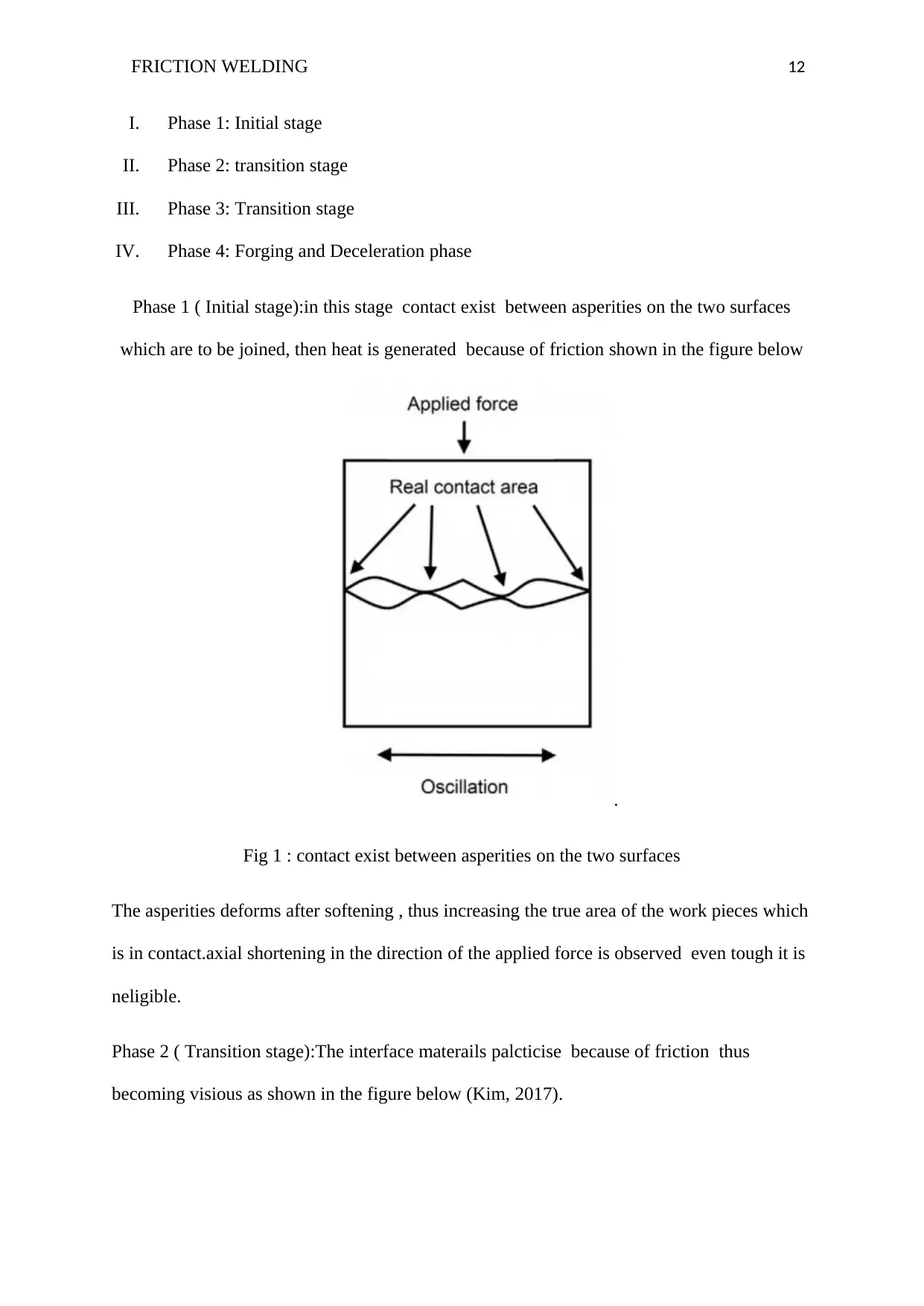
Phase 1 ( Initial stage):in this stage contact exist between asperities on the two surfaces
which are to be joined, then heat is generated because of friction shown in the figure below
.
Fig 1 : contact exist between asperities on the two surfaces
The asperities deforms after softening , thus increasing the true area of the work pieces which
is in contact.axial shortening in the direction of the applied force is observed even tough it is
neligible.
Phase 2 ( Transition stage):The interface materails palcticise because of friction thus
becoming visious as shown in the figure below (Kim, 2017).
I. Phase 1: Initial stage
II. Phase 2: transition stage
III. Phase 3: Transition stage
IV. Phase 4: Forging and Deceleration phase
Phase 1 ( Initial stage):in this stage contact exist between asperities on the two surfaces
which are to be joined, then heat is generated because of friction shown in the figure below
.
Fig 1 : contact exist between asperities on the two surfaces
The asperities deforms after softening , thus increasing the true area of the work pieces which
is in contact.axial shortening in the direction of the applied force is observed even tough it is
neligible.
Phase 2 ( Transition stage):The interface materails palcticise because of friction thus
becoming visious as shown in the figure below (Kim, 2017).
⊘ This is a preview!⊘
Do you want full access?
Subscribe today to unlock all pages.
Trusted by 1+ million students worldwide
1 out of 32

Your All-in-One AI-Powered Toolkit for Academic Success.
+13062052269
info@desklib.com
Available 24*7 on WhatsApp / Email
![[object Object]](/_next/static/media/star-bottom.7253800d.svg)
Unlock your academic potential
Copyright © 2020–2026 A2Z Services. All Rights Reserved. Developed and managed by ZUCOL.