Research Project: Thermal Analysis of Friction Welding with Abaqus CAE
VerifiedAdded on 2022/11/14
|58
|12052
|352
Project
AI Summary
This project report focuses on the thermal analysis of friction welding, a solid-state welding technique widely used in industries such as aerospace and automotive. The study employs Abaqus CAE software to simulate the heat generation and distribution during the friction welding process. The introduction provides an overview of friction welding, its types (including inertial, continuous induction, and linear friction welding), key parameters, advantages, disadvantages, and industrial applications. The literature review covers previous research on friction welding, particularly focusing on thermal analysis and the use of finite element analysis. The methodology involves creating a geometry, defining simulation characteristics, meshing, and applying boundary conditions within Abaqus CAE. The results section presents the findings of the simulation, including temperature distributions and deformed shapes. The discussion explores the heat effects, discrepancies, and errors in the thermal analysis. The conclusion summarizes the key findings, and recommendations for future work are provided. The project highlights the importance of thermal analysis in optimizing friction welding processes.

RESEARCH METHODOLOGY
[Author Name(s), First M. Last, Omit Titles and Degrees]
[Institutional Affiliation(s)]
1
[Author Name(s), First M. Last, Omit Titles and Degrees]
[Institutional Affiliation(s)]
1
Paraphrase This Document
Need a fresh take? Get an instant paraphrase of this document with our AI Paraphraser
ABSTRACT
Friction Welding refers to a welding technique of solid state that is characterized by very high
automation as well as quality. In the method of friction welding, there is production of thermal
energy. The process involves rubbing of very strong surfaces so that there is production of heat.
Considering that this particular method is transient as well as excluding an axis-symmetrical
condition of heating, it is important to the heat assessment to be formulated. The technique of the
friction welding works on the basic principles of welding just like any other normal types of the
welding in the field of metallurgy and metal treatments. In the welding process using this
particular technique, there is use of the friction to create heat at the interfaces of the work pieces
which are majorly metals. This heat is used in joining the two work pieces through application
pressure which is sourced externally. The application of friction is done until that point when the
temperature of the plastic formation is achieved. This particular thesis addresses the concept of
thermal analysis of the friction welding while using the Abaqus CAE software
2
ACKNOWLEDGEMENT
I wish to thank the Almighty father who has been so merciful and caring for the entire period that
I have been working on this particular project. My sincere appreciation goes to
Prof……………….for his endless guidance. To my friends and relatives who have contributed
either financially or in kind towards this project, I am very grateful.
STATEMENT OF ORIGINALITY
I hereby certify that other than where specific acknowledgement has been made, the present
work belongs to the author himself and has not been previously submitted in part or as a whole to
allow for any academic qualifications.
3
⊘ This is a preview!⊘
Do you want full access?
Subscribe today to unlock all pages.
Trusted by 1+ million students worldwide
Contents
ABSTRACT....................................................................................................................................................2
ACKNOWLEDGEMENT.................................................................................................................................3
STATEMENT OF ORIGINALITY......................................................................................................................3
List of figures...........................................................................................................................................3
List of Tables............................................................................................................................................4
CHAPTER 1: INTRODUCTION........................................................................................................................5
Overview.............................................................................................................................................5
LITERATURE REVIEW....................................................................................................................................8
Types of friction welding.......................................................................................................................13
Inertial friction welding.....................................................................................................................13
Continuous Induction Method...........................................................................................................14
Linear Friction Welding....................................................................................................................14
Friction Stir Spot Welding (FSSW)...................................................................................................17
Key Parameters in Friction Welding.......................................................................................................18
Advantages and Disadvantages of the friction welding.........................................................................22
Benefits of friction welding................................................................................................................22
Limitations of Friction Welding............................................................................................................22
Applications of friction welding within the industry.............................................................................24
Ship building and marine industries...................................................................................................24
Aerospace Industry............................................................................................................................24
The inverse analysis as a method of heat transfer..............................................................................25
7.1 Simulation procedure.......................................................................................................................29
Step 1. Geometry drawing.................................................................................................................29
Rod 2 geometry.................................................................................................................................30
Step 2 assembly.................................................................................................................................31
Step 3. Defining the simulation characteristics..................................................................................32
Step 4: meshing.................................................................................................................................33
Boundary conditions..........................................................................................................................34
4
Paraphrase This Document
Need a fresh take? Get an instant paraphrase of this document with our AI Paraphraser
CHAPTER 3: RESULTS.................................................................................................................................34
CHAPTER 4: DISCUSSION...........................................................................................................................39
Heat effect in FSSW...........................................................................................................................41
Friction Welding Thermal analyses discrepancies and errors................................................................46
CHAPATER 5: CONCUSION.........................................................................................................................46
CHAPTER 6: RECOMMEDATIONS FOR FUTURE WORK...............................................................................49
REFERENCES..............................................................................................................................................50
APPENDIX..................................................................................................................................................56
List of figures
Figure 1: …………………The existing contact between the two asperities on the surfaces
Figure: ……………………..2 Transition phase
Figure 3:………………….. ……The tool shoulder
Figure 4: …………………………Graphical Interpolation
Figure 5: …………………………….. Thermocouples location within the friction stir welding in
consideration to the case of 300rpm tool rotational speed
Figure 6: ……………………………………….. rod 2 geometry characteristics
Figure 7: material settings, steel was used, with the characteristics shown on screenshot.
Figure 8 : ………………………………………..rod 2 geometry characteristics
5
Figure 9: ……………………………………………….part 1 meshing
Figure 10: …………………………………………………..job submitted successfully for
analysis as shown
Figure 11: …………………………………………………deformed shaped
Figure 12: ………………………………………………..undeformed shaped
Figure 13 : …………………………………………………..temperature vs time plots
Figure 14 : ………………………………………Undeformed shaped
Figure 15: ……………………………………..Temperature and time graphical analysis
Figure 16: ……………………………………Contact penetration
List of Tables
Table 1: ………………………………………………..Data for impact energy in welded samples
Table 2: ……………………………………………………..Temperature dependent
Characteristics of the steel
6
⊘ This is a preview!⊘
Do you want full access?
Subscribe today to unlock all pages.
Trusted by 1+ million students worldwide
CHAPTER 1: INTRODUCTION
Overview
Friction Welding refers to a welding technique of solid state that is characterized by very high
automation as well as quality. In the method of friction welding, there is production of thermal
energy. The process involves rubbing of very strong surfaces so that there is production of heat.
Considering that this particular method is transient as well as excluding an axis-symmetrical
condition of heating, it is important to the heat assessment to be formulated (Becker, Beeson &
Marcusen 2017). The implementation of the thermal assessment is done based on the Fourier
equation of the conduction. The solution of the conduction is obtained through applications of
various aspects of the boundary conditions. Friction welding as a technique utilizes the concepts
of the green engineering. This is because the plastic performance and friction at the interfaces of
all the work pieces determines the strength of the of the weld joints (Chiumenti et al 2013).
In this regard, it will use inconsumable device in the creation of the coalescence between the
work pieces. This particular method can be used in the production of the equipment by the use of
traditional systems of the machines for welding between materials which are different and those
which are similar as well as their alloys. It can also be applied in the case of the welding between
strengthened composites of metals. Using joints of the friction welds implies that cost saving and
weight will be reduced significantly. When this kind of welding is compared with the standard
methods of the welding which is commonly refered to as the "freeze welding method", the
former is found to be effective and easier in terms of the implementations. Its implementation
ranges from crack correction to joining of the members like covers and stuffs to other parts of the
job (Kalemba, Hamilton & Dymek 2014). This particular technique again allows for the repair of
7
Paraphrase This Document
Need a fresh take? Get an instant paraphrase of this document with our AI Paraphraser
the components. The mechanism of adding harder materials to probe the softer material element
is commonly refered to as method of the friction welding
Thermoplastics substances are regarded to be structural materials that are used in place of metals
in various activities conducted in industries such as automotive, building, aerospace depending
on the number of advantages such as weight saving, minimized cost of manufacturing high
thermal insulation and flexibility. Apart from design flexibility, the constituents of complex
components include various conjoined subparts. Due to this, processes that involve welding
activities are installed; though to eradicate the related principle limitations of the processes, the
applied practices are either to minimize the time of processing and enhancing the joint quality
(Darvazi & Iranmanesh 2014).
Friction welding is a solid state welding technique with high automation and good quality.it has
been broadly applied in various industries especially in aerospace and automobile industries.
Because of high level of automation and less process parameters, the inertial friction is common
in many fields. There are many merits which are associated with the use of friction welding in
production such as, it is fast method of welding as compared to other welding techniques. Even
though there are many benefits which are associated with it, there are also some drawbacks such
as, is mainly used in round bars which have the same cross section
One of the most popular welding techniques is Friction Spot Stir Welding (FSSW), this is
because, the resulting joints are of high mechanical performances regarded in terms of rigidity of
the stirred region of close proximity to base substances, minimized Heat Affected Zone and
minimized temperature (related to the one of the material fusion). Further, the process is
characterized by low consumptions of energy, simple machines required no external sources of
8
heating or cover gas required. This has facilitated the spread of these processes and at the same
time has installed a lot of interest to the scholars to uncover various technological areas of
application (Dialami et al.2015).
Transverse speed dearth is what brings the difference between FSSW and FSW, the joints
produced by FSSW are therefore regarded as spot joints but not continuous joint welds. The
production of heat as a result of friction in FSSW is due to the rubbing that occurs between the
tool pin and the material with vertical extrusion. The exerted upsetting action by the shoulder of
the tool on the stirred material results into the formation of weld nut. Due to the challenges
experienced with the ancient application of welding techniques on joining materials like alloys of
aluminum, the use of FSSW and FSW has gone beyond control covering a wide range of metals
like copper, titanium, magnesium or steels of high strength and also composites as well as
thermoplastics.
Further, considering the semisolid nature, the processes of FSSW and FSW are not greatly
affected by physical or chemical properties of the materials to be joined; therefore, they give
chance of even joining materials that are not similar. One of the most common polymers is
polypropylene since it is readily available and the associated cost is competitive. Polypropylene
is a thermoplastic material with well-known mechanical properties. The necessity of generating
great and complex parts form polymers like polypropylene has resulted into high demands for
joining. In addition to that, following the increased enhancements on engineering plastics, more
reliable, high, rapid productivity as well as effective techniques of joining are on great demand.
9
⊘ This is a preview!⊘
Do you want full access?
Subscribe today to unlock all pages.
Trusted by 1+ million students worldwide
LITERATURE REVIEW
The process of the friction welding was discovered first in the late 1920s although there was very
little information which had been recorded about the use of the same technique. A
comprehensive as well as detailed discussion about the friction was recorded in the early 1960s
in USSR. The time however was never convincing as for the case today. The first well-structured
research on the industrial activities involving the same technique took place in the 1980s in UK.
While the first academic research was in the Ohio State University as well as University of
Bristol.
FSW that is the friction welding sir is a new state-of-the art state of solid joining process. This
technique of joining metals is derived from welding convectional friction. Typically, FSW is a
cylindrical S rotating pin tool which is forced to plunge in the welded plates like workpiece
which moved along their line of contact. In the operation process, heat is generated by contact
friction in between the tool and the workpiece that soften the material. The material which is
plasticized is stirred using the tool and then forced to flow along the sides as well as the tool
back and tool advance (Stöger, Wittmann & Leko 2014).
When the temperature decreases, the solid substance which is continuous in the joint is formed
between the two plates to be welded. Since the higher the temperature, the lower FSW process
less than the workpiece material melting temperature, FSW yield fine microstructure, cracking
absence, a lower residual distortion as well as the loss of the alloying element which are the
major advantages of this process phase (Shi, Wu, & Liu 2015). However, in the traditional fusion
weld, a softened zone which is affected by the heat as well as the tensile residual stress parallel
to the existing weld.
10
Paraphrase This Document
Need a fresh take? Get an instant paraphrase of this document with our AI Paraphraser
However, FSW is a considered to be a new technology in welding, but it has been studied
extensively either in the academic or in industrial communities for various alloys of aluminum
which include alloys that cannot be weld easily like AA2195 having lithium as well as AA7075.
Currently most researchers always focus on the transfer of heat and the FSW temperature
analysis. One of the researchers did a presentation of the measured workpiece temperature
distribution in the FSW. However, some of these researchers proposed a simple model of hear
transfer in order to predict the distribution of the temperature within the FSW workpiece. While
some developed a model of a moving heat source within the finite element analysis as well as the
transient temperature, stress residual as well as the FSW distortion process (Zboray et al 2014).
However, some of the researchers have developed models of three dimensional heat flow to
assist in predicting FSW temperature field. Three of these researchers did an investigation on the
effect of the tool shoulder material as well as tool on the heat input during the FSW. The current
report is the measured residual stresses in the friction stir welds of 202T3 as well as 6013-T6
aluminums. Some of them used a simplified two dimensional axisymmetric medal. The
investigation heat energy variation as well as that of the temperature as per the FSW production
in pin tool and even in the workpiece.
Most of these investigations illustrate that aluminum alloys FSW process yield weld with a lower
distortion, low cost and high quality. A better stromal performance is considered to be the
primary advantage of the application of this technology. The best example is the demonstration
of the tremendous potential as well as the successful aluminum FSW application within airframe
structure. FSW principle can be used in joining some alloy materials including steels as well as
titanium. Therefore, it has been already considered as the current tool materials that are being
11
used within the FSW since the aluminum are insufficient for production application in various
hard alloy materials (Meyghani et al 2017).
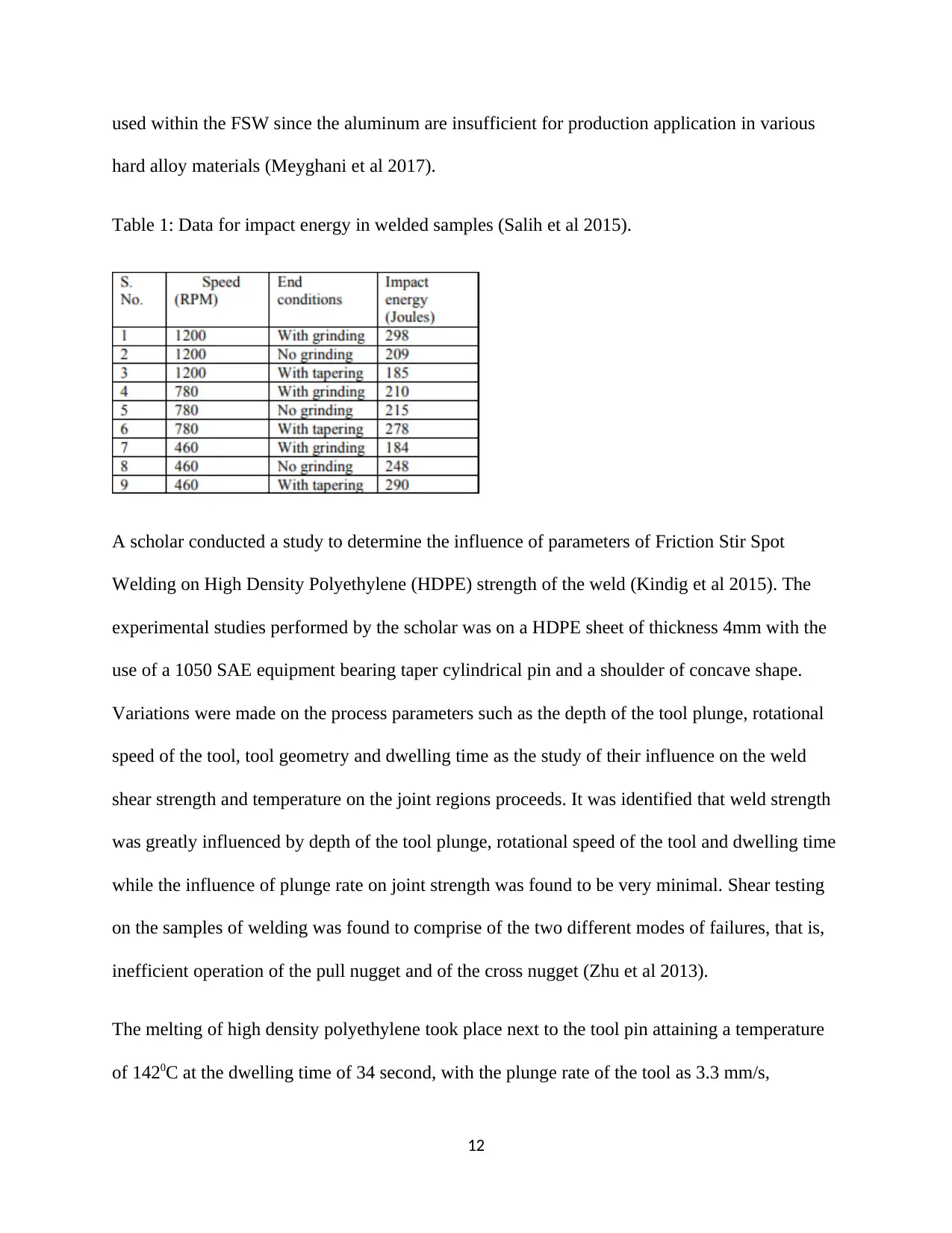
Table 1: Data for impact energy in welded samples (Salih et al 2015).
A scholar conducted a study to determine the influence of parameters of Friction Stir Spot
Welding on High Density Polyethylene (HDPE) strength of the weld (Kindig et al 2015). The
experimental studies performed by the scholar was on a HDPE sheet of thickness 4mm with the
use of a 1050 SAE equipment bearing taper cylindrical pin and a shoulder of concave shape.
Variations were made on the process parameters such as the depth of the tool plunge, rotational
speed of the tool, tool geometry and dwelling time as the study of their influence on the weld
shear strength and temperature on the joint regions proceeds. It was identified that weld strength
was greatly influenced by depth of the tool plunge, rotational speed of the tool and dwelling time
while the influence of plunge rate on joint strength was found to be very minimal. Shear testing
on the samples of welding was found to comprise of the two different modes of failures, that is,
inefficient operation of the pull nugget and of the cross nugget (Zhu et al 2013).
The melting of high density polyethylene took place next to the tool pin attaining a temperature
of 1420C at the dwelling time of 34 second, with the plunge rate of the tool as 3.3 mm/s,
12
hard alloy materials (Meyghani et al 2017).
Table 1: Data for impact energy in welded samples (Salih et al 2015).
A scholar conducted a study to determine the influence of parameters of Friction Stir Spot
Welding on High Density Polyethylene (HDPE) strength of the weld (Kindig et al 2015). The
experimental studies performed by the scholar was on a HDPE sheet of thickness 4mm with the
use of a 1050 SAE equipment bearing taper cylindrical pin and a shoulder of concave shape.
Variations were made on the process parameters such as the depth of the tool plunge, rotational
speed of the tool, tool geometry and dwelling time as the study of their influence on the weld
shear strength and temperature on the joint regions proceeds. It was identified that weld strength
was greatly influenced by depth of the tool plunge, rotational speed of the tool and dwelling time
while the influence of plunge rate on joint strength was found to be very minimal. Shear testing
on the samples of welding was found to comprise of the two different modes of failures, that is,
inefficient operation of the pull nugget and of the cross nugget (Zhu et al 2013).
The melting of high density polyethylene took place next to the tool pin attaining a temperature
of 1420C at the dwelling time of 34 second, with the plunge rate of the tool as 3.3 mm/s,
12
⊘ This is a preview!⊘
Do you want full access?
Subscribe today to unlock all pages.
Trusted by 1+ million students worldwide
1 out of 58
Related Documents


Your All-in-One AI-Powered Toolkit for Academic Success.
+13062052269
info@desklib.com
Available 24*7 on WhatsApp / Email
![[object Object]](/_next/static/media/star-bottom.7253800d.svg)
Unlock your academic potential
Copyright © 2020–2026 A2Z Services. All Rights Reserved. Developed and managed by ZUCOL.