Analysis and Allocation of Functions in Systems Engineering Report
VerifiedAdded on 2023/03/20
|15
|2983
|44
Report
AI Summary
This report provides a comprehensive overview of functional analysis and allocation within systems engineering. It begins by defining functions and allocation, emphasizing the iterative, top-down approach used in system engineering, involving functional analysis, synthesis, and allocation. The report details functional analysis, which involves analyzing system input requirements to identify functions and subfunctions, and functional allocation, which assigns requirements to meet performance and design needs. It explores the Functional Flow Block Diagram (FFBD) for describing system requirements and discusses various approaches to functional analysis, including functional partitioning and the use of functional trees and output matrices. The report also covers functional allocation methods, emphasizing the importance of traceability and the use of function level decomposition for automation proposals. The conclusion highlights the co-evolution of practice and technology in functional allocation, emphasizing the importance of these methods for effective system design and implementation.

Running Head: Functional Analysis & Allocation 1
Topic
Name
Institutional Affiliation
Topic
Name
Institutional Affiliation
Paraphrase This Document
Need a fresh take? Get an instant paraphrase of this document with our AI Paraphraser
Introduction
The functionality of any system requires the occurrence of different actions that are
aimed at a achieving a particular objective. The actions are normally referred to as activities,
responses, functions, or operations. A much standard description of a function is input
transformation into outputs through a process that may involve the creation, destruction, or
modification of elements. Also, the process of developing output may involve a null
transformation. The structural view of any system should be able to correlate with its behavioral
aspects. Allocation can be described as the design association in which a collection of behavioral
aspects is mapped onto another collection of structural elements. The requirements fulfillment
and functional completeness of a system is considered to be possible through allocation.
System engineering is dependent on the repetitive, top-down, hierarchical breakdown of
requirements outlined in a system. The approach, as it relates to systems engineering involves the
implementation of concurrent activities that are based on Functional Allocation, Synthesis, and
Analysis (Sage, & Rouse, 2009). The repetitive process is normally signaled by system level
breakdown, and this goes to Functional subsystem stage and Assembly program level, which is
also known as software/hardware Configuration (Pai, 2012). As each level goes on developing,
the activities associated with synthesis, functional analysis, and allocation are consequently
completed before moving to the proceeding stages.
Functional analysis involves the use of a systems input requirements that were
established at the mission and operational analysis to continuously analyze and identify functions
and subfunctions associated with a system. This helps to note the different approaches that can
be used to attain requirements of a system (Vasconcelos, et al., 2015). Functional analysis
usually needs to be undertaken in conjunction with synthesis and allocation functions. System
engineering will normally take into account all types of support operations, and then it outlines
the most suitable requirements for performance for all the primary functions and sub-functions
that have been outlined. Time analysis will also be undertaken by Functional analysis when and
where time is essential for the functional performance (Seyyedi, Ajam, & Farahat,2010).
System engineering Functional Allocation, on the other hand, assigns the necessary
requirements for ensuring that performance and design needs can be met. This is done for all the
primary functions and subfunctions in a system. Derived system requirements will be sufficiently
outlined in order to allow efficient allocation of resources to processing data, hardware, software,
and personnel. Functional allocation will always occur in conjunction with Synthesis and
Functional analysis. Functional allocation requires that Traceability of a system is always
maintained (Eisner, 2008).
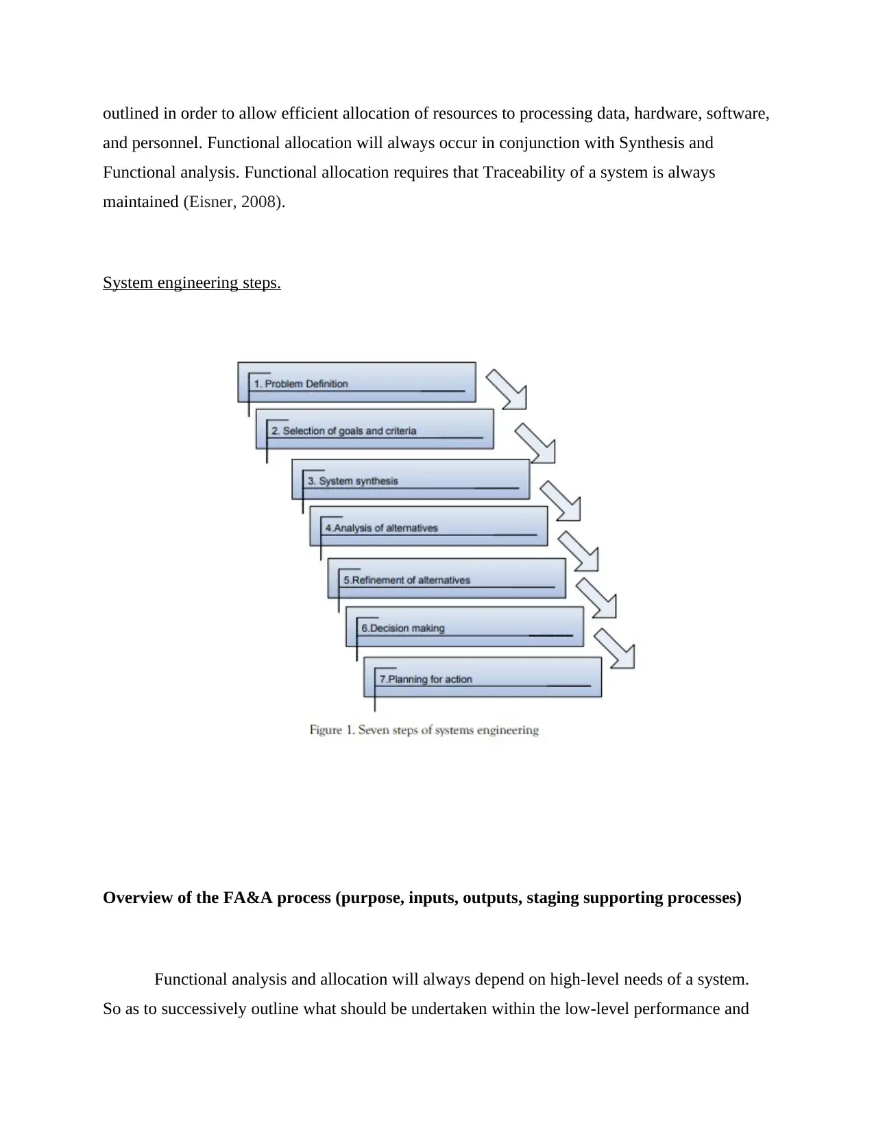
System engineering steps.
Overview of the FA&A process (purpose, inputs, outputs, staging supporting processes)
Functional analysis and allocation will always depend on high-level needs of a system.
So as to successively outline what should be undertaken within the low-level performance and
and personnel. Functional allocation will always occur in conjunction with Synthesis and
Functional analysis. Functional allocation requires that Traceability of a system is always
maintained (Eisner, 2008).
System engineering steps.
Overview of the FA&A process (purpose, inputs, outputs, staging supporting processes)
Functional analysis and allocation will always depend on high-level needs of a system.
So as to successively outline what should be undertaken within the low-level performance and
⊘ This is a preview!⊘
Do you want full access?
Subscribe today to unlock all pages.
Trusted by 1+ million students worldwide
functional requirements, functional analysis and allocation processes will always need to be
iterated. This enables architectures to be intensively defined to the last detail. The criteria for
supporting system designs that are integrated will depend on the extent of definition and
allocation of system requirements. The following approach is taken when translating systems
requirements at a particular level so that they can fit a specific performance and functional
design (Simões, et al., 2012).
Definition of functional terms associated with a system then breaking down upper level
functions into smaller stages. This makes it easy to identify what can successively be done at the
lower levels by the system.
Translation of top-level performance needs to detailed performance and functional design
constraints/designs. This allows the operation ability of functions to be well outlined.
Identification of functional grouping as this allows minimization of control interfaces.
This is normally known as functional partitioning.
Examination of life cycle functions. This includes the eight primary functionalities that
may relate to a particular system.
Functional Partitioning
It allows functions to be grouped logically that they fit with elements that will be used.
This helps to lower functional interfaces. Partitioning is undertaken in part with functional
decomposition. Partitioning enables identification of functions that allow modular components to
be employed when designing open systems. Partitioning also allows the integrability of available
equipment to be analyzed so as to understand how well it can perform with available systems
(Leveson & Weiss, 2009).
Requirements Loop
During functional analysis and allocation, re-check of previous requirements will always
have to be undertaken. This exists due to functional issues emergence, which normally requires
re-examination of top-level system requirements. Issues normally emerge when incompatible
requirements are brought together, or functional conflict.
FUNCTIONAL ARCHITECTURE
Paraphrase This Document
Need a fresh take? Get an instant paraphrase of this document with our AI Paraphraser
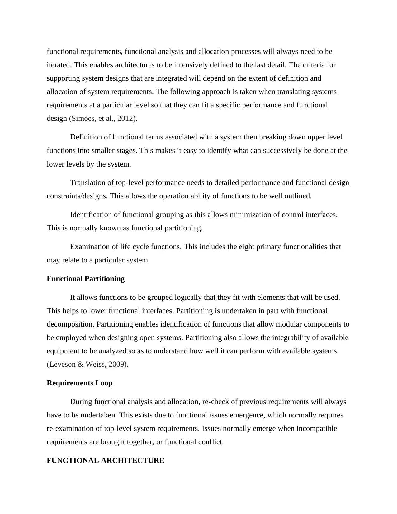
This is a top-bottom breakdown of the functional and performance needs of a system. the
Architecture outlays the logical arrangement of functions, performance needs associated with the
particular system, and functions that always need to be performed (Shyrokau, et al., 2013).
Functional Analysis and allocation normally produce a functional architecture that constitutes
detailed package documentation that will assist in analyzing functions and allocation of systems
requirements. The systems architecture will constitute an IDEFO diagram, timeline sheet,
requirement allocation sheet, and flow block diagram. Also included will be the documentation
needed to describe the functional aspects of a system.
Functional Architecture example
Supporting Stage Processes
FUNCTIONAL FLOW BLOCK DIAGRAM (FFBD)
This allows the description of systems requirements using functional terms. The FFBD is
designed to ensure:
Life Cycle functions are well covered.
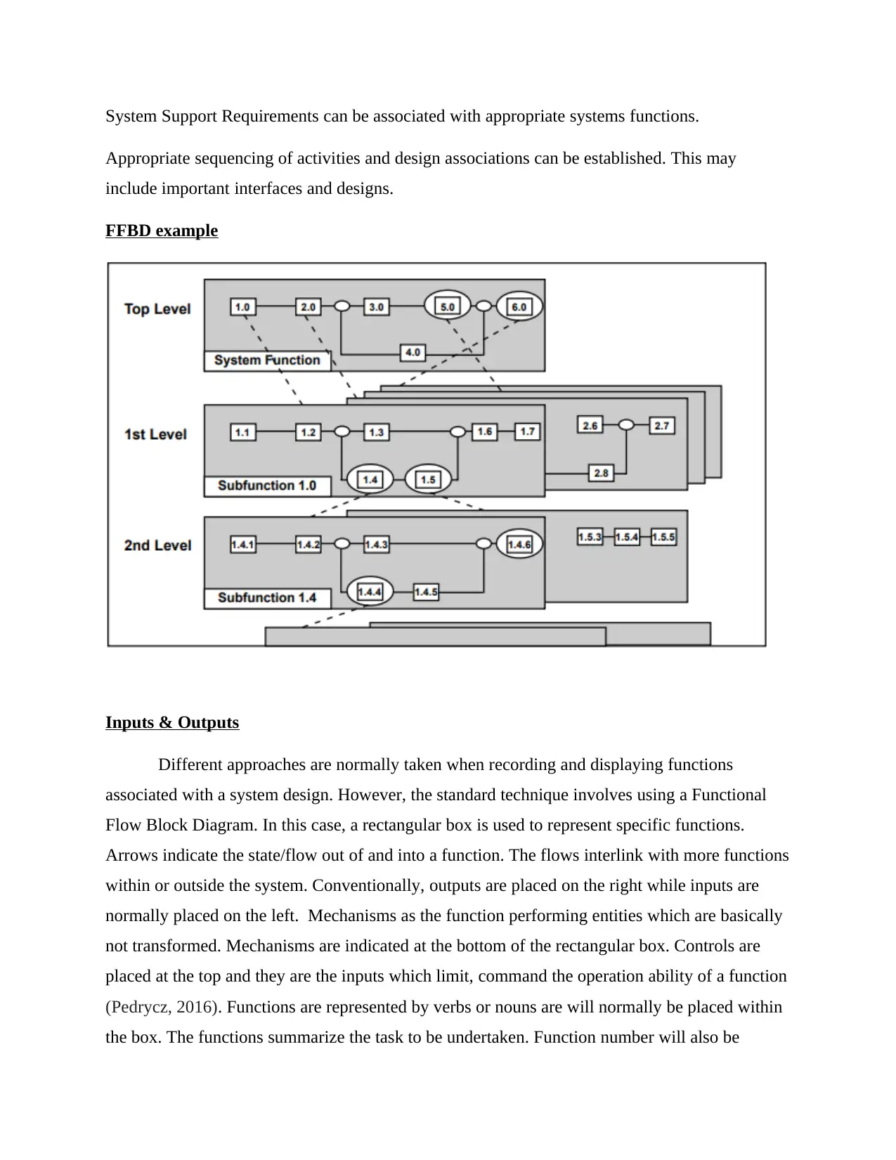
System Support Requirements can be associated with appropriate systems functions.
Appropriate sequencing of activities and design associations can be established. This may
include important interfaces and designs.
FFBD example
Inputs & Outputs
Different approaches are normally taken when recording and displaying functions
associated with a system design. However, the standard technique involves using a Functional
Flow Block Diagram. In this case, a rectangular box is used to represent specific functions.
Arrows indicate the state/flow out of and into a function. The flows interlink with more functions
within or outside the system. Conventionally, outputs are placed on the right while inputs are
normally placed on the left. Mechanisms as the function performing entities which are basically
not transformed. Mechanisms are indicated at the bottom of the rectangular box. Controls are
placed at the top and they are the inputs which limit, command the operation ability of a function
(Pedrycz, 2016). Functions are represented by verbs or nouns are will normally be placed within
the box. The functions summarize the task to be undertaken. Function number will also be
⊘ This is a preview!⊘
Do you want full access?
Subscribe today to unlock all pages.
Trusted by 1+ million students worldwide
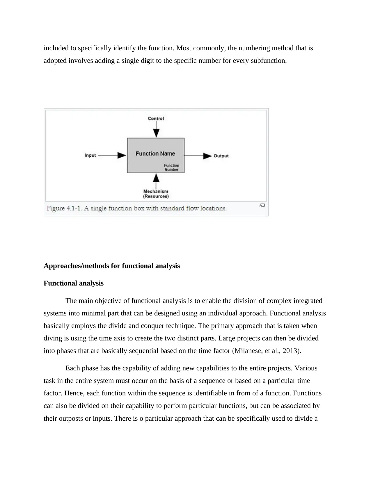
included to specifically identify the function. Most commonly, the numbering method that is
adopted involves adding a single digit to the specific number for every subfunction.
Approaches/methods for functional analysis
Functional analysis
The main objective of functional analysis is to enable the division of complex integrated
systems into minimal part that can be designed using an individual approach. Functional analysis
basically employs the divide and conquer technique. The primary approach that is taken when
diving is using the time axis to create the two distinct parts. Large projects can then be divided
into phases that are basically sequential based on the time factor (Milanese, et al., 2013).
Each phase has the capability of adding new capabilities to the entire projects. Various
task in the entire system must occur on the basis of a sequence or based on a particular time
factor. Hence, each function within the sequence is identifiable in from of a function. Functions
can also be divided on their capability to perform particular functions, but can be associated by
their outposts or inputs. There is o particular approach that can be specifically used to divide a
Paraphrase This Document
Need a fresh take? Get an instant paraphrase of this document with our AI Paraphraser
function, as this will normally depend upon the particular design and the appropriate functional
breakdown.
Function and Flow Numbers
A flow or function in a system is used to identify flows within a systems design. The
number are normally meant to be highly unique and constitute a number of components that have
letters and numbers separated using periods. Components normally represent a system design
hierarchical level. In most cases, more than normally functions are normally used to provide
room for upcoming design variations, which might also need higher levels to be developed
without necessarily having to renumber other components. Renumbering can lead to confusion
and creates extra work (Van Lamsweerde, 2009).
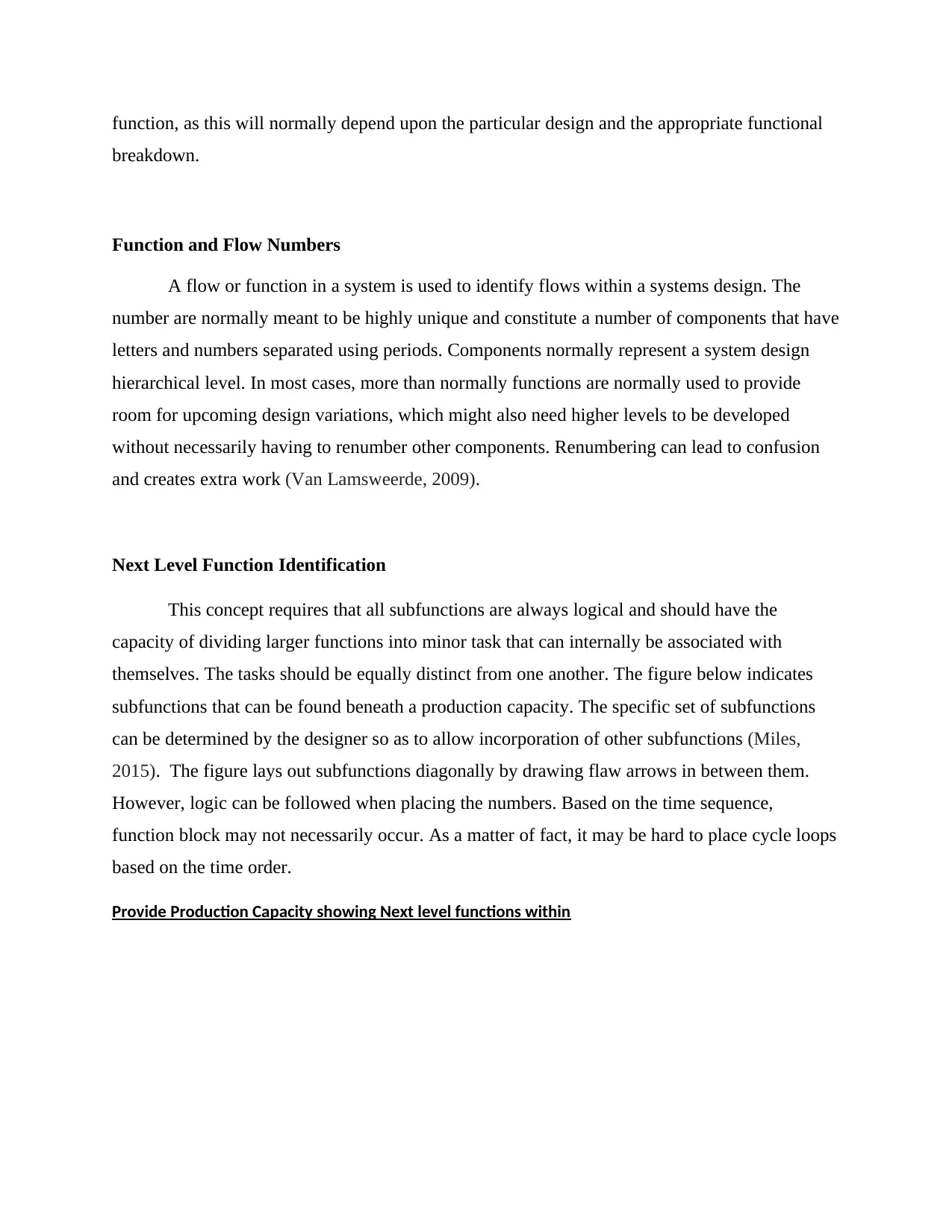
Next Level Function Identification
This concept requires that all subfunctions are always logical and should have the
capacity of dividing larger functions into minor task that can internally be associated with
themselves. The tasks should be equally distinct from one another. The figure below indicates
subfunctions that can be found beneath a production capacity. The specific set of subfunctions
can be determined by the designer so as to allow incorporation of other subfunctions (Miles,
2015). The figure lays out subfunctions diagonally by drawing flaw arrows in between them.
However, logic can be followed when placing the numbers. Based on the time sequence,
function block may not necessarily occur. As a matter of fact, it may be hard to place cycle loops
based on the time order.
Provide Production Capacity showing Next level functions within
breakdown.
Function and Flow Numbers
A flow or function in a system is used to identify flows within a systems design. The
number are normally meant to be highly unique and constitute a number of components that have
letters and numbers separated using periods. Components normally represent a system design
hierarchical level. In most cases, more than normally functions are normally used to provide
room for upcoming design variations, which might also need higher levels to be developed
without necessarily having to renumber other components. Renumbering can lead to confusion
and creates extra work (Van Lamsweerde, 2009).
Next Level Function Identification
This concept requires that all subfunctions are always logical and should have the
capacity of dividing larger functions into minor task that can internally be associated with
themselves. The tasks should be equally distinct from one another. The figure below indicates
subfunctions that can be found beneath a production capacity. The specific set of subfunctions
can be determined by the designer so as to allow incorporation of other subfunctions (Miles,
2015). The figure lays out subfunctions diagonally by drawing flaw arrows in between them.
However, logic can be followed when placing the numbers. Based on the time sequence,
function block may not necessarily occur. As a matter of fact, it may be hard to place cycle loops
based on the time order.
Provide Production Capacity showing Next level functions within
Output Matrix
This is an approach that can be used to display function flows. The method is appropriate
where using very many arrows would lead to confusion. Functions are placed on a diagonal grid.
Grid rectangles placed above the diagonal represent function flow on a similar row but left of a
function within a particular column. Rectangles within a diagonal represent a reverse flow from a
particular function based on a row pointing directly to the function within a specific column. The
grid approach is not usually suitable in indicating the relationship between mechanism inputs and
controls.
⊘ This is a preview!⊘
Do you want full access?
Subscribe today to unlock all pages.
Trusted by 1+ million students worldwide
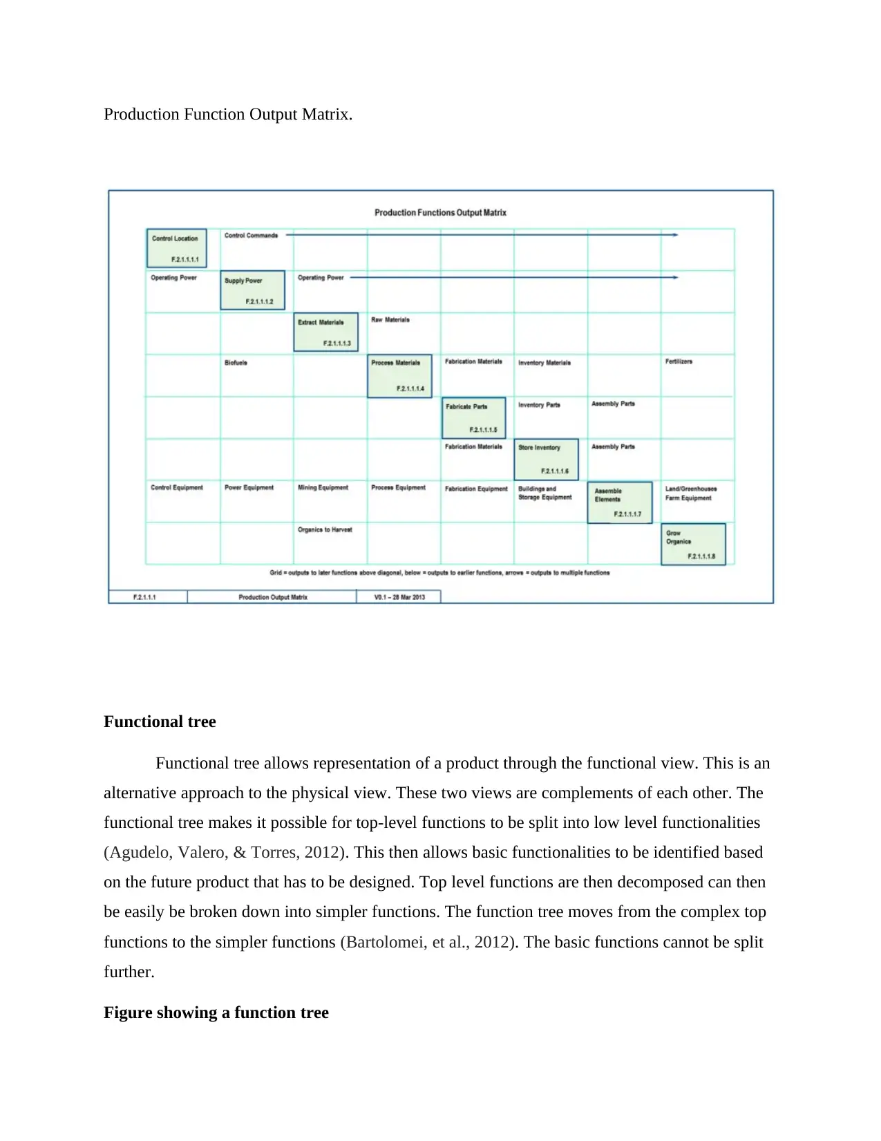
Production Function Output Matrix.
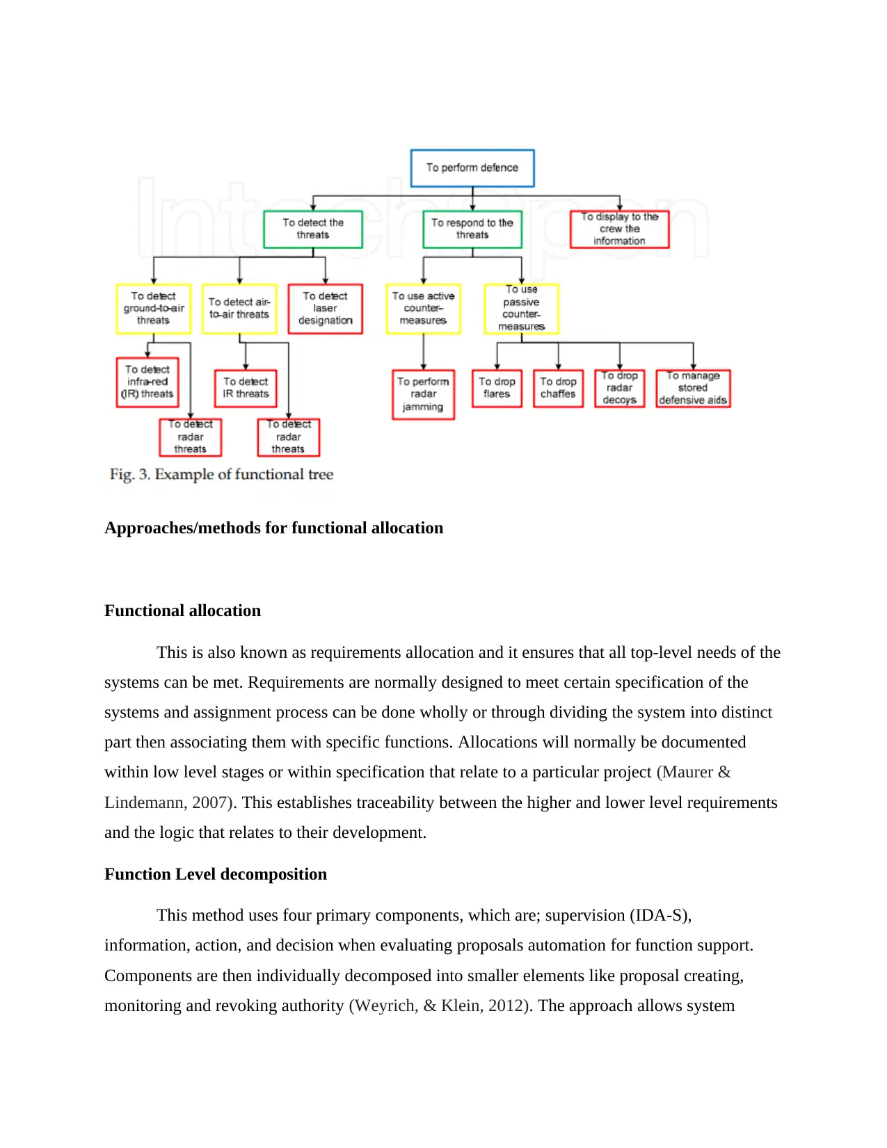
Functional tree
Functional tree allows representation of a product through the functional view. This is an
alternative approach to the physical view. These two views are complements of each other. The
functional tree makes it possible for top-level functions to be split into low level functionalities
(Agudelo, Valero, & Torres, 2012). This then allows basic functionalities to be identified based
on the future product that has to be designed. Top level functions are then decomposed can then
be easily be broken down into simpler functions. The function tree moves from the complex top
functions to the simpler functions (Bartolomei, et al., 2012). The basic functions cannot be split
further.
Figure showing a function tree
Paraphrase This Document
Need a fresh take? Get an instant paraphrase of this document with our AI Paraphraser
Approaches/methods for functional allocation
Functional allocation
This is also known as requirements allocation and it ensures that all top-level needs of the
systems can be met. Requirements are normally designed to meet certain specification of the
systems and assignment process can be done wholly or through dividing the system into distinct
part then associating them with specific functions. Allocations will normally be documented
within low level stages or within specification that relate to a particular project (Maurer &
Lindemann, 2007). This establishes traceability between the higher and lower level requirements
and the logic that relates to their development.
Function Level decomposition
This method uses four primary components, which are; supervision (IDA-S),
information, action, and decision when evaluating proposals automation for function support.
Components are then individually decomposed into smaller elements like proposal creating,
monitoring and revoking authority (Weyrich, & Klein, 2012). The approach allows system
engineers to ask questions such as, is a function entirely dependent upon automation-based
data/information or is it reliant on the human based aspects of environment monitoring? Answers
associated with such questions make it possible to identify various work articulations that a
critical towards the development of a system.
Conclusion
The practical and Technological co-evolution can occur due to the need of bridging the
gap between practice and technology. More importantly, occurrence of co-evolution may be
motivated by the need to eliminate dilemma that stem from conflict of interest. Co-evolution
tends to curtail approaches that can be employed in function allocation. For instance, it is
common for system engineers to workload can be employed in analyzing various Function
Allocation approaches. However, if the decision-making approach in Functional Allocation is
used in conjunction with rich representations of a similar context, such dilemmas will easily be
eliminated (Parnell, et al., 2011).
Functional analysis, on the other hand, is highly critical in systems engineering. As a tool
of guiding how new products can be developed. Functional analysis ensures intensive evaluation
of how the new product can be developed through fostering optional solutions, thereby,
eliminating the chance of failing to incorporate critical options. Thereby, it helps establish clear
associations between physical components and future products that will be developed. This
makes it essential for system engineers to learn the application of functional analysis and
allocation in exploring new concepts.
⊘ This is a preview!⊘
Do you want full access?
Subscribe today to unlock all pages.
Trusted by 1+ million students worldwide
1 out of 15
Related Documents


Your All-in-One AI-Powered Toolkit for Academic Success.
+13062052269
info@desklib.com
Available 24*7 on WhatsApp / Email
![[object Object]](/_next/static/media/star-bottom.7253800d.svg)
Unlock your academic potential
Copyright © 2020–2026 A2Z Services. All Rights Reserved. Developed and managed by ZUCOL.