Functional Analysis and Allocation in System Engineering Design Review
VerifiedAdded on 2023/04/04
|13
|2728
|303
Report
AI Summary
This report provides a critical review of Functional Analysis and Allocation (FA&A) in system engineering design. It examines the purpose, inputs, outputs, and staging of the FA&A process within the system life cycle. The report delves into various approaches and methods for performing both functional analysis, including Functional Flow Block Diagrams, time representation, and output matrices, and functional allocation, such as decomposing functions to lower levels and establishing functional architecture. The analysis covers traceability, requirement allocation, and the use of functional diagrams. The document concludes by summarizing the key aspects of FA&A and its importance in translating system requirements into detailed design criteria. Desklib offers this and many other solved assignments for students.
System Engineering Design 1
FUNCTIONAL ANALYSIS AND ALLOCATION
By Name
Course
Instructor
Institution
Location
Date
FUNCTIONAL ANALYSIS AND ALLOCATION
By Name
Course
Instructor
Institution
Location
Date
Paraphrase This Document
Need a fresh take? Get an instant paraphrase of this document with our AI Paraphraser
System Engineering Design 2
Table of Contents
INTRODUCTION...........................................................................................................................................2
OVERVIEW...................................................................................................................................................2
Purpose...................................................................................................................................................2
Inputs.......................................................................................................................................................3
Outputs....................................................................................................................................................3
Staging.....................................................................................................................................................3
Supporting Processes..............................................................................................................................4
FUNCTIONAL ANALYSIS METHODS..............................................................................................................4
Functional Flow Block Diagram................................................................................................................4
Time Representation...........................................................................................................................6
Functional relationship representation...............................................................................................6
Flow Arrows.........................................................................................................................................7
Top-level diagram................................................................................................................................7
Analysis....................................................................................................................................................7
Flow and Function Numbers................................................................................................................7
Output Matrix......................................................................................................................................7
FUNCTIONAL ALLOCATION..........................................................................................................................8
Decompose to Lower-Level Functions.....................................................................................................8
Functional Architecture...........................................................................................................................9
Allocate Performance to All Functional Levels.........................................................................................9
CONCLUSION.............................................................................................................................................10
BIBLIOGRAPHY...........................................................................................................................................11
System Engineering Design 3
INTRODUCTION
This report is about Functional Analysis and Allocation in a systems engineering design through
evaluation of supporting processes, staging, outputs, inputs, purpose, and process of Functional
Analysis and Allocation. Functional Analysis and Allocation also abbreviated as FA&A can be
defined as a process of translating the requirement levels of a system into detailed performance
and functional design criteria. The system engineering design is a recursive, iterative, and
comprehensive problem-solving process used top-down sequentially by the integrated team
(Perry, et al., 2016). This process transforms the requirements and needs into a set of system
process and product descriptions, provides input for the next development level, and produce
information for decision-makers.
The FA&A process includes inputs and outputs, staging the process within the system life-cycle,
and methods or approaches for performing allocation and analysis. The FA&A process bridges
the gap between the constraints and requirements of high-level system set and the detailed
required set to purchase or develop and implement programs (Bijan, et al., 2012). This process is
an integral part of both the design loop and the requirement loop.
OVERVIEW
Purpose
Functional Analysis and Allocation enables for a better understanding of what the engineering
system has to perform, how it is going to be performed, the extent of the performance, the
conflicts and priorities related with the functions at a lower level (Alsaleh & Haron, 2016). The
FA&A provides information significant to the optimization of physical solutions.
Inputs
The FA&A process inputs majorly consist of the project constraints, requirements, objectives,
and needs of the customer. The process inputs may include requirements based on corporate
⊘ This is a preview!⊘
Do you want full access?
Subscribe today to unlock all pages.
Trusted by 1+ million students worldwide
System Engineering Design 4
knowledge, program decision requirement, output requirements from prior applications of the
system engineering process application, available technology base, environmental, measures of
effectiveness, and missions (Anyaeche & Oluleye, 2011).
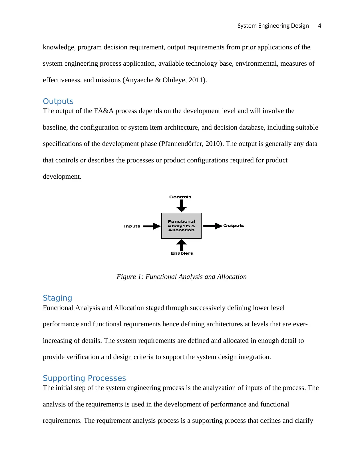
Outputs
The output of the FA&A process depends on the development level and will involve the
baseline, the configuration or system item architecture, and decision database, including suitable
specifications of the development phase (Pfannendörfer, 2010). The output is generally any data
that controls or describes the processes or product configurations required for product
development.
Figure 1: Functional Analysis and Allocation
Staging
Functional Analysis and Allocation staged through successively defining lower level
performance and functional requirements hence defining architectures at levels that are ever-
increasing of details. The system requirements are defined and allocated in enough detail to
provide verification and design criteria to support the system design integration.
Supporting Processes
The initial step of the system engineering process is the analyzation of inputs of the process. The
analysis of the requirements is used in the development of performance and functional
requirements. The requirement analysis process is a supporting process that defines and clarify
knowledge, program decision requirement, output requirements from prior applications of the
system engineering process application, available technology base, environmental, measures of
effectiveness, and missions (Anyaeche & Oluleye, 2011).
Outputs
The output of the FA&A process depends on the development level and will involve the
baseline, the configuration or system item architecture, and decision database, including suitable
specifications of the development phase (Pfannendörfer, 2010). The output is generally any data
that controls or describes the processes or product configurations required for product
development.
Figure 1: Functional Analysis and Allocation
Staging
Functional Analysis and Allocation staged through successively defining lower level
performance and functional requirements hence defining architectures at levels that are ever-
increasing of details. The system requirements are defined and allocated in enough detail to
provide verification and design criteria to support the system design integration.
Supporting Processes
The initial step of the system engineering process is the analyzation of inputs of the process. The
analysis of the requirements is used in the development of performance and functional
requirements. The requirement analysis process is a supporting process that defines and clarify
Paraphrase This Document
Need a fresh take? Get an instant paraphrase of this document with our AI Paraphraser
System Engineering Design 5
the design constraints and functional requirements (Smith & Castro, 2018). Functional
partitioning is also a supporting process which involves grouping of functions that fit with the
components to be used logically and reduce functional interfaces.
FUNCTIONAL ANALYSIS METHODS
The next step of Systems Engineering Design after setting the requirements and goals of the
system is functional analysis. Functional analysis distributes an engineering system design into
small sections known as functional elements which illustrates what each part will perform. At
this stage, there is no need for limiting the choices of the design since the perfect solutions or
choices may be left out. The approaches or methods for functional analysis include the analysis
process and functional diagrams.
Functional Flow Block Diagram
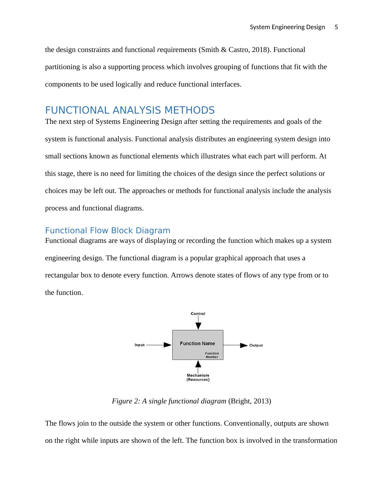
Functional diagrams are ways of displaying or recording the function which makes up a system
engineering design. The functional diagram is a popular graphical approach that uses a
rectangular box to denote every function. Arrows denote states of flows of any type from or to
the function.
Figure 2: A single functional diagram (Bright, 2013)
The flows join to the outside the system or other functions. Conventionally, outputs are shown
on the right while inputs are shown of the left. The function box is involved in the transformation
the design constraints and functional requirements (Smith & Castro, 2018). Functional
partitioning is also a supporting process which involves grouping of functions that fit with the
components to be used logically and reduce functional interfaces.
FUNCTIONAL ANALYSIS METHODS
The next step of Systems Engineering Design after setting the requirements and goals of the
system is functional analysis. Functional analysis distributes an engineering system design into
small sections known as functional elements which illustrates what each part will perform. At
this stage, there is no need for limiting the choices of the design since the perfect solutions or
choices may be left out. The approaches or methods for functional analysis include the analysis
process and functional diagrams.
Functional Flow Block Diagram
Functional diagrams are ways of displaying or recording the function which makes up a system
engineering design. The functional diagram is a popular graphical approach that uses a
rectangular box to denote every function. Arrows denote states of flows of any type from or to
the function.
Figure 2: A single functional diagram (Bright, 2013)
The flows join to the outside the system or other functions. Conventionally, outputs are shown
on the right while inputs are shown of the left. The function box is involved in the transformation
System Engineering Design 6
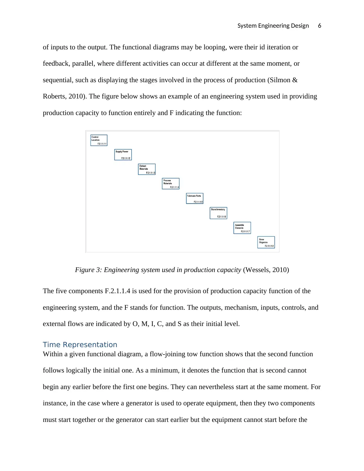
of inputs to the output. The functional diagrams may be looping, were their id iteration or
feedback, parallel, where different activities can occur at different at the same moment, or
sequential, such as displaying the stages involved in the process of production (Silmon &
Roberts, 2010). The figure below shows an example of an engineering system used in providing
production capacity to function entirely and F indicating the function:
Figure 3: Engineering system used in production capacity (Wessels, 2010)
The five components F.2.1.1.4 is used for the provision of production capacity function of the
engineering system, and the F stands for function. The outputs, mechanism, inputs, controls, and
external flows are indicated by O, M, I, C, and S as their initial level.
Time Representation
Within a given functional diagram, a flow-joining tow function shows that the second function
follows logically the initial one. As a minimum, it denotes the function that is second cannot
begin any earlier before the first one begins. They can nevertheless start at the same moment. For
instance, in the case where a generator is used to operate equipment, then they two components
must start together or the generator can start earlier but the equipment cannot start before the
⊘ This is a preview!⊘
Do you want full access?
Subscribe today to unlock all pages.
Trusted by 1+ million students worldwide
System Engineering Design 7
generator (Ferrari, et al., 2010). In some cases, numerous function boxes denote a strict order of
time, where a single has to be completed before the following one begins, but this is only
suitable when flows involve similar items.
In case there is a loop in the functional diagram, the sequence of start should be accounted for in
the system engineering design. For example, in the water treatment unit that dirty water is
channelled in from residents and channel back the clean water. Different time representation is
needed when the entire system evolves from a single phase to another, and novel flows and
functional element are added. This can be done by preparing different versions of similar
diagrams for every phase and making the new items that were not existing in the earlier phase.
Functional relationship representation
Diagrams of the higher level normally have more flows since they are representing numerous
systems at once. This complexity can be handled is by using large drawings with numerous
sheets such that every sheet shows only a subset of the flows to similar function, to make them
more understandable. The complexity can also be dealt with through tracking the flows in data
tables and spreadsheet, which may have numerous entries as required, a single for every flow.
Whichever approach is used in tracking or displaying the flows and function, they denote similar
relationships between system parts.
Flow Arrows
Flow arrows denote a movement of any kind of resource or a state of an item between functions.
The casting of a raw metal from the process of foundry and a machined section made from the
casting are different states of the section being produced. The mentioned part would be output
and the casting would be the input. The resources such as human labour and energy which are
used as inputs or made as outputs from functions. Flows may merge and divide between
terminals, but be understood that both the junction sides are equal.
Paraphrase This Document
Need a fresh take? Get an instant paraphrase of this document with our AI Paraphraser
System Engineering Design 8
Top-level diagram
During an engineering system design, the major concern is normally concerned with the
production function. There can be a difference in the placement of the system boundary for
analysis and design purposes. The outputs and inputs from the external system boundary selected
as portrayed to the right and left of the diagram, and are divided by part. Showing all the project
details at once in one diagram makes it too complicated and large. Instead, the complex diagram
can be minimized through presenting numerous detail levels, where a box at a single level
denotes many detailed diagrams at the following level.
Analysis
Flow and Function Numbers
A number and a name are what classifies a given flow or function within a system design. The
numbers are expected to be unique and are made of numerous components, each possessing
letters and numbers, which are separated by periods. The components denote hierarchy levels in
the design of the system.
Output Matrix
This method works in case there are numerous arrows which may be confusing. The individual
functions are positioned on the grid diagonal. Rectangles beneath the diagonal show an opposite
flow from the function in a similar row on the right back to the function in a specific column on
top. (Capilla, et al., 2011)The method of the grid is not suitable at indicating outputs that return
to the same function as they begin, or the mechanism and control input relationship.
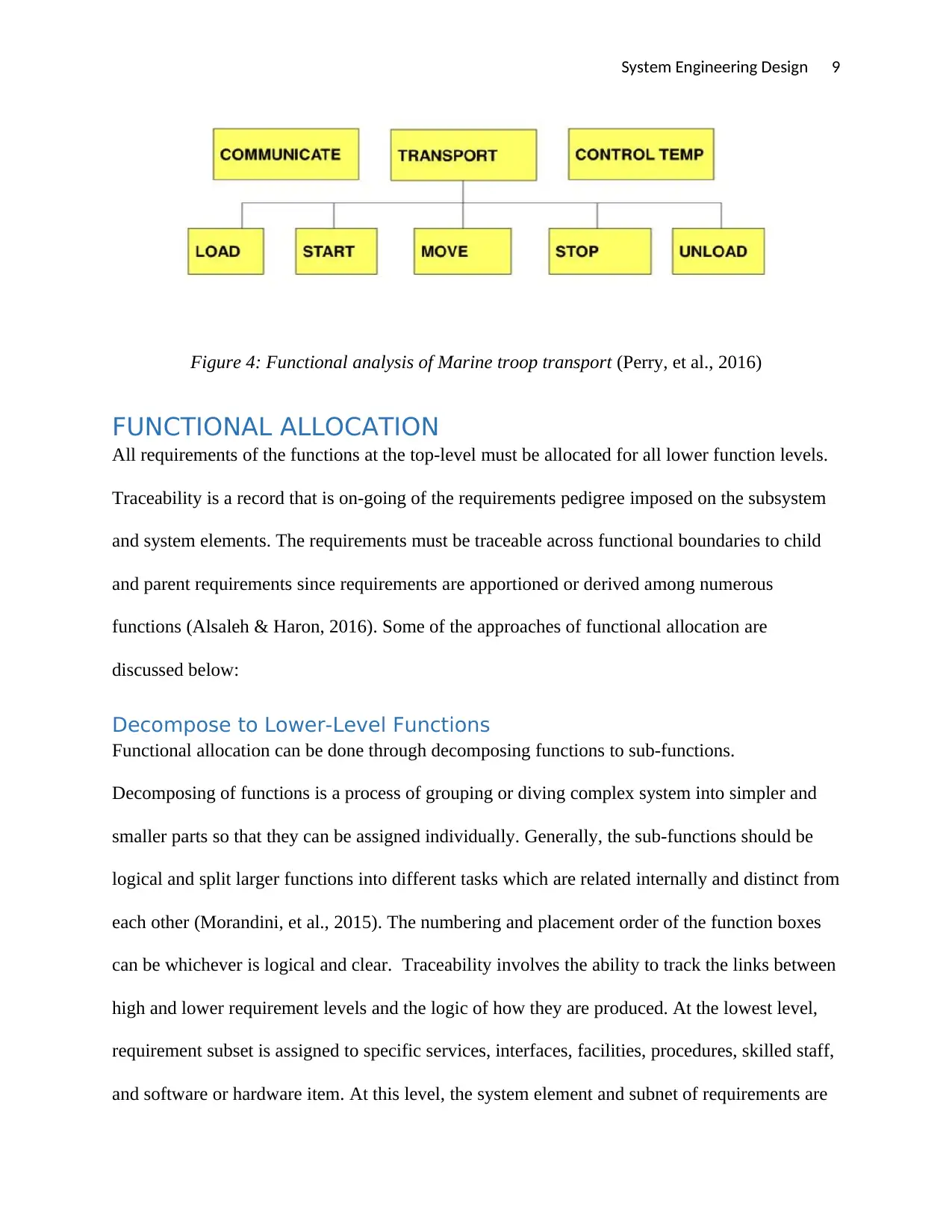
An example of Functional Analysis is Marine Troop Transport Requirements where corps are
required to transport troops in squad level units at a distance of 50k within 90 min. The action
verbs are control temp, transport, and communicate while sub functions are load, start, move,
stop, unload. The Functional Architecture will be:
Top-level diagram
During an engineering system design, the major concern is normally concerned with the
production function. There can be a difference in the placement of the system boundary for
analysis and design purposes. The outputs and inputs from the external system boundary selected
as portrayed to the right and left of the diagram, and are divided by part. Showing all the project
details at once in one diagram makes it too complicated and large. Instead, the complex diagram
can be minimized through presenting numerous detail levels, where a box at a single level
denotes many detailed diagrams at the following level.
Analysis
Flow and Function Numbers
A number and a name are what classifies a given flow or function within a system design. The
numbers are expected to be unique and are made of numerous components, each possessing
letters and numbers, which are separated by periods. The components denote hierarchy levels in
the design of the system.
Output Matrix
This method works in case there are numerous arrows which may be confusing. The individual
functions are positioned on the grid diagonal. Rectangles beneath the diagonal show an opposite
flow from the function in a similar row on the right back to the function in a specific column on
top. (Capilla, et al., 2011)The method of the grid is not suitable at indicating outputs that return
to the same function as they begin, or the mechanism and control input relationship.
An example of Functional Analysis is Marine Troop Transport Requirements where corps are
required to transport troops in squad level units at a distance of 50k within 90 min. The action
verbs are control temp, transport, and communicate while sub functions are load, start, move,
stop, unload. The Functional Architecture will be:
System Engineering Design 9
Figure 4: Functional analysis of Marine troop transport (Perry, et al., 2016)
FUNCTIONAL ALLOCATION
All requirements of the functions at the top-level must be allocated for all lower function levels.
Traceability is a record that is on-going of the requirements pedigree imposed on the subsystem
and system elements. The requirements must be traceable across functional boundaries to child
and parent requirements since requirements are apportioned or derived among numerous
functions (Alsaleh & Haron, 2016). Some of the approaches of functional allocation are
discussed below:
Decompose to Lower-Level Functions
Functional allocation can be done through decomposing functions to sub-functions.
Decomposing of functions is a process of grouping or diving complex system into simpler and
smaller parts so that they can be assigned individually. Generally, the sub-functions should be
logical and split larger functions into different tasks which are related internally and distinct from
each other (Morandini, et al., 2015). The numbering and placement order of the function boxes
can be whichever is logical and clear. Traceability involves the ability to track the links between
high and lower requirement levels and the logic of how they are produced. At the lowest level,
requirement subset is assigned to specific services, interfaces, facilities, procedures, skilled staff,
and software or hardware item. At this level, the system element and subnet of requirements are
⊘ This is a preview!⊘
Do you want full access?
Subscribe today to unlock all pages.
Trusted by 1+ million students worldwide
System Engineering Design 10
simple enough to actually design for. In the case of a complex project, software tools can be used
for the tracing process and function allocation (Xing & Zeng, 2014).
Functional Architecture
The functional architecture involves a top-down system decomposition of the performance
requirements and system function. The functional architecture shows the allocation of functions
that should be performed and also the logical sequence of the performance and function
requirements related to the function. This architecture involves the functional description of the
government-furnished an existing items to be used in the system (Reid, 212). The functional
architecture generated by the allocation process and functional analysis is the detailed
documentation package established to allocate the performance needed. It includes requirement
allocation sheet, timeline sheets, and functional flow block diagrams.
Functional diagrams are ways of displaying or recording the function which makes up a system
engineering design. The functional diagram is a popular graphical approach that uses a
rectangular box to denote every function. Arrows denote states of flows of any type from or to
the function. The flows join to the outside the system or other functions. Conventionally, outputs
are shown on the right while inputs are shown of the left. The function box is involved in the
transformation of inputs to the output (Selva, et al., 2016). The functional diagrams may be
looping, were their id iteration or feedback, parallel, where different activities can occur at
different at the same moment, or sequential, such as displaying the stages involved in the process
of production.
Allocate Performance to All Functional Levels
The functional allocation can also be attained through performance allocation to all functional
levels so as to ensure that all the top level requirements are attained. This is achieved through
Paraphrase This Document
Need a fresh take? Get an instant paraphrase of this document with our AI Paraphraser
System Engineering Design 11
assigning single or numerous functions to all function levels for implementation. The allocated
functions may be an entire requirement or diving the requirement into parts and then assigning
the parts to separate functional levels. Other parameters such as time limits are also passed down
to all the functional levels (Kumar & Suresh, 2018). For an engineering system, the requirements
may be allocated in section in the form of structural functions, propulsion system, or
maintenance system.
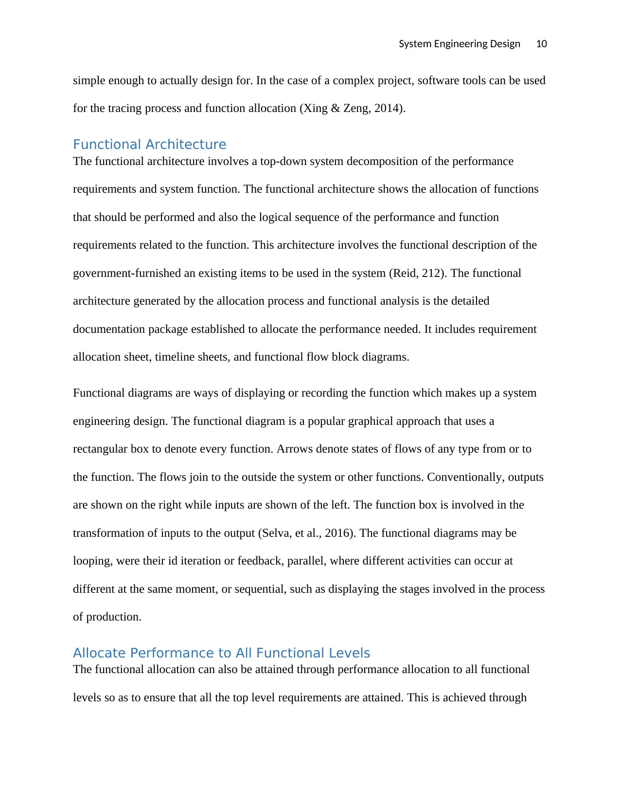
For the examples of Marine Troop Transport explained in figure 4 above, the functional
allocation can be determined from the functional architecture. The allocation requirements is
within 90 minutes, and derived requirements is expected speed of 42km/h: The figure below
shows the functional allocation of the marine troop system:
Figure 5: Functional allocation of marine troop transport (Perry, et al., 2016)
CONCLUSION
Functional Analysis and Allocation in a Systems engineering project a process of translating the
requirement levels of a system into detailed performance and functional design criteria. The
purpose of FA&A process is to provide an increased level of descriptive details of the processes
and products with every system engineering process application. The major focus of this report
includes an evaluation of supporting processes, staging, outputs, inputs, purpose, and process of
assigning single or numerous functions to all function levels for implementation. The allocated
functions may be an entire requirement or diving the requirement into parts and then assigning
the parts to separate functional levels. Other parameters such as time limits are also passed down
to all the functional levels (Kumar & Suresh, 2018). For an engineering system, the requirements
may be allocated in section in the form of structural functions, propulsion system, or
maintenance system.
For the examples of Marine Troop Transport explained in figure 4 above, the functional
allocation can be determined from the functional architecture. The allocation requirements is
within 90 minutes, and derived requirements is expected speed of 42km/h: The figure below
shows the functional allocation of the marine troop system:
Figure 5: Functional allocation of marine troop transport (Perry, et al., 2016)
CONCLUSION
Functional Analysis and Allocation in a Systems engineering project a process of translating the
requirement levels of a system into detailed performance and functional design criteria. The
purpose of FA&A process is to provide an increased level of descriptive details of the processes
and products with every system engineering process application. The major focus of this report
includes an evaluation of supporting processes, staging, outputs, inputs, purpose, and process of
System Engineering Design 12
Functional Analysis and Allocation. Some of the significance of FA&A process include enable
traceability of process and product design requirements, erasure attainability, desirability,
consistency, and validity of customer requirements on the resulting performance and functional
requirements, and also provide solution alternative decisions after customer requirements, life
cycle resources, and system effectiveness have been evaluated.
BIBLIOGRAPHY
Alsaleh, S. & Haron, H., 2016. he Most Important Functional and Non-Functional Requirements of
Knowledge Sharing System at Public Academic Institutions: A Case Study. Lecture Notes on Software
Engineering, Volume 4, pp. 157-161.
Anyaeche, C. & Oluleye, A., 2011. A PRODUCTIVITY EVALUATION MODEL BASED ON INPUT AND OUTPUT
ORIENTATIONS. The South African Journal of Industrial Engineering, Volume 20.
Bijan, Y., Stracener, J. & Woods, T., 2012. Systems requirements engineering-State of the methodology.
Systems Engineering, Volume 16, pp. 267-276.
⊘ This is a preview!⊘
Do you want full access?
Subscribe today to unlock all pages.
Trusted by 1+ million students worldwide
1 out of 13
Related Documents


Your All-in-One AI-Powered Toolkit for Academic Success.
+13062052269
info@desklib.com
Available 24*7 on WhatsApp / Email
![[object Object]](/_next/static/media/star-bottom.7253800d.svg)
Unlock your academic potential
Copyright © 2020–2026 A2Z Services. All Rights Reserved. Developed and managed by ZUCOL.