Report on Gas Conversion Process and Safety Instrumented Systems (SIS)
VerifiedAdded on  2022/10/09
|8
|1680
|414
Report
AI Summary
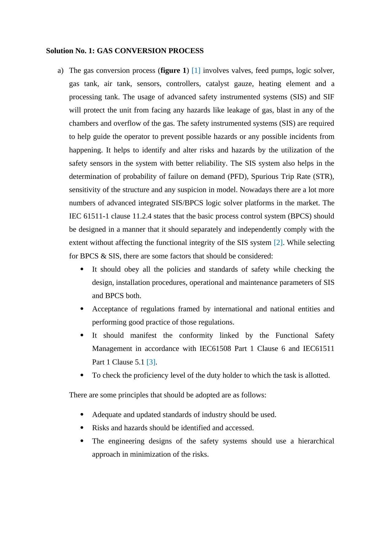
This report provides a comprehensive analysis of a gas conversion process, focusing on the implementation of safety instrumented systems (SIS). It details the components involved, including valves, sensors, and controllers, and emphasizes the importance of SIS in preventing hazards such as gas leaks, explosions, and temperature-related issues. The report explores the integration of SIS with the basic process control system (BPCS) and adheres to IEC 61511 and 61508 standards. It covers functional safety management (FSM), risk assessment methodologies like HAZID and LOPA, and the development of safety requirements specifications (SRS). The report also includes a responsibility matrix for FSM and discusses the application of functional safety standards across various sectors, offering a practical approach to ensuring process safety and reliability. It also provides the components of Functional Safety Management Plan and the responsibility matrix of FSMP.

Solution No. 1: GAS CONVERSION PROCESS
a) The gas conversion process (figure 1) [1] involves valves, feed pumps, logic solver,
gas tank, air tank, sensors, controllers, catalyst gauze, heating element and a
processing tank. The usage of advanced safety instrumented systems (SIS) and SIF
will protect the unit from facing any hazards like leakage of gas, blast in any of the
chambers and overflow of the gas. The safety instrumented systems (SIS) are required
to help guide the operator to prevent possible hazards or any possible incidents from
happening. It helps to identify and alter risks and hazards by the utilization of the
safety sensors in the system with better reliability. The SIS system also helps in the
determination of probability of failure on demand (PFD), Spurious Trip Rate (STR),
sensitivity of the structure and any suspicion in model. Nowadays there are a lot more
numbers of advanced integrated SIS/BPCS logic solver platforms in the market. The
IEC 61511-1 clause 11.2.4 states that the basic process control system (BPCS) should
be designed in a manner that it should separately and independently comply with the
extent without affecting the functional integrity of the SIS system [2]. While selecting
for BPCS & SIS, there are some factors that should be considered:
ï‚· It should obey all the policies and standards of safety while checking the
design, installation procedures, operational and maintenance parameters of SIS
and BPCS both.
ï‚· Acceptance of regulations framed by international and national entities and
performing good practice of those regulations.
ï‚· It should manifest the conformity linked by the Functional Safety
Management in accordance with IEC61508 Part 1 Clause 6 and IEC61511
Part 1 Clause 5.1 [3].
ï‚· To check the proficiency level of the duty holder to which the task is allotted.
There are some principles that should be adopted are as follows:
ï‚· Adequate and updated standards of industry should be used.
ï‚· Risks and hazards should be identified and accessed.
ï‚· The engineering designs of the safety systems should use a hierarchical
approach in minimization of the risks.
Secure Best Marks with AI Grader
Need help grading? Try our AI Grader for instant feedback on your assignments.

ï‚· Risk and hazard assessments and selection of procedures of construction,
maintenance, operation parameters and life cycle analysis of the system safety
devices should be proper [4].
Figure 1: Gas conversion process schematic diagram (Source: E. Marszal and G.
Hawkins, 2012)
b) Functional requirements of the safety instrumented system should be determined by
the identification of SIFs and analysis of risk by the identification of basic design,
HAZID, usage of LOPA, HAZOP following the standard legislation developed by the
country’s statutory body or international statutory and regulatory bodies along with
designing and implementation of qualitative and quantitative risk assessment
technique LOPA which delivers the necessary SIL to sustain some known risk with
independent layers of protection.

Figure 2: Flow chart of the process
The two elements air and gas are controlled and regulated by two different sensors
and actuators with the help of logic solver based on advanced SIS. The SRCF
elements used for the formulation of a safety related control function (SRCF) includes
three data attributes:
ï‚· A Triggering event should be initiated after there is breach in the limits of the
safety functions.
ï‚· Being in the safe state by the utilisation of Safety-related reaction.
ï‚· To do an assessment of dangerous parts of the machine which are identified
during the HAZARD and risk analysis processes.
For better understanding of the IEC codes 61511 and 61508 that are widely used in
the designing and operation of SIS from figure 3 [5].

Figure 3: A relation between IEC codes 61511 and 61508
In the situation when sensors are failed, that could happen in the situation of
overheating of the system, occurrence of blast in any of the gas chambers or air
chamber due to instant rise in temperature or pressure and even due to the
mishandling of work by the handler, an immediate action would be needed to stop any
risks leading the system to complete failure. The general terminology used for the
development of SRS could be taken from clause 10.2 of ISA/IEC 61511 [6]. The
requirements of safety solutions should be derived by the allocation of SIF and other
factors which are identified during the assessment of hazard and risk. Different
nations created variety in the methodologies of assessment of the risks to the safety
systems, some are qualitative and some are quantitative but no methodology is better
than another. The SIS required for the process should be clear, precise, easy to check,
sustain and feasible to write in the form that could be easily understandable by the
user and could be utilised properly whenever needed.
Secure Best Marks with AI Grader
Need help grading? Try our AI Grader for instant feedback on your assignments.

Solution No. 2: Functional Safety Management
a. Components of the Functional Safety Management (FSM) Plan
Functional Safety documentation is a key document in any IEC 61508 / ISO
26262 development projects that can be stated as The Safety Plan or Functional
Safety Management (FSM) Plan which specifies how a functional safety can be
assured during the development project and its production process. The Functional
Safety Management (FSM) or the Plan Safety Plan provides huge amount of
strategies to analyse that the targeted SIL/ASIL is achieved [6].
The functional safety plan can also be stated as a situation in which electrical and
electronic instruments, devices and the products are utilised for safety and
protection systems to decrease the risk of failure that could affect the production
process and loss of monetary funds. From figure 5 [7], the parameters of
functional safety plan could be better understood. Functional Safety Plan cannot
be created without considering systems as a whole unit and the environment with
which they interact and work in accordance to. The functional safety plan renders
a goal of reduction of risks and hazards by becoming a part of overall safety;
dependent on the correct functioning of the safety-related systems and other risk
reduction methodologies. In brief the functional safety is a measure in which
certain parameters like control system, safety systems, mitigation measures and
emergency response systems are utilised with adequate technology and knowledge
to provide ultimate sovereignty and safety to the process from all types of hazards.
The application of the functional safety plan standards in different sectors can be
seen in figure 4.
Figure 4: Functional Safety Standards are in

Figure 5: Functional Safety parameters description
Engineering companies and the operational companies had struggled to reconcile
their established work practices with new standards of safety. The principles of
safety standards are the same as risk and quality management.
b. A Responsibility Matrix of FSMP
The responsibility matrix is a tool which is used to define the responsibilities of
individual project team members for various parts of project works or work

packages. It is termed as Responsibility Assignment Matrix abbreviated as RAM
or RACI matrix, according to the English abbreviated names of responsibility
relations in the professional literature.
Participant Functional
safety
management
(FSM)
Define safety
requirements
specification
(SRS)
SIS
design
PFD/SIL
calculations
Validation
Operating
company
Application
of the FSM
Usage of the
safety
module
IEC
61511 &
61508
SIL 1,2,3 By
operational
analysis of
the SIS
system
Engineering
company
Designing
the FSM
plan
Development
of the safety
module
IEC
61511 &
61508
SIL 1,2,3,4 By
simulation
of sensors
on acute
level
Field
instrument
vendor
Analysing
the FSM
plan
Utilisation
and
installation
of the SRS
IEC
61511 &
61508
SIL 1,2,3 By the
application
of safety
sensors
Logic solver
vendor
(PES)
Usage of
FSM plan in
solving risk
factors
Usage of
SRS to check
and evaluate
problems
IEC
61511 &
61508
SIL 1,2,3,4 By testing
the device
in different
condition
Paraphrase This Document
Need a fresh take? Get an instant paraphrase of this document with our AI Paraphraser

REFERENCES
[1]E. Marszal and G. Hawkins, "When can the process control system, safety system share
field devices?", Controleng.com, 2012. [Online]. Available: https://www.controleng.com/wp-
content/uploads/sites/2/2012/04/Ctl1204f0-a4.jpg. [Accessed: 04- Oct- 2019].
[2]L. M. Duran and R. Johnson, Providing independent layers of protection with integrated
safety systems. Zurich: ABB Ltd, 2019, pp. 4-6.
[3]"Combined Basic Process Control System (BPCS) And Safety Instrumented System (SIS)
Demonstration Of Independence", 61508.org, 2019. [Online]. Available:
https://www.61508.org/index.php. [Accessed: 03- Oct- 2019].
[4]Page 1of 122ED Inspection GuideOffshore. London: Health and safety executive
department, Government of UK, 2019, pp. 5-6.
[5]APPLICATION OF IEC 61508 AND IEC 61511 IN THE NORWEGIAN PETROLEUM
INDUSTRY, 70th ed. Norway: Norwegian Oil and Gas Association, 2018, pp. 8-9.
[6]P. Gruhn and S. Lucchini, Safety Instrumented Systems: A Life-Cycle Approach.
Research Triangle Park: The International Society of Automation, pp. 84-86.
[7]"Functional Safety Training Course - A practical approach", PLCdesign, 2019. [Online].
Available: https://plcdesign.xyz/en/functional-safety-training/. [Accessed: 04- Oct- 2019].
[8]A. Musyafa, "Evaluation Safety Integrity Level Using Layer of Protection Analysis in
Recycle Gas First Stage Cycle Compressor at PT.Pertamina Persero", ResearchGate, 2015.
[Online]. Available: https://www.researchgate.net/figure/Fault-Tree-Analysis-
SIS_fig1_301609318. [Accessed: 04- Oct- 2019].
1 out of 8

Your All-in-One AI-Powered Toolkit for Academic Success.
 +13062052269
info@desklib.com
Available 24*7 on WhatsApp / Email
Unlock your academic potential
© 2024  |  Zucol Services PVT LTD  |  All rights reserved.