BE0898 Technology Report: Gateshead Quays Masterplan Construction
VerifiedAdded on 2023/06/14
|21
|3588
|269
Report
AI Summary
This report assesses the construction techniques applicable to the Gateshead Quays Masterplan Development site, considering its location and historical context. It investigates the infrastructure and buildings around the site, evaluating their impact on the design and construction processes. The report explores hybrid concrete construction (HCC), focusing on its sustainability, buildability, and cost-effectiveness, recommending the Type 1 twin wall system. A case study of the Hilton Hotel at Tower Bridge illustrates the benefits of this approach. The report also examines the use of cross-laminated timber (CLT) for specific areas, highlighting its versatility, thermal insulation, acoustical performance, and seismic resistance. Finally, it touches upon the application of Architectural Exposed Structural Steel (AESS) and lattice gridshells in the development.
The Gateshead Quays Masterplan Development Site 1
REPORT PAPER ON ENGINEERING AND ENVIRONMENT
A Report Paper on Construction By
Student’s Name
Name of the Professor
Institutional Affiliation
City/State
Year/Month/Day
REPORT PAPER ON ENGINEERING AND ENVIRONMENT
A Report Paper on Construction By
Student’s Name
Name of the Professor
Institutional Affiliation
City/State
Year/Month/Day
Paraphrase This Document
Need a fresh take? Get an instant paraphrase of this document with our AI Paraphraser
The Gateshead Quays Masterplan Development Site 2
INTRODUCTION
This report involves the assessment of the likely and available requirement for numerous
techniques for the appropriate qualification and description of the current advanced forms of
construction. The assessment seeks to evaluate and appraise design solutions for multi-storey
constructions in terms of construction performance, technical, and technology requirements. The
construction targeted for this assessment is in the prime position on Gateshead Quays which is a
10-acre site identified by Gateshead and Newcastle councils in the Urban Core Plan and Core
Strategy.
Preliminary Investigation
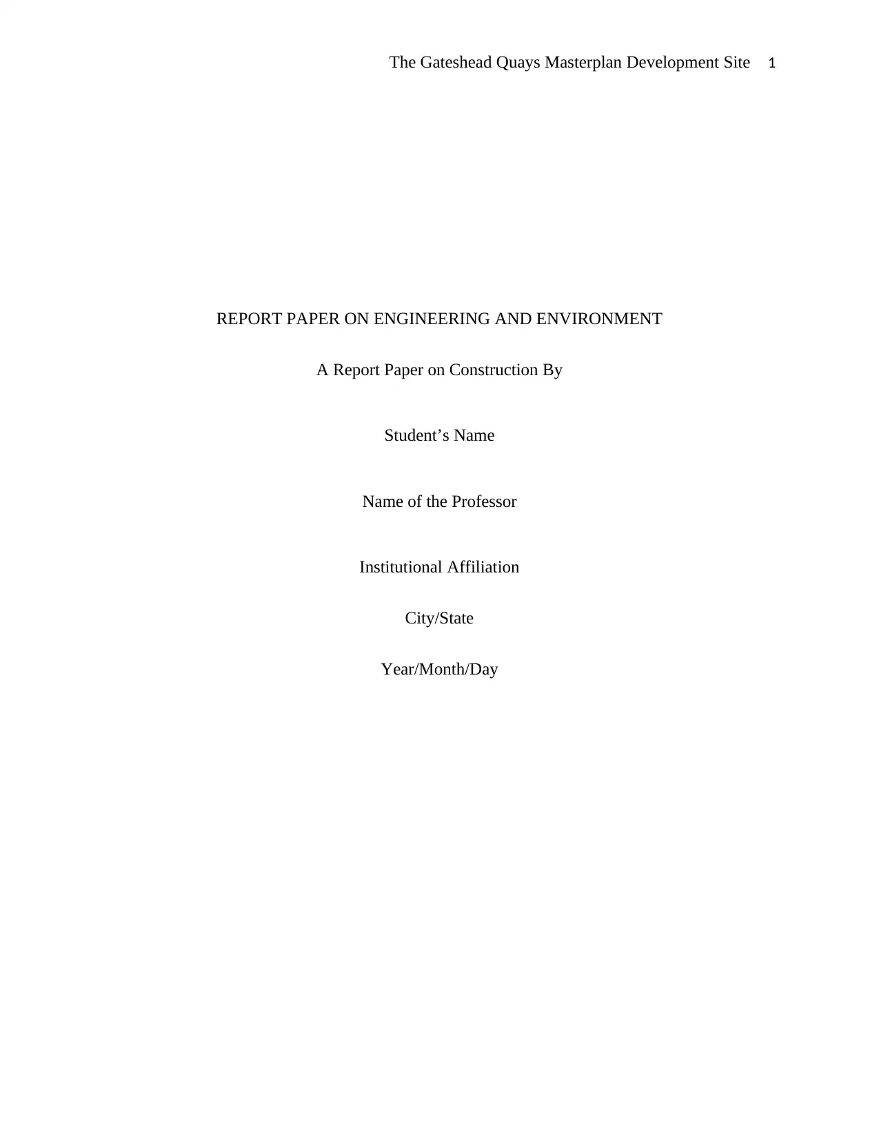
The assessment of the site seeks to investigate the infrastructure and buildings around the
site which may affect the construction process and design process. This site is situated directly
adjacent to the Millennium Bridge and located in the region between BALTIC Centre and Sage
and adjacent to the Millennium Bridge. The Gateshead Quays masterplan site extends to
49.94acres from Bridge in the western section to Mill Road in the Eastern section as shown in
figure 3. The Gateshead Millennium Bridge is an opening bridge spanning meters across the
River Tyne at quay level joining leisure and commercial developments on both sides of the river
(Castells, 2014).
Figure 1: Gateshead Millennium Bridge
INTRODUCTION
This report involves the assessment of the likely and available requirement for numerous
techniques for the appropriate qualification and description of the current advanced forms of
construction. The assessment seeks to evaluate and appraise design solutions for multi-storey
constructions in terms of construction performance, technical, and technology requirements. The
construction targeted for this assessment is in the prime position on Gateshead Quays which is a
10-acre site identified by Gateshead and Newcastle councils in the Urban Core Plan and Core
Strategy.
Preliminary Investigation
The assessment of the site seeks to investigate the infrastructure and buildings around the
site which may affect the construction process and design process. This site is situated directly
adjacent to the Millennium Bridge and located in the region between BALTIC Centre and Sage
and adjacent to the Millennium Bridge. The Gateshead Quays masterplan site extends to
49.94acres from Bridge in the western section to Mill Road in the Eastern section as shown in
figure 3. The Gateshead Millennium Bridge is an opening bridge spanning meters across the
River Tyne at quay level joining leisure and commercial developments on both sides of the river
(Castells, 2014).
Figure 1: Gateshead Millennium Bridge
The Gateshead Quays Masterplan Development Site 3
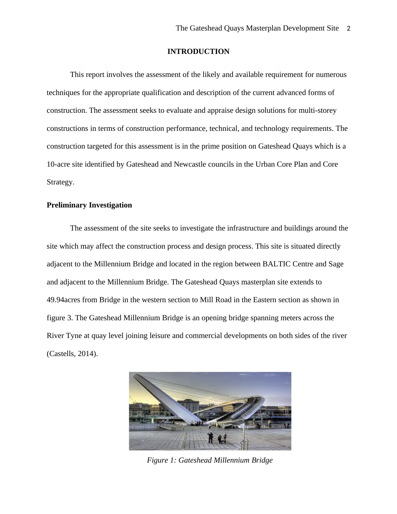
The construction process and design process of the buildings around the site has a
significant impact on the long-term sustainability of the project to be situated in the site
especially in the areas of thermal insulation standards, sound insulation standards, and space
provision. The constructions around the site will determine the design proposal since they will
directly affect the health and safety, productivity, and satisfaction with the design (Ofori, 2012).
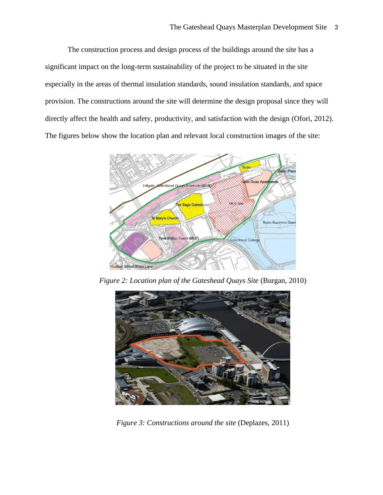
The figures below show the location plan and relevant local construction images of the site:
Figure 2: Location plan of the Gateshead Quays Site (Burgan, 2010)
Figure 3: Constructions around the site (Deplazes, 2011)
The construction process and design process of the buildings around the site has a
significant impact on the long-term sustainability of the project to be situated in the site
especially in the areas of thermal insulation standards, sound insulation standards, and space
provision. The constructions around the site will determine the design proposal since they will
directly affect the health and safety, productivity, and satisfaction with the design (Ofori, 2012).
The figures below show the location plan and relevant local construction images of the site:
Figure 2: Location plan of the Gateshead Quays Site (Burgan, 2010)
Figure 3: Constructions around the site (Deplazes, 2011)
⊘ This is a preview!⊘
Do you want full access?
Subscribe today to unlock all pages.
Trusted by 1+ million students worldwide
The Gateshead Quays Masterplan Development Site 4
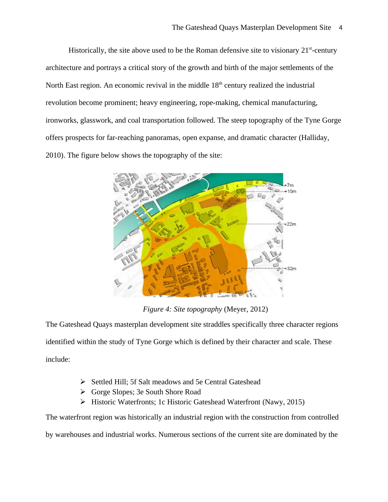
Historically, the site above used to be the Roman defensive site to visionary 21st-century
architecture and portrays a critical story of the growth and birth of the major settlements of the
North East region. An economic revival in the middle 18th century realized the industrial
revolution become prominent; heavy engineering, rope-making, chemical manufacturing,
ironworks, glasswork, and coal transportation followed. The steep topography of the Tyne Gorge
offers prospects for far-reaching panoramas, open expanse, and dramatic character (Halliday,
2010). The figure below shows the topography of the site:
Figure 4: Site topography (Meyer, 2012)
The Gateshead Quays masterplan development site straddles specifically three character regions
identified within the study of Tyne Gorge which is defined by their character and scale. These
include:
Settled Hill; 5f Salt meadows and 5e Central Gateshead
Gorge Slopes; 3e South Shore Road
Historic Waterfronts; 1c Historic Gateshead Waterfront (Nawy, 2015)
The waterfront region was historically an industrial region with the construction from controlled
by warehouses and industrial works. Numerous sections of the current site are dominated by the
Paraphrase This Document
Need a fresh take? Get an instant paraphrase of this document with our AI Paraphraser
The Gateshead Quays Masterplan Development Site 5
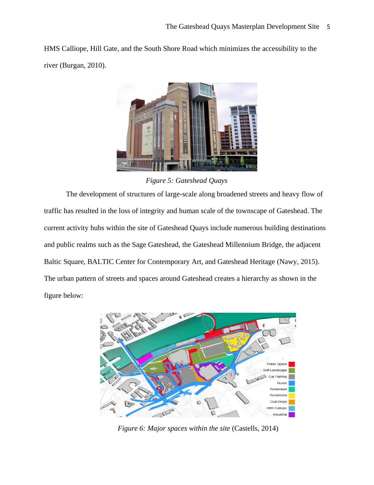
HMS Calliope, Hill Gate, and the South Shore Road which minimizes the accessibility to the
river (Burgan, 2010).
Figure 5: Gateshead Quays
The development of structures of large-scale along broadened streets and heavy flow of
traffic has resulted in the loss of integrity and human scale of the townscape of Gateshead. The
current activity hubs within the site of Gateshead Quays include numerous building destinations
and public realms such as the Sage Gateshead, the Gateshead Millennium Bridge, the adjacent
Baltic Square, BALTIC Center for Contemporary Art, and Gateshead Heritage (Nawy, 2015).
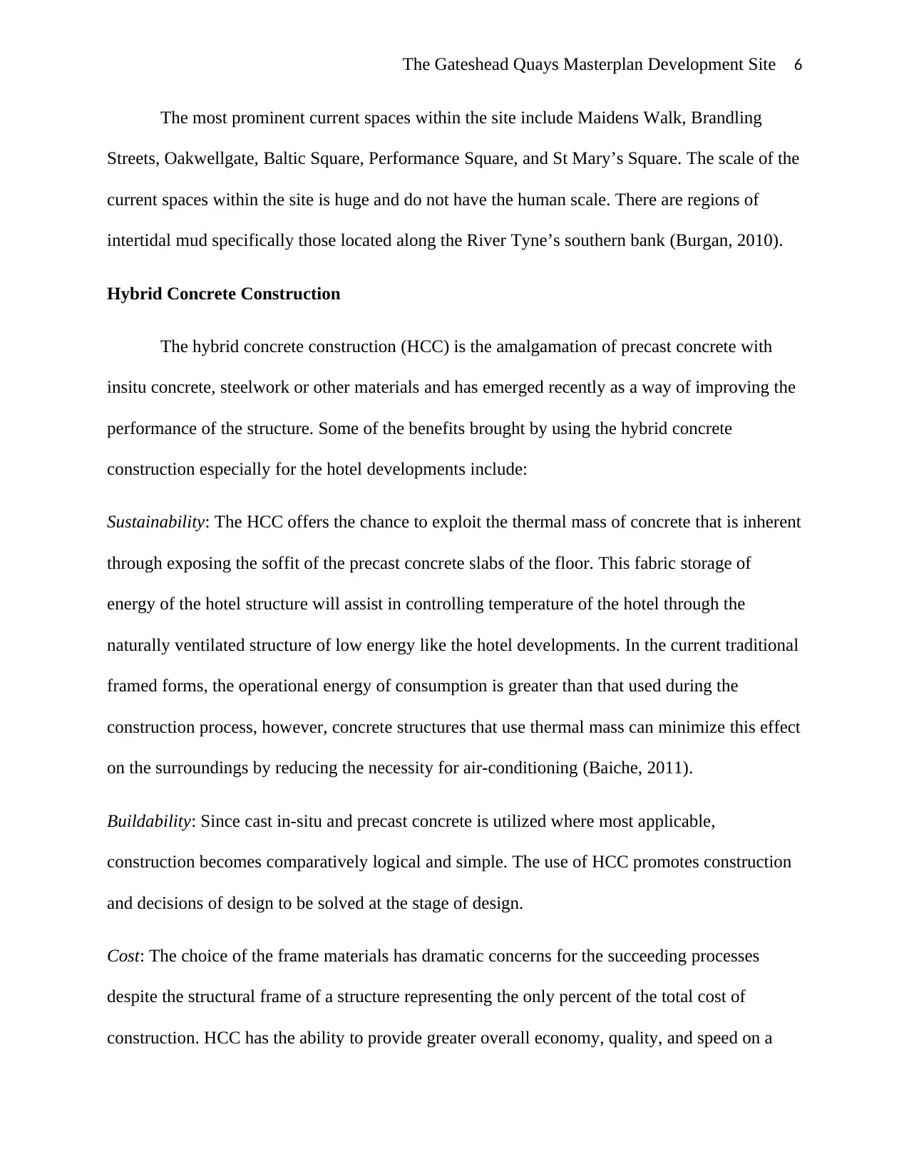
The urban pattern of streets and spaces around Gateshead creates a hierarchy as shown in the
figure below:
Figure 6: Major spaces within the site (Castells, 2014)
HMS Calliope, Hill Gate, and the South Shore Road which minimizes the accessibility to the
river (Burgan, 2010).
Figure 5: Gateshead Quays
The development of structures of large-scale along broadened streets and heavy flow of
traffic has resulted in the loss of integrity and human scale of the townscape of Gateshead. The
current activity hubs within the site of Gateshead Quays include numerous building destinations
and public realms such as the Sage Gateshead, the Gateshead Millennium Bridge, the adjacent
Baltic Square, BALTIC Center for Contemporary Art, and Gateshead Heritage (Nawy, 2015).
The urban pattern of streets and spaces around Gateshead creates a hierarchy as shown in the
figure below:
Figure 6: Major spaces within the site (Castells, 2014)
The Gateshead Quays Masterplan Development Site 6
The most prominent current spaces within the site include Maidens Walk, Brandling
Streets, Oakwellgate, Baltic Square, Performance Square, and St Mary’s Square. The scale of the
current spaces within the site is huge and do not have the human scale. There are regions of
intertidal mud specifically those located along the River Tyne’s southern bank (Burgan, 2010).
Hybrid Concrete Construction
The hybrid concrete construction (HCC) is the amalgamation of precast concrete with
insitu concrete, steelwork or other materials and has emerged recently as a way of improving the
performance of the structure. Some of the benefits brought by using the hybrid concrete
construction especially for the hotel developments include:
Sustainability: The HCC offers the chance to exploit the thermal mass of concrete that is inherent
through exposing the soffit of the precast concrete slabs of the floor. This fabric storage of
energy of the hotel structure will assist in controlling temperature of the hotel through the
naturally ventilated structure of low energy like the hotel developments. In the current traditional
framed forms, the operational energy of consumption is greater than that used during the
construction process, however, concrete structures that use thermal mass can minimize this effect
on the surroundings by reducing the necessity for air-conditioning (Baiche, 2011).
Buildability: Since cast in-situ and precast concrete is utilized where most applicable,
construction becomes comparatively logical and simple. The use of HCC promotes construction
and decisions of design to be solved at the stage of design.
Cost: The choice of the frame materials has dramatic concerns for the succeeding processes
despite the structural frame of a structure representing the only percent of the total cost of
construction. HCC has the ability to provide greater overall economy, quality, and speed on a
⊘ This is a preview!⊘
Do you want full access?
Subscribe today to unlock all pages.
Trusted by 1+ million students worldwide
The Gateshead Quays Masterplan Development Site 7
project. The utilization of concrete has extra benefits in assessing whole-life cost which is an
important factor to the PFI operators and owner-occupiers (Mert, 2010).
Suitable Hybrid Option
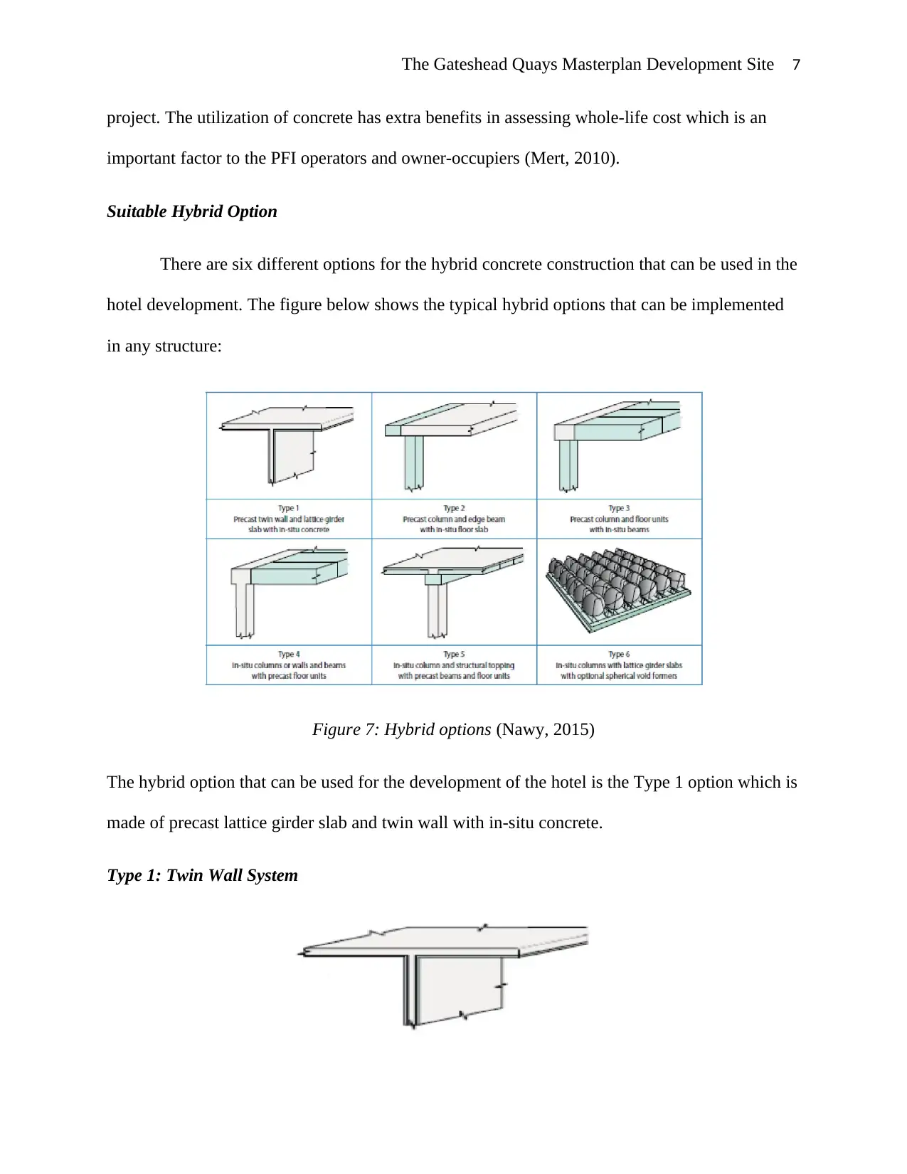
There are six different options for the hybrid concrete construction that can be used in the
hotel development. The figure below shows the typical hybrid options that can be implemented
in any structure:
Figure 7: Hybrid options (Nawy, 2015)
The hybrid option that can be used for the development of the hotel is the Type 1 option which is
made of precast lattice girder slab and twin wall with in-situ concrete.
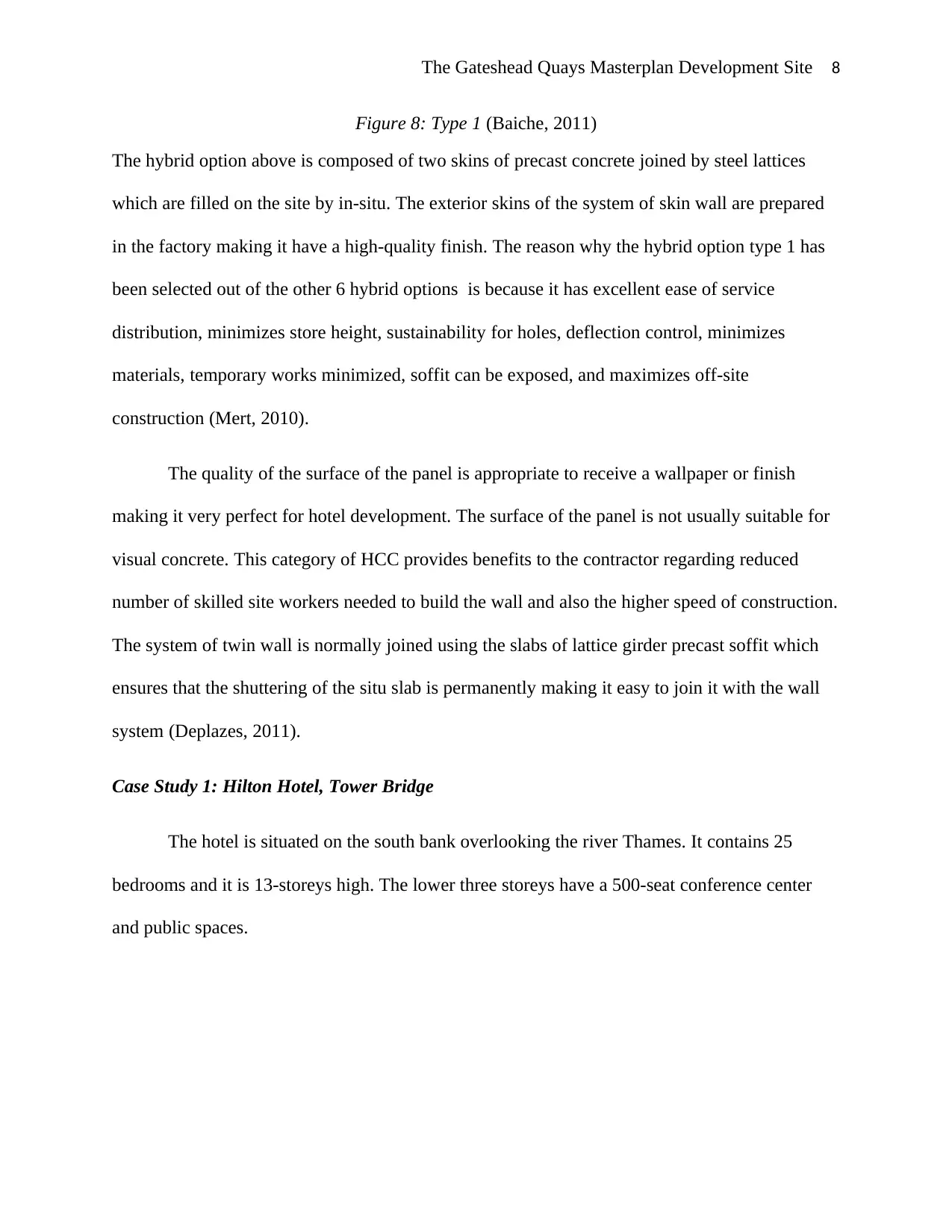
Type 1: Twin Wall System
project. The utilization of concrete has extra benefits in assessing whole-life cost which is an
important factor to the PFI operators and owner-occupiers (Mert, 2010).
Suitable Hybrid Option
There are six different options for the hybrid concrete construction that can be used in the
hotel development. The figure below shows the typical hybrid options that can be implemented
in any structure:
Figure 7: Hybrid options (Nawy, 2015)
The hybrid option that can be used for the development of the hotel is the Type 1 option which is
made of precast lattice girder slab and twin wall with in-situ concrete.
Type 1: Twin Wall System
Paraphrase This Document
Need a fresh take? Get an instant paraphrase of this document with our AI Paraphraser
The Gateshead Quays Masterplan Development Site 8
Figure 8: Type 1 (Baiche, 2011)
The hybrid option above is composed of two skins of precast concrete joined by steel lattices
which are filled on the site by in-situ. The exterior skins of the system of skin wall are prepared
in the factory making it have a high-quality finish. The reason why the hybrid option type 1 has
been selected out of the other 6 hybrid options is because it has excellent ease of service
distribution, minimizes store height, sustainability for holes, deflection control, minimizes
materials, temporary works minimized, soffit can be exposed, and maximizes off-site
construction (Mert, 2010).
The quality of the surface of the panel is appropriate to receive a wallpaper or finish
making it very perfect for hotel development. The surface of the panel is not usually suitable for
visual concrete. This category of HCC provides benefits to the contractor regarding reduced
number of skilled site workers needed to build the wall and also the higher speed of construction.
The system of twin wall is normally joined using the slabs of lattice girder precast soffit which
ensures that the shuttering of the situ slab is permanently making it easy to join it with the wall
system (Deplazes, 2011).
Case Study 1: Hilton Hotel, Tower Bridge
The hotel is situated on the south bank overlooking the river Thames. It contains 25
bedrooms and it is 13-storeys high. The lower three storeys have a 500-seat conference center
and public spaces.
The Gateshead Quays Masterplan Development Site 9
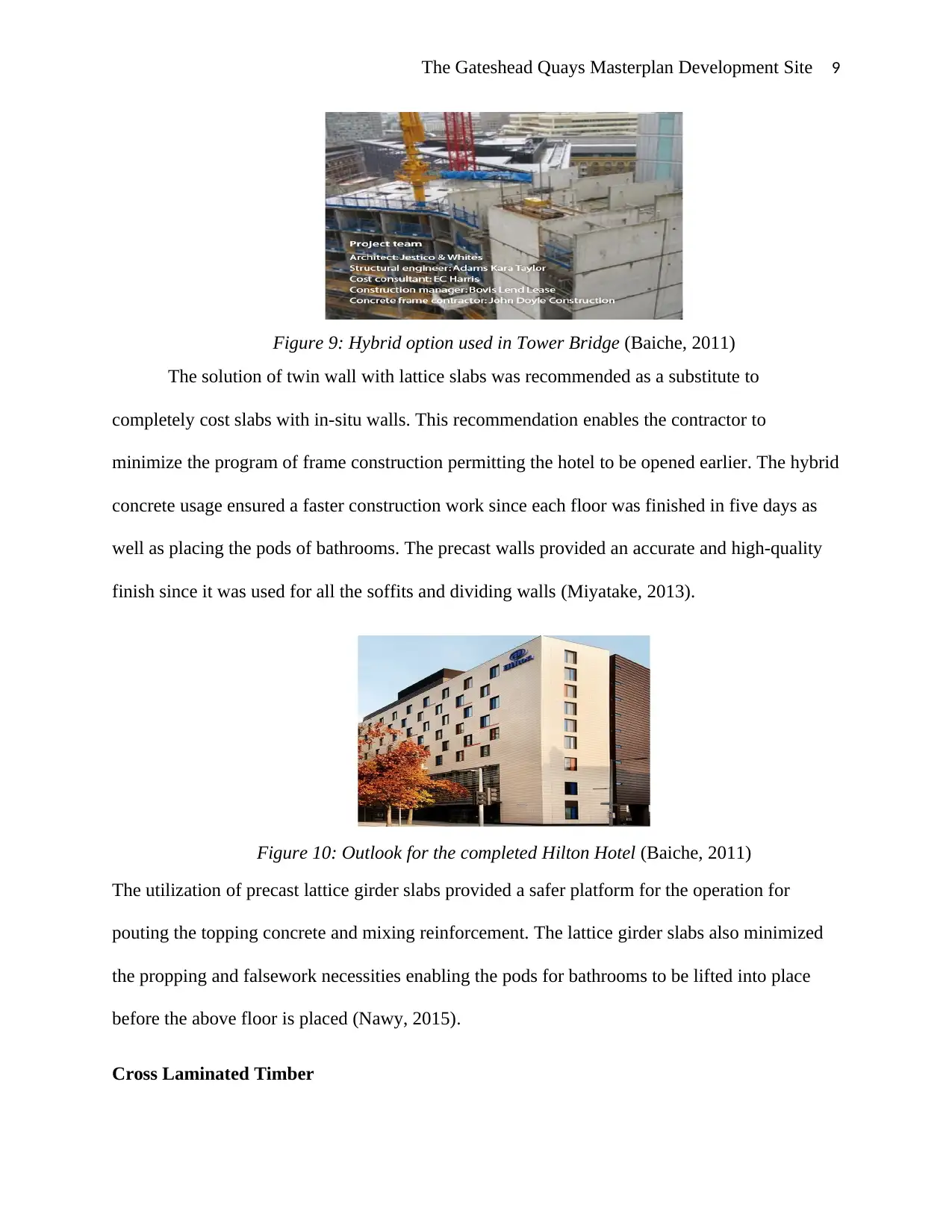
Figure 9: Hybrid option used in Tower Bridge (Baiche, 2011)
The solution of twin wall with lattice slabs was recommended as a substitute to
completely cost slabs with in-situ walls. This recommendation enables the contractor to
minimize the program of frame construction permitting the hotel to be opened earlier. The hybrid
concrete usage ensured a faster construction work since each floor was finished in five days as
well as placing the pods of bathrooms. The precast walls provided an accurate and high-quality
finish since it was used for all the soffits and dividing walls (Miyatake, 2013).
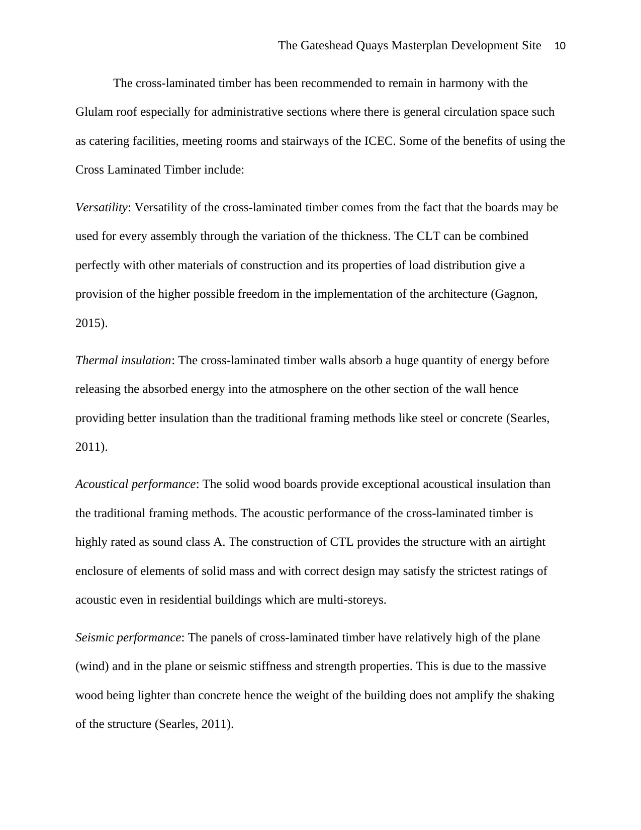
Figure 10: Outlook for the completed Hilton Hotel (Baiche, 2011)
The utilization of precast lattice girder slabs provided a safer platform for the operation for
pouting the topping concrete and mixing reinforcement. The lattice girder slabs also minimized
the propping and falsework necessities enabling the pods for bathrooms to be lifted into place
before the above floor is placed (Nawy, 2015).
Cross Laminated Timber
Figure 9: Hybrid option used in Tower Bridge (Baiche, 2011)
The solution of twin wall with lattice slabs was recommended as a substitute to
completely cost slabs with in-situ walls. This recommendation enables the contractor to
minimize the program of frame construction permitting the hotel to be opened earlier. The hybrid
concrete usage ensured a faster construction work since each floor was finished in five days as
well as placing the pods of bathrooms. The precast walls provided an accurate and high-quality
finish since it was used for all the soffits and dividing walls (Miyatake, 2013).
Figure 10: Outlook for the completed Hilton Hotel (Baiche, 2011)
The utilization of precast lattice girder slabs provided a safer platform for the operation for
pouting the topping concrete and mixing reinforcement. The lattice girder slabs also minimized
the propping and falsework necessities enabling the pods for bathrooms to be lifted into place
before the above floor is placed (Nawy, 2015).
Cross Laminated Timber
⊘ This is a preview!⊘
Do you want full access?
Subscribe today to unlock all pages.
Trusted by 1+ million students worldwide
The Gateshead Quays Masterplan Development Site 10
The cross-laminated timber has been recommended to remain in harmony with the
Glulam roof especially for administrative sections where there is general circulation space such
as catering facilities, meeting rooms and stairways of the ICEC. Some of the benefits of using the
Cross Laminated Timber include:
Versatility: Versatility of the cross-laminated timber comes from the fact that the boards may be
used for every assembly through the variation of the thickness. The CLT can be combined
perfectly with other materials of construction and its properties of load distribution give a
provision of the higher possible freedom in the implementation of the architecture (Gagnon,
2015).
Thermal insulation: The cross-laminated timber walls absorb a huge quantity of energy before
releasing the absorbed energy into the atmosphere on the other section of the wall hence
providing better insulation than the traditional framing methods like steel or concrete (Searles,
2011).
Acoustical performance: The solid wood boards provide exceptional acoustical insulation than
the traditional framing methods. The acoustic performance of the cross-laminated timber is
highly rated as sound class A. The construction of CTL provides the structure with an airtight
enclosure of elements of solid mass and with correct design may satisfy the strictest ratings of
acoustic even in residential buildings which are multi-storeys.
Seismic performance: The panels of cross-laminated timber have relatively high of the plane
(wind) and in the plane or seismic stiffness and strength properties. This is due to the massive
wood being lighter than concrete hence the weight of the building does not amplify the shaking
of the structure (Searles, 2011).
Paraphrase This Document
Need a fresh take? Get an instant paraphrase of this document with our AI Paraphraser
The Gateshead Quays Masterplan Development Site 11
Suitability of CLT
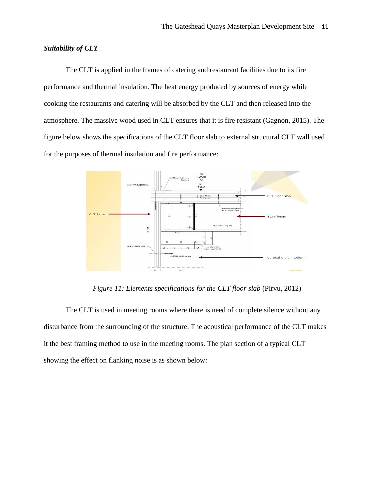
The CLT is applied in the frames of catering and restaurant facilities due to its fire
performance and thermal insulation. The heat energy produced by sources of energy while
cooking the restaurants and catering will be absorbed by the CLT and then released into the
atmosphere. The massive wood used in CLT ensures that it is fire resistant (Gagnon, 2015). The
figure below shows the specifications of the CLT floor slab to external structural CLT wall used
for the purposes of thermal insulation and fire performance:
Figure 11: Elements specifications for the CLT floor slab (Pirvu, 2012)
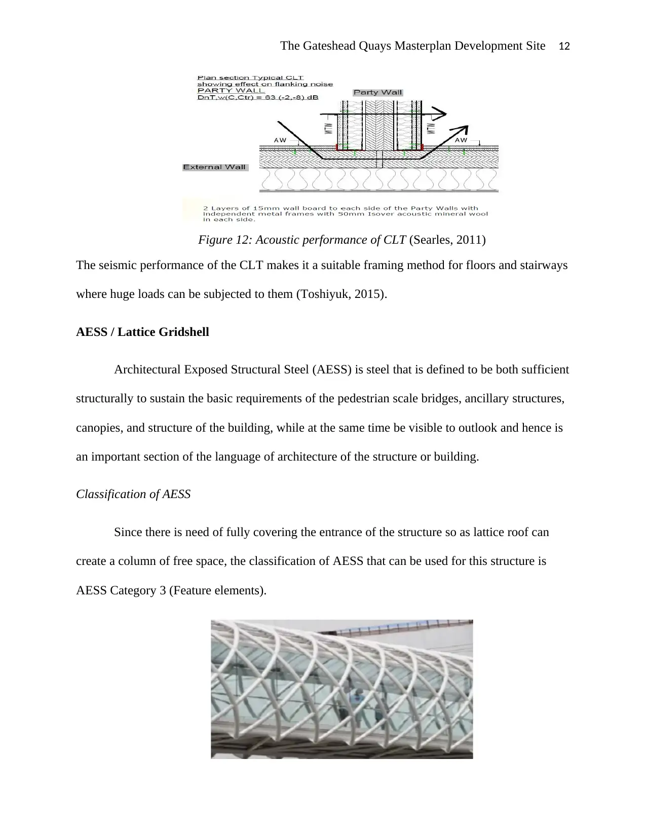
The CLT is used in meeting rooms where there is need of complete silence without any
disturbance from the surrounding of the structure. The acoustical performance of the CLT makes
it the best framing method to use in the meeting rooms. The plan section of a typical CLT
showing the effect on flanking noise is as shown below:
Suitability of CLT
The CLT is applied in the frames of catering and restaurant facilities due to its fire
performance and thermal insulation. The heat energy produced by sources of energy while
cooking the restaurants and catering will be absorbed by the CLT and then released into the
atmosphere. The massive wood used in CLT ensures that it is fire resistant (Gagnon, 2015). The
figure below shows the specifications of the CLT floor slab to external structural CLT wall used
for the purposes of thermal insulation and fire performance:
Figure 11: Elements specifications for the CLT floor slab (Pirvu, 2012)
The CLT is used in meeting rooms where there is need of complete silence without any
disturbance from the surrounding of the structure. The acoustical performance of the CLT makes
it the best framing method to use in the meeting rooms. The plan section of a typical CLT
showing the effect on flanking noise is as shown below:
The Gateshead Quays Masterplan Development Site 12
Figure 12: Acoustic performance of CLT (Searles, 2011)
The seismic performance of the CLT makes it a suitable framing method for floors and stairways
where huge loads can be subjected to them (Toshiyuk, 2015).
AESS / Lattice Gridshell
Architectural Exposed Structural Steel (AESS) is steel that is defined to be both sufficient
structurally to sustain the basic requirements of the pedestrian scale bridges, ancillary structures,
canopies, and structure of the building, while at the same time be visible to outlook and hence is
an important section of the language of architecture of the structure or building.
Classification of AESS
Since there is need of fully covering the entrance of the structure so as lattice roof can
create a column of free space, the classification of AESS that can be used for this structure is
AESS Category 3 (Feature elements).
⊘ This is a preview!⊘
Do you want full access?
Subscribe today to unlock all pages.
Trusted by 1+ million students worldwide
1 out of 21
Your All-in-One AI-Powered Toolkit for Academic Success.
+13062052269
info@desklib.com
Available 24*7 on WhatsApp / Email
![[object Object]](/_next/static/media/star-bottom.7253800d.svg)
Unlock your academic potential
Copyright © 2020–2026 A2Z Services. All Rights Reserved. Developed and managed by ZUCOL.