MSP5003 Auto and Component Design: Gearbox Specification Report
VerifiedAdded on 2021/04/21
|24
|5571
|134
Report
AI Summary
This report details the design and specification of a gearbox, focusing on the transfer of power from the engine to the wheels. It covers the design process, including calculations for gear ratios, material selection, and cost estimation. The report discusses different gearbox types, such as sliding mesh and constant mesh, and highlights the importance of gear ratio optimization for vehicle performance, fuel consumption, and environmental impact. Calculations for gear ratios, torque, and bending stress are provided, along with considerations for safety and environmental impact. The design process involves PDS (Product Design Specification) and the use of CAD software for 3D modeling and analysis using SolidWorks. The report also includes discussions on manufacturability and the selection of materials. This report is a comprehensive exploration of gearbox design principles and practical applications.
AUTO AND COMPONENT DESIGN MSP5003 UNIVERSITY OF BOLTON
MSP5003 - Auto and Component Design
TITLE: Report on Gearbox Specification and 3D modelling
AUTHOR: VIJAY KADIR RJ (1607306)
LECTURER: ROBERT HIGHAM
1 | P a g e V I J A Y K A D I R
MSP5003 - Auto and Component Design
TITLE: Report on Gearbox Specification and 3D modelling
AUTHOR: VIJAY KADIR RJ (1607306)
LECTURER: ROBERT HIGHAM
1 | P a g e V I J A Y K A D I R
Paraphrase This Document
Need a fresh take? Get an instant paraphrase of this document with our AI Paraphraser
AUTO AND COMPONENT DESIGN MSP5003 UNIVERSITY OF BOLTON
Table of Contents
ABSTRACT..............................................................................................................................................3
INTRODUCTION.....................................................................................................................................5
DESIGNING GEARBOX PROCESS.............................................................................................................6
CALCULATION:.......................................................................................................................................7
MATERIALS..........................................................................................................................................12
COST ESTIMATION...............................................................................................................................14
MANUFACTURABILITY.........................................................................................................................15
METHODOLOGY...................................................................................................................................17
CONCLUSION:......................................................................................................................................18
RECOMMENDATIONS..........................................................................................................................19
References...........................................................................................................................................20
APPENDIX:...........................................................................................................................................22
2 | P a g e V I J A Y K A D I R
AUTO AND COMPONENT DESIGN MSP5003 UNIVERSITY OF BOLTON
ABSTRACT: Designing a gearbox is done by taking and assembling
the many gears in required ratios of speed to come up with the end
speed that is to be produced. A gearbox posses many types of gears
that are combined in proper synchrony that allow reduction of
speed. Some of the gearbox types include; synchronic mesh gearbox,
sliding mesh gearbox and constant mesh gearbox. Taking note of the
sliding mesh gearbox, we are provided with two types, stationery
gears and sliding gears. Most applications of a sliding gear are
mounting it on to shafts that are splined making them function as
they slide along a shaft of an axis that allows different pair meshing
of the gears. These gearboxes alternatively can be made better in
using many ways since the system of transmission is manual and has
a number of disadvantages. Such improvements are possible by use
of different methods or its improvement done by improving the
selection of gear stepping and their ratios. Such factors that affect
these improvements are; fuel consumption, vehicle performance and
pollution rate. All these factors are improved by gear ratio varying in
the transmission system. Hence, the transmission system has to be
designed having ratio gears that are optimal allowing optimum
vehicle performance as well as reduced consumption of fuel making
the technology more friendly to the environment. If there is need to
improve the gearbox’s performance, there is required care in
selecting ratios of intermediate gears. The design of the project was
finally patched in using an analysis of solid works that analysed many
factors that were known to be essential.
3 | P a g e V I J A Y K A D I R
⊘ This is a preview!⊘
Do you want full access?
Subscribe today to unlock all pages.
Trusted by 1+ million students worldwide
AUTO AND COMPONENT DESIGN MSP5003 UNIVERSITY OF BOLTON
INTRODUCTION:
The major reasoning for having a gearbox in vehicles it to facilitate
the transfer of power that comes from engines to be directed to the
wheels via the driveshaft. Using various gears allows equally various
torque levels that are to be directed to the vehicle wheels with a
dependence to the speed that the vehicle moves changing the level
of torque requires the gears being used to be shifted by automatic or
manual means, this depends on the transmission type under study
(Salah & Aliofkhazraei, 2015).
The manual model that was produced first came from Louis-Rene in
unison with Emile Levassor. Their invention involved a transmission
system that allowed transmission of three speeds in 1894. They
produced the design that is the major point of starting for numerous
manual transmission system. Levassor and Panhard made use of
chain drives in the first transmission system. However, in the year
that came afterwards, 1898 Louis Renault used the first design that
was present and improved it to another level using the substitution
of the driveshaft to make use of a drive chain with an addition of
various axle that was applied in the rear wheels ton increase
transmission in the designed manual system. This design was key as
when the 20 the century began, most manufacturers of cars had to
use the non-synchronized transmission that was manual that
required improvement taking note of the past designed
Levassor/Panhard/Renault designs. The invention that followed was
the year 1928. Cadillac made use and developed a better-
synchronized transmission system that was manual, with the added
reduction in gear grinding and easier shifting of gears (Anon., 2016).
The improvement also had smooth gear shifting. There is a studied
basic gear system evolution concerning the manual gearbox. The use
of helical gears is the preference that is chosen first for designing this
gearbox due to the quiet and smooth operation of the gearbox in its
maximum speed level. However, these types of gears are difficult to
4 | P a g e V I J A Y K A D I R
Paraphrase This Document
Need a fresh take? Get an instant paraphrase of this document with our AI Paraphraser
AUTO AND COMPONENT DESIGN MSP5003 UNIVERSITY OF BOLTON
manufacture due to the increased difficulty and complexity in the
time, shape, and cost of the involved individual parts (Parker, 2008)
DESIGNING GEARBOX PROCESS
Specifications of product’s design: the production or manufacture of
these gearbox products involve the development of steps or the first
development of an imagination to the engineers to be involved.
These engineers would then turn the concept of these imaginations
into engineering files and drawings that depict the plan of
manufacturing the design. Use of PDS, therefore, would allow
elimination of unnecessary delay and checklist. The communication
inability to pass on an idea would make the eventual design look
similar to previous designs as well as the review cycle to make the
approval for the incoming step. Using the PDS procedure can be
developed only if the gaolsof the design are stated clearly. In PDS,
the goals involved have relations to one another, therefore, there is
used for rating. Another essential step is the writing of engineering
specifications (Genta & Morello, 2016).
One appropriate way that the goal of the design can be achieved is
by coming up with numerous design attributes. These attributes are
then rated depending on the engineering goals with specifications
guiding both designers and engineers. The end product could
produce different results due to the varying inputs in design. The
main purpose is to make the team of designers understand the goals
of the design in the imagined process. One way of achieving this is by
noting down specifications required by engineers with the help of
engineering design tools such as CAD software. This software allows
commencing with the initial process of production. Physical concepts
can easily be used by engineers in coming up with hand sketches.
The final 3D diagram could henceforth be developed by 3D CAD
5 | P a g e V I J A Y K A D I R
AUTO AND COMPONENT DESIGN MSP5003 UNIVERSITY OF BOLTON
software that optimizes specific model parts. Better knowledge of
the materials required for major purposes and the process of
manufacturing that satisfies the design of required gearbox design is
also facilitated by the software. Selection of material, as well as the
process of manufacturing, have to sync with the requirements of the
design. Use of PDS design allows various volumes of production. The
needs of the customers are therefore identified early enough
allowing their independence in the implementation of the final
design (Gkikas, 2016).
CALCULATION:
GEAR RATIO: this ratio has it the definition as direct measurement ratio of
depicted speeds of rotation of any interlocking gears. Overall, in the start,
there are two gears that include the drive gear that directly obtains more force
of rotation output by the engine having the larger size than the driven gear.
The last gear has a higher turn speed and it opposite the direction of the first
gear. This brings out the formula;
Gear ratio=T2/T1
T1= total teeth number of the first gear.
T2= total teeth number of the second gear.
Determination of the basic ratio in gears involves the use of at least two
engaged gears that is the gear train. Most cases involve the first gear being the
drive gear that has an attachment to motor shaft while the second gear is the
driven gear that ah an attachment to the load shaft. In this project, the plan is
to design a gearbox of 5-speed specification meaning there is a possibility of
using many gears between the mentioned two types. These many gears would
facilitate power transmission. Ideal gears are the name of the intermediate
gears in between the two. Determining the gear ratio involves proper meshing
that facilitates proper constant construct as one gear turns the other (Bosch,
2013). A comparison of the teeth number is another method that simpler to
use in finding the gear ratio in any two gears that interlock. One more way of
achieving this is by manual counting of the teeth of gears interlocking, dividing
the teeth number of the driven gear by the teeth number of the drive gear,
6 | P a g e V I J A Y K A D I R
⊘ This is a preview!⊘
Do you want full access?
Subscribe today to unlock all pages.
Trusted by 1+ million students worldwide
AUTO AND COMPONENT DESIGN MSP5003 UNIVERSITY OF BOLTON
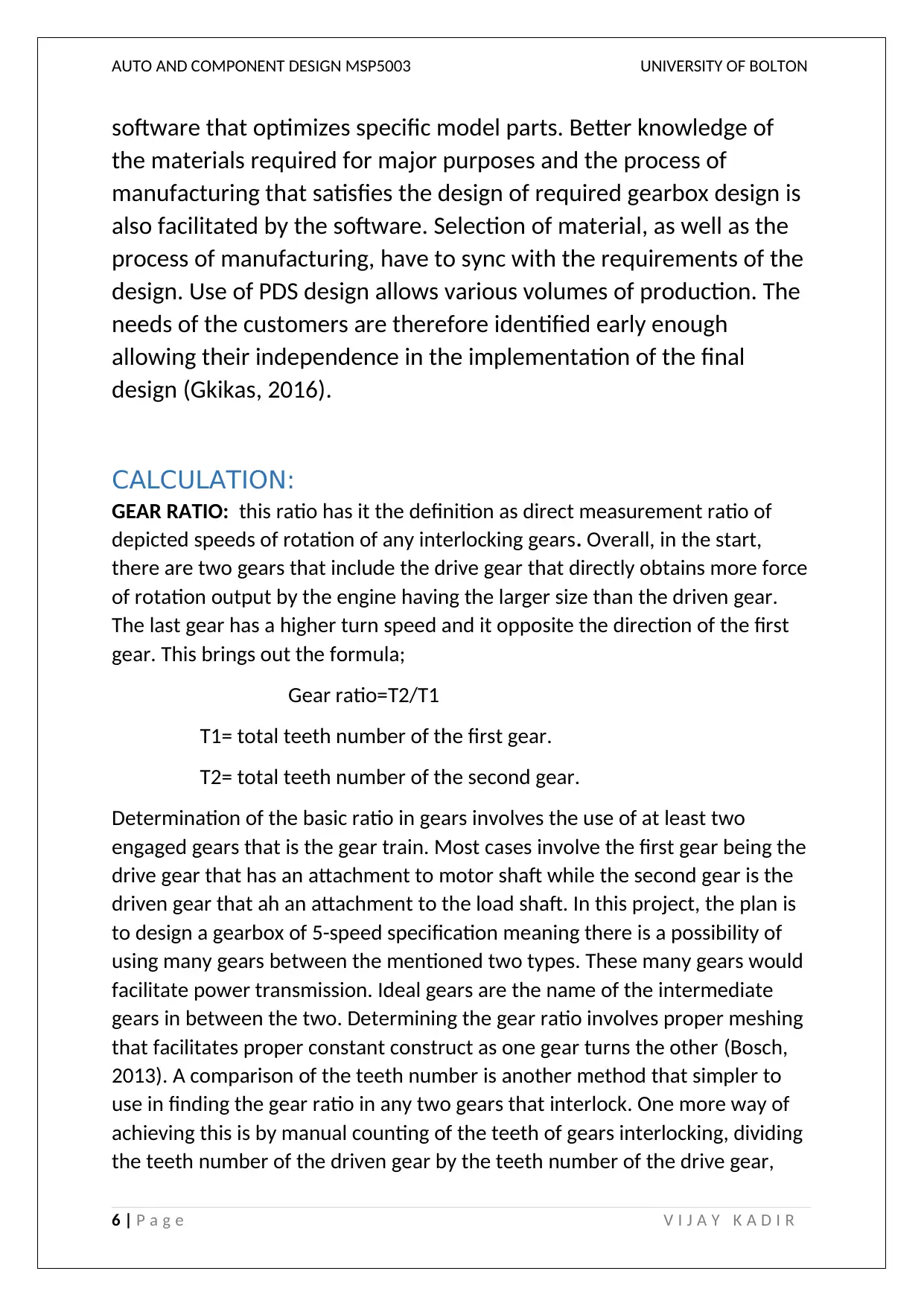
makes way for getting the gear ratio value. One important value of the ratio is
the ability of the drive gear to turn one and a half times so as to make the
driven gear turn once. This is because the driven gear has a bigger size than the
drive gear, therefore, it will run slower. Mass has a say in this movement. The
speed of the driven gear can easily be known based on the drive gear input
speed (Ramanujam & Tacke, 2016).
Ratio= ( Driven /Drive)* (Driven /Drive)
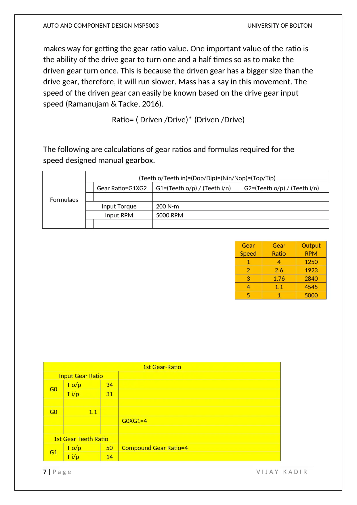
The following are calculations of gear ratios and formulas required for the
speed designed manual gearbox.
Formulaes
(Teeth o/Teeth in)=(Dop/Dip)=(Nin/Nop)=(Top/Tip)
Gear Ratio=G1XG2 G1=(Teeth o/p) / (Teeth i/n) G2=(Teeth o/p) / (Teeth i/n)
Input Torque 200 N-m
Input RPM 5000 RPM
1st Gear-Ratio
Input Gear Ratio
G0 T o/p 34
T i/p 31
G0 1.1
G0XG1=4
1st Gear Teeth Ratio
G1 T o/p 50 Compound Gear Ratio=4
T i/p 14
7 | P a g e V I J A Y K A D I R
Gear
Speed
Gear
Ratio
Output
RPM
1 4 1250
2 2.6 1923
3 1.76 2840
4 1.1 4545
5 1 5000
makes way for getting the gear ratio value. One important value of the ratio is
the ability of the drive gear to turn one and a half times so as to make the
driven gear turn once. This is because the driven gear has a bigger size than the
drive gear, therefore, it will run slower. Mass has a say in this movement. The
speed of the driven gear can easily be known based on the drive gear input
speed (Ramanujam & Tacke, 2016).
Ratio= ( Driven /Drive)* (Driven /Drive)
The following are calculations of gear ratios and formulas required for the
speed designed manual gearbox.
Formulaes
(Teeth o/Teeth in)=(Dop/Dip)=(Nin/Nop)=(Top/Tip)
Gear Ratio=G1XG2 G1=(Teeth o/p) / (Teeth i/n) G2=(Teeth o/p) / (Teeth i/n)
Input Torque 200 N-m
Input RPM 5000 RPM
1st Gear-Ratio
Input Gear Ratio
G0 T o/p 34
T i/p 31
G0 1.1
G0XG1=4
1st Gear Teeth Ratio
G1 T o/p 50 Compound Gear Ratio=4
T i/p 14
7 | P a g e V I J A Y K A D I R
Gear
Speed
Gear
Ratio
Output
RPM
1 4 1250
2 2.6 1923
3 1.76 2840
4 1.1 4545
5 1 5000
Paraphrase This Document
Need a fresh take? Get an instant paraphrase of this document with our AI Paraphraser
AUTO AND COMPONENT DESIGN MSP5003 UNIVERSITY OF BOLTON
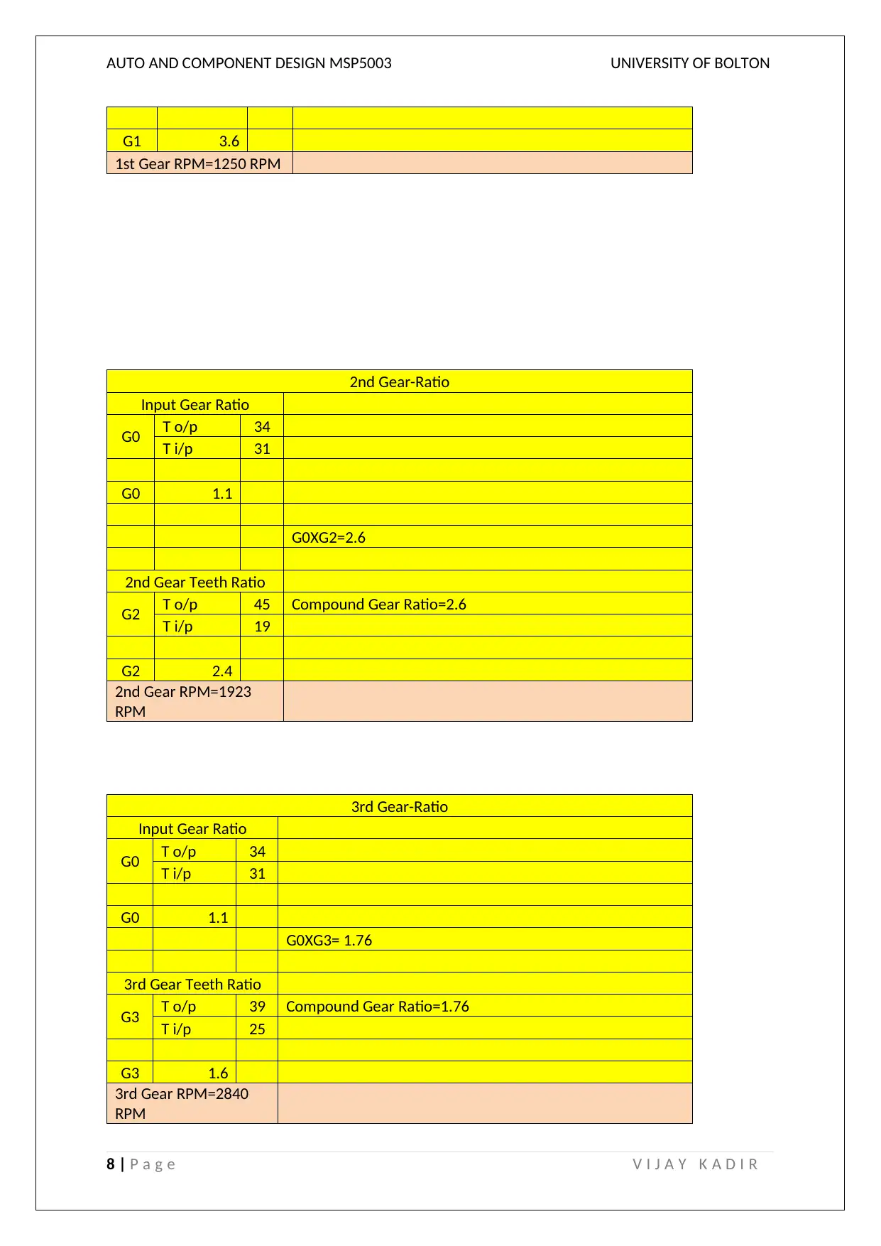
G1 3.6
1st Gear RPM=1250 RPM
2nd Gear-Ratio
Input Gear Ratio
G0 T o/p 34
T i/p 31
G0 1.1
G0XG2=2.6
2nd Gear Teeth Ratio
G2 T o/p 45 Compound Gear Ratio=2.6
T i/p 19
G2 2.4
2nd Gear RPM=1923
RPM
3rd Gear-Ratio
Input Gear Ratio
G0 T o/p 34
T i/p 31
G0 1.1
G0XG3= 1.76
3rd Gear Teeth Ratio
G3 T o/p 39 Compound Gear Ratio=1.76
T i/p 25
G3 1.6
3rd Gear RPM=2840
RPM
8 | P a g e V I J A Y K A D I R
AUTO AND COMPONENT DESIGN MSP5003 UNIVERSITY OF BOLTON
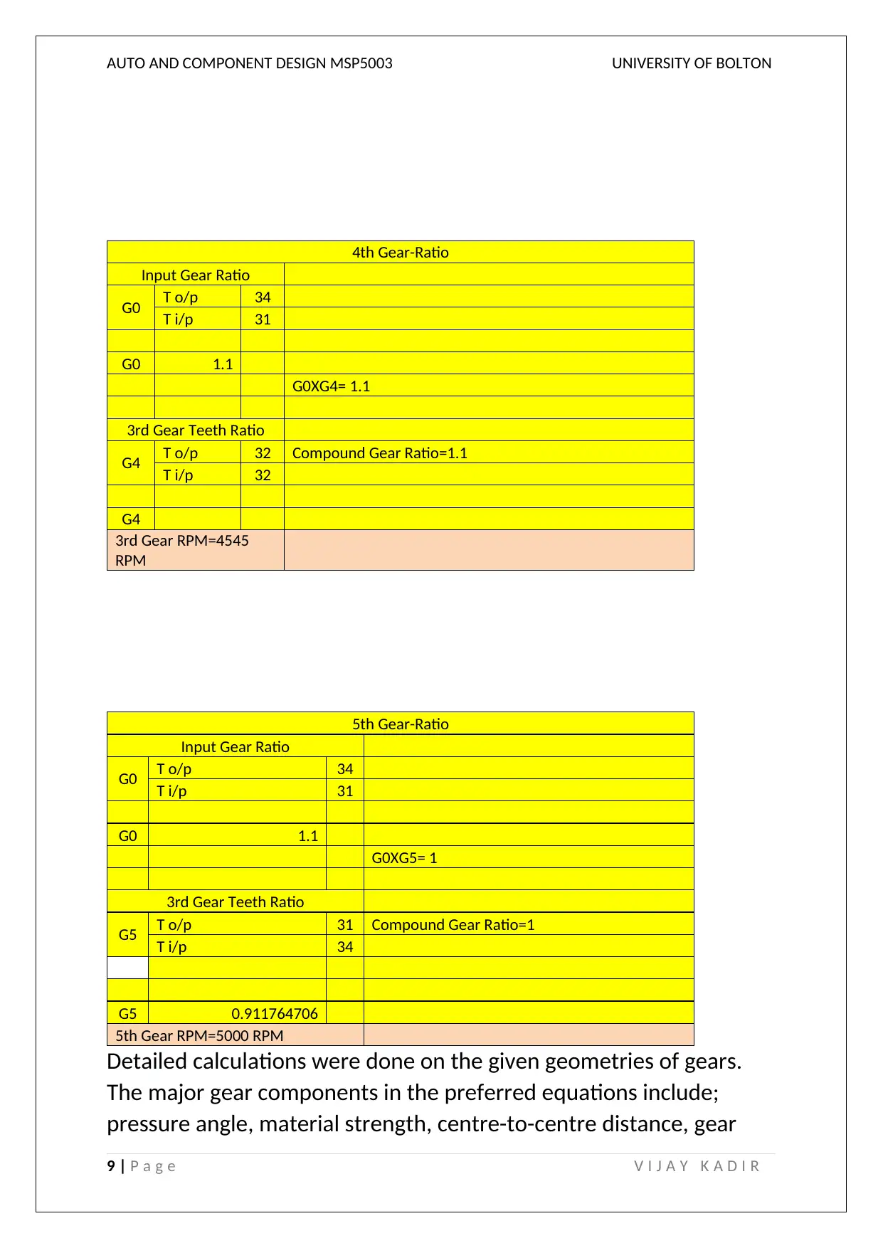
4th Gear-Ratio
Input Gear Ratio
G0 T o/p 34
T i/p 31
G0 1.1
G0XG4= 1.1
3rd Gear Teeth Ratio
G4 T o/p 32 Compound Gear Ratio=1.1
T i/p 32
G4
3rd Gear RPM=4545
RPM
5th Gear-Ratio
Input Gear Ratio
G0 T o/p 34
T i/p 31
G0 1.1
G0XG5= 1
3rd Gear Teeth Ratio
G5 T o/p 31 Compound Gear Ratio=1
T i/p 34
G5 0.911764706
5th Gear RPM=5000 RPM
Detailed calculations were done on the given geometries of gears.
The major gear components in the preferred equations include;
pressure angle, material strength, centre-to-centre distance, gear
9 | P a g e V I J A Y K A D I R
⊘ This is a preview!⊘
Do you want full access?
Subscribe today to unlock all pages.
Trusted by 1+ million students worldwide
AUTO AND COMPONENT DESIGN MSP5003 UNIVERSITY OF BOLTON
reduction ratio, gear teeth number and face width. Parameters need
to be loaded into gear design in study making this step very
important. The determination of these parameters involves coming
up with the pitch-line velocity as well as determining the bending
stress of every gear tooth. This has its importance in ensuring proper
material selection. Materials selected have to be strong enough
allowing support of stress that was calculated. Calculation of bending
stress is made possible by the use of Lewis factor, max tangential and
face width. Such parameters are used in calculating maximum stress.
Lewis factor was produced by the use of pressure angle on gears and
teeth number er gear. Talking about safety, has its numerous
relations to application factor, size factor, form factor, rim thickness,
load distribution and dynamic factor (Zurschmeide, 2016).
M = PITCH DIAMETER/NUMBER OF TEETH (Zurschmeide, 2016)
BENDING STRESS = K*W/M*B*Y (Zurschmeide, 2016)
Torque: transmitted force system is done using and via the machine
or structural member, with the capability of developing efficient
rotational displacement about the axis longitude.
Output Torque= Torque input/Gear Ratio (Zurschmeide, 2016).
In the above equation, the torque input equals torque output. The
torque input is put on an assumption.
ENVIRONMENT AND SAFETY: one the design was completed for all
of its components, an analysis of safety is to be performed. This
analysis makes sure the design is safe and secure with importance
focused on safety in assembling. Unfortunately, a well-assembled
design of gearbox has its safety risk that come from slight improper
10 | P a g e V I J A Y K A D I R
Paraphrase This Document
Need a fresh take? Get an instant paraphrase of this document with our AI Paraphraser
AUTO AND COMPONENT DESIGN MSP5003 UNIVERSITY OF BOLTON
synchronisation. The risk involved in this stage was improved to a
degree that had better clarity before activation of the performance
of the shaft. Any concerns about the environment are the addressed.
This possible to be analysed by critically investigating the material
used in making the used gears. Special care has to be taken when
selecting the materials of the gear. Alloys of aluminium were
considered to be detrimental to the environment if compared to cast
iron or steel. Effects to the environment usually come to view when
aluminium is being processed (Adler, 2007). Placement of products
for mass development makes this consideration be looked at larger
scales. Every country has its requirements in conserving the
environment. Choosing greater toxic materials would lead to equally
greater pollution of the environment. Such choices would mean
increased cost of running the vehicle gearbox design. Wholly, the
discussion of some material parts in mass production has its
importance in consideration of various options allowing better
designing of these gearboxes (Ebsch, 2010).
MATERIALS:
Design of gearboxes in this study has its focus on using numerous
options of materials. To begin with, the majorly looked at
components are the metals that have great endurance in
sustainability, durability and loading parameters. Since the is the use
of gears and shafts in this required project in having high resistance
to wear, the sued gears were of steel (Corpor, 2016). The shaft
selected material was an alloy due to the included bending loads.
Material that was selected had to be hardened with high tear and
wear resistance. Another feature is the use of an-susceptible
deformability in the action of performance torsion as well as various
bending cycles. In the section of gear hubs, the material that seemed
ideal was to be of lower density than steel so as o reduce the weight
of the gearbox in total. An alloy of aluminium seemed the chosen
11 | P a g e V I J A Y K A D I R
AUTO AND COMPONENT DESIGN MSP5003 UNIVERSITY OF BOLTON
option due to the future of enduring stress. Such an alloy would also
avail the needed elasticity modulus required in press-fit hubs. A
negative effect is a constant stress due to the spline interacting.
Aluminium has the benefit of better cost-effective than other
components possessing features. Taking note of numerous analysis,
an alloy of steel was produced to make the gears while the shift was
made of aluminium alloy. Hence, the manufacturing process involved
analysis of gears and shafts. The shaft calculations were therefore
begun (Smith, 2016). The conventional method of machining seemed
to be the better choice in shaft making. Torque to be transferred had
to be included for the conduction of an analysis of bending stresses.
The force and direction were determined on the analysed shaft. An
assumption was made that all of the forces that were involved had
horizontal alignment. The sheer force was calculated across the shaft
from left to right. Shear forces obtained as well as the distance every
force is located from static ends allowed calculation of bending
moments (Ebsch, 2010).
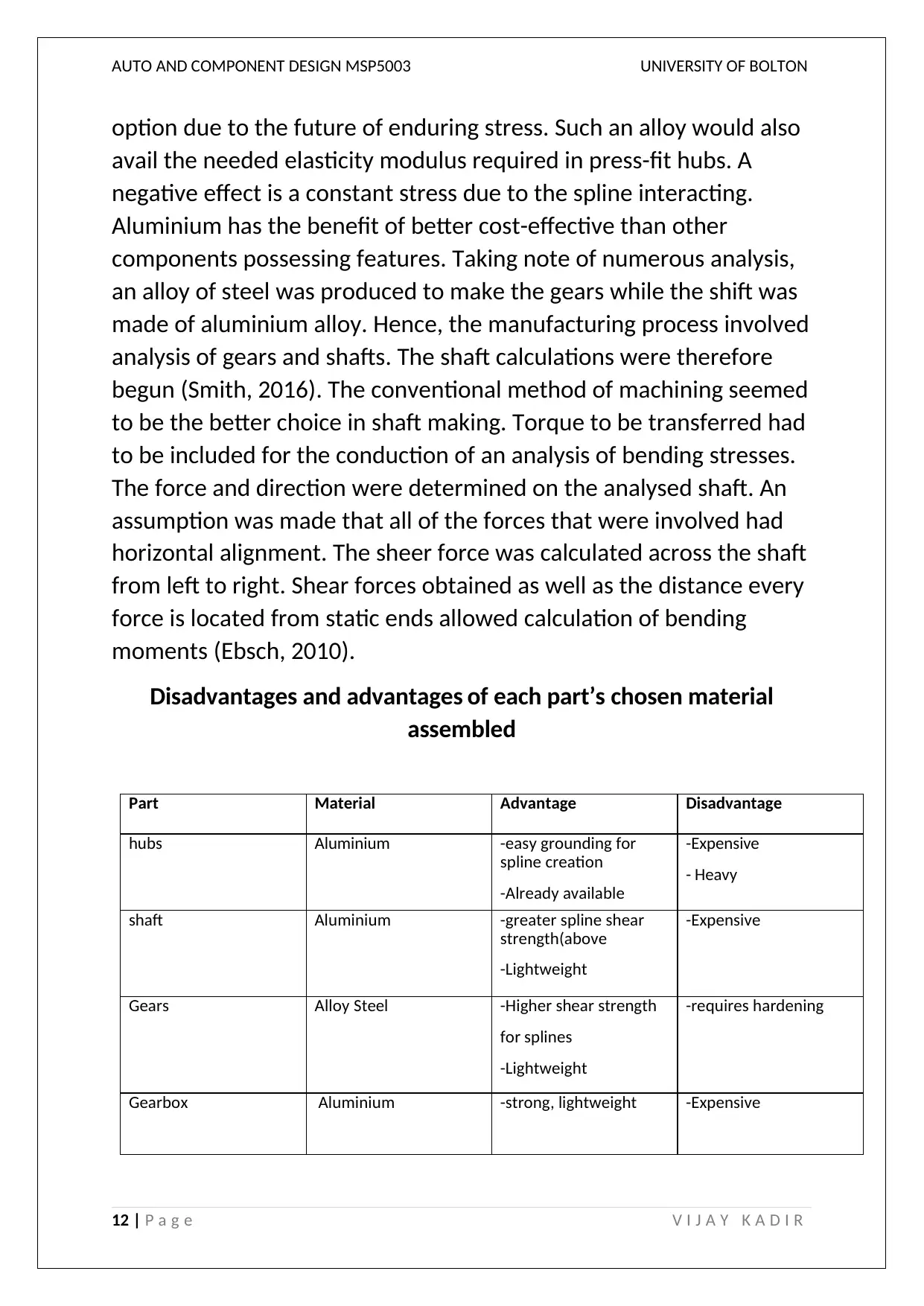
Disadvantages and advantages of each part’s chosen material
assembled
Part Material Advantage Disadvantage
hubs Aluminium -easy grounding for
spline creation
-Already available
-Expensive
- Heavy
shaft Aluminium -greater spline shear
strength(above
-Lightweight
-Expensive
Gears Alloy Steel -Higher shear strength
for splines
-Lightweight
-requires hardening
Gearbox Aluminium -strong, lightweight -Expensive
12 | P a g e V I J A Y K A D I R
option due to the future of enduring stress. Such an alloy would also
avail the needed elasticity modulus required in press-fit hubs. A
negative effect is a constant stress due to the spline interacting.
Aluminium has the benefit of better cost-effective than other
components possessing features. Taking note of numerous analysis,
an alloy of steel was produced to make the gears while the shift was
made of aluminium alloy. Hence, the manufacturing process involved
analysis of gears and shafts. The shaft calculations were therefore
begun (Smith, 2016). The conventional method of machining seemed
to be the better choice in shaft making. Torque to be transferred had
to be included for the conduction of an analysis of bending stresses.
The force and direction were determined on the analysed shaft. An
assumption was made that all of the forces that were involved had
horizontal alignment. The sheer force was calculated across the shaft
from left to right. Shear forces obtained as well as the distance every
force is located from static ends allowed calculation of bending
moments (Ebsch, 2010).
Disadvantages and advantages of each part’s chosen material
assembled
Part Material Advantage Disadvantage
hubs Aluminium -easy grounding for
spline creation
-Already available
-Expensive
- Heavy
shaft Aluminium -greater spline shear
strength(above
-Lightweight
-Expensive
Gears Alloy Steel -Higher shear strength
for splines
-Lightweight
-requires hardening
Gearbox Aluminium -strong, lightweight -Expensive
12 | P a g e V I J A Y K A D I R
⊘ This is a preview!⊘
Do you want full access?
Subscribe today to unlock all pages.
Trusted by 1+ million students worldwide
1 out of 24
Related Documents


Your All-in-One AI-Powered Toolkit for Academic Success.
+13062052269
info@desklib.com
Available 24*7 on WhatsApp / Email
![[object Object]](/_next/static/media/star-bottom.7253800d.svg)
Unlock your academic potential
Copyright © 2020–2026 A2Z Services. All Rights Reserved. Developed and managed by ZUCOL.