Geotechnical Engineering Assignment 1: Site Investigation and Design

Verified

Added on  2022/09/01

|20
|3006
|26
Homework Assignment
AI Summary
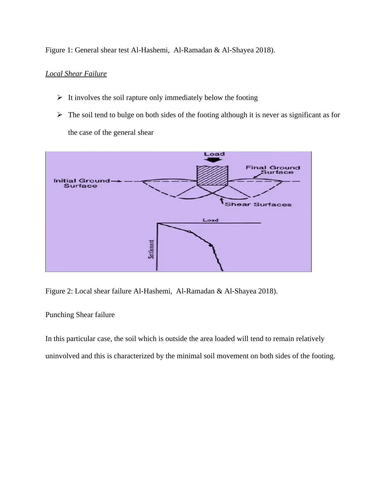
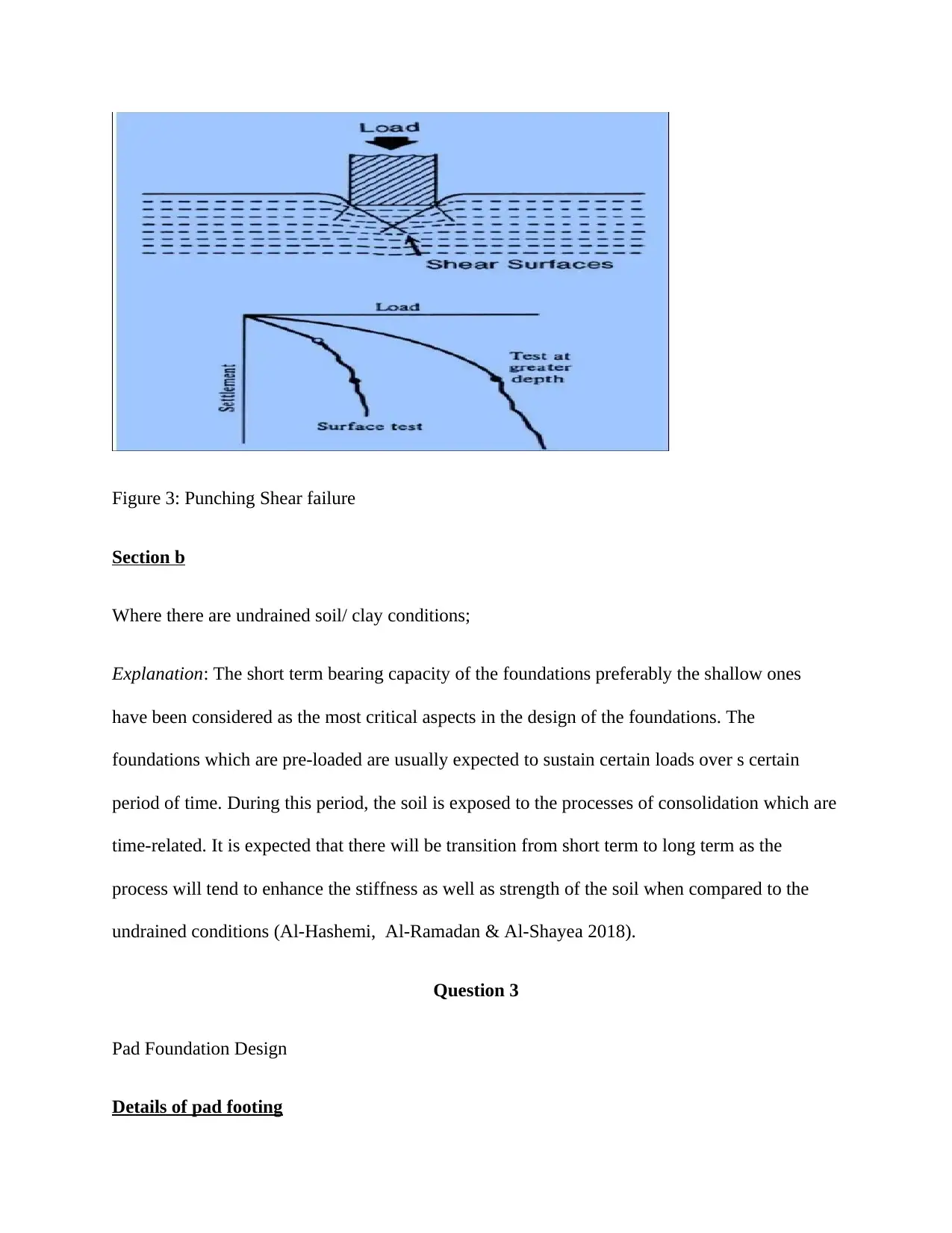
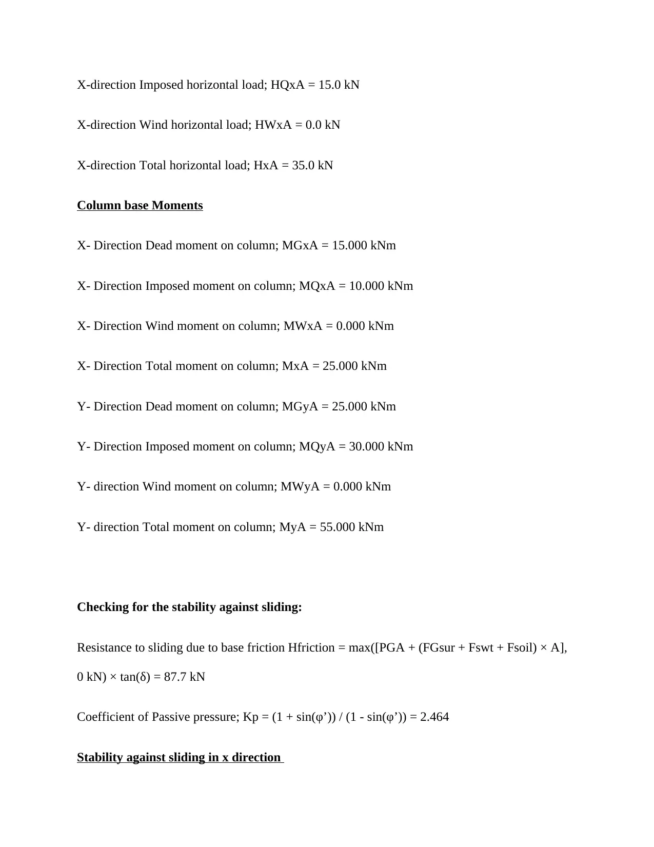
This document presents a comprehensive solution to a geotechnical engineering assignment, covering key aspects of the field. The assignment begins with a detailed site investigation, outlining the major steps involved, including desk studies, site reconnaissance, exploration, sampling, in-situ testing, laboratory testing, and report writing. It then delves into the Direct Shear Test, discussing its method, advantages, disadvantages, and practical applications in geotechnical design. The assignment also addresses bearing capacity failures, differentiating between general, local, and punching shear failures, and explaining the difference between short-term and long-term bearing capacity under undrained soil conditions. Furthermore, the solution includes a detailed pad foundation design, providing calculations for various parameters such as loads, moments, stability against sliding and overturning, base reactions, and base pressures. Finally, the assignment explores the Australian Standard AS2870 – 2011 for residential slabs and footings, discussing site classification, particularly Class "P" sites, and the environmental and geological factors that affect them. This document offers valuable insights into various facets of geotechnical engineering, providing a well-rounded understanding of the subject matter.
Document Page
GEOTECHNICAL ENGINEERING
[Author Name(s), First M. Last, Omit Titles and Degrees]
[Institutional Affiliation(s)]
tabler-icon-diamond-filled.svg

Secure Best Marks with AI Grader

Need help grading? Try our AI Grader for instant feedback on your assignments.
Document Page
Site Investigation
Question 1
Section a
Steps involved in the site investigations
Part I
1) Desk study
2) Site reconnaissance
3) Exploration and sampling of the site:
4) In situ/field tests
5) Laboratory Testing
6) Report writing
Part II
i. Desk study: It involves collection or gathering of information related to the site including
the maps, geological maps among others
ii. Site reconnaissance: It is usually desirable to have early examination of the site by the
qualified experts. These may include land surveyors, geologists, and soil engineers
among others. The collection of the information should be done entirely as per the layout
of the site.
iii. Exploration and sampling of the site: Detailed geology investigation as well as conditions
of the subsoil through the use of surveys of the surface, headings, trial pits, boreholes
among others
Document Page
iv. In situ/field tests: This includes the tests which is carried out on the site before or during
the process of the construction; ground tests like standard penetration, shear vane, cone
penetration, pressure metre, plate bearing etc (Ko et al.2019).
v. Laboratory Testing: This will include tests on the undisturbed and disturbed samples
which have been submitted by the team from the site; tests on the soils for quality,
classification, shear strength, permeability among others
vi. Report writing: It is the last stage of site investigation. It involves compilation of the
details of the study geologically including the results of boring, structures, stratigraphy
and mapping.
Section b
Part I
Geotechnical method commonly used:
Direct Shear Test
Part II
Advantages
The preparation of the sample is usually very easy
Drainage is very quickly since the sample’s thickness is very less
It is the best option for carrying out the drained tests for the cases of soils which are
cohesion less
The used apparatus are cheap relatively
Document Page
Disadvantages
The conditions of the stress will only be known at failure.
The distribution of stress on the planes of failure is never uniform
The shear area gradually reduces as the progresses are noted on the tests
There is fixed orientation of the plane of failure
It is very difficult to control the conditions of the drainage.
Part III
Potential use of test results in geotechnical engineering design
Apparatus
The activities of the tests are carried out on the specimen of the soil which has been placed in the
shear box. The shear box is split into at least two halves along the plane horizontally. The shear
box’s sizes is actually 60X60X50mm. The horizontal division of the box is done in such a way
that the plane of division passes through the centre. The two halves will be held together by the
use of locking pins or they will be perforated according to the conditions for testing
(Moghaddam et al.2018).
Testing Procedure
The specimen of soil of size 60 x 60 x 25 mm would be taken. This sample is placed directly into
the shear box directly before it is compacted. The porous stone, upper grid plate as well as
pressure pad is placed on the specimen. The shear loads and normal loads is then applied until
the point of failure.
The presentation of the results will then be done in the form of:
tabler-icon-diamond-filled.svg

Secure Best Marks with AI Grader

Need help grading? Try our AI Grader for instant feedback on your assignments.
Document Page
Stress – strain curve
Mohr’s circle
Failure envelope
Question 2
Section a
Types of bearing capacity failures:
General shear failure
Local shear failure
Punching shear failure
Characteristics
General shear failures
It involves underlying soil total rupture
The soil has continuous shear failure to the ground surface from below the footing
Document Page
Figure 1: General shear test Al-Hashemi, Al-Ramadan & Al-Shayea 2018).
Local Shear Failure
It involves the soil rapture only immediately below the footing
The soil tend to bulge on both sides of the footing although it is never as significant as for
the case of the general shear
Figure 2: Local shear failure Al-Hashemi, Al-Ramadan & Al-Shayea 2018).
Punching Shear failure
In this particular case, the soil which is outside the area loaded will tend to remain relatively
uninvolved and this is characterized by the minimal soil movement on both sides of the footing.
Document Page
Figure 3: Punching Shear failure
Section b
Where there are undrained soil/ clay conditions;
Explanation: The short term bearing capacity of the foundations preferably the shallow ones
have been considered as the most critical aspects in the design of the foundations. The
foundations which are pre-loaded are usually expected to sustain certain loads over s certain
period of time. During this period, the soil is exposed to the processes of consolidation which are
time-related. It is expected that there will be transition from short term to long term as the
process will tend to enhance the stiffness as well as strength of the soil when compared to the
undrained conditions (Al-Hashemi, Al-Ramadan & Al-Shayea 2018).
Question 3
Pad Foundation Design
Details of pad footing
tabler-icon-diamond-filled.svg

Paraphrase This Document

Need a fresh take? Get an instant paraphrase of this document with our AI Paraphraser
Document Page
Length, L = 2500 mm
Width, B = 2000 mm.
Area ; A = L × B = 5.0 m2
Depth ; h = 400 mm
Depth of soil ove footing of pad type; hsoil = 200 mm
Concrete density; ρconc = 23.6 kN/m3
Details of the columns
Base length of the column; lA = 300 mm
Base width of the column; bA = 300 mm
Eccentricity in the column x; ePxA = 0 mm
Eccentricity in the column y; ePyA = 0 mm
Soil Details
Mobilisation factor; m= ;1.5;
Soil density; ρsoil = 20.0 kN/m3
Shear strength of the design; φ’ = 25.0 deg
Base friction of the design; δ = 19.3 deg
Allowable bearing pressure; Pbearing = 200 kN/m2
Document Page
Column Axial loading
Column dead axial loading; PGA = 200.0 kN
Imposed axial load ; PQA = 165.0 kN
Axial load due to wind ; PWA = 0.0 kN
Total axial loads; PA = 365.0 kN
Foundation loads
Surcharge dead load; FGsur = 0.000 kN/m2
Surcharge dead load; FQsur = 0.000 kN/m2
Self- weight for pad footing; Fswt = h × ρconc = 9.440 kN/m2
Self weight for the soil; Fsoil = hsoil × ρsoil = 4.000 kN/m2
Total load of foundation; F = A × (FGsur + FQsur + Fswt + Fsoil) = 50.4 kN
Loading on Horizontal components on column base
Y-direction Dead horizontal load ; HGyA = 5.0 kN
Y-direction Imposed horizontal load ; HQyA = 5.0 kN
Y-direction Wind horizontal load; HWyA = 0.0 kN
Y-direction Total horizontal load ; HyA = 10.0 kN
X-direction Dead horizontal load; HGxA = 20.0 kN
Document Page
X-direction Imposed horizontal load; HQxA = 15.0 kN
X-direction Wind horizontal load; HWxA = 0.0 kN
X-direction Total horizontal load; HxA = 35.0 kN
Column base Moments
X- Direction Dead moment on column; MGxA = 15.000 kNm
X- Direction Imposed moment on column; MQxA = 10.000 kNm
X- Direction Wind moment on column; MWxA = 0.000 kNm
X- Direction Total moment on column; MxA = 25.000 kNm
Y- Direction Dead moment on column; MGyA = 25.000 kNm
Y- Direction Imposed moment on column; MQyA = 30.000 kNm
Y- direction Wind moment on column; MWyA = 0.000 kNm
Y- direction Total moment on column; MyA = 55.000 kNm
Checking for the stability against sliding:
Resistance to sliding due to base friction Hfriction = max([PGA + (FGsur + Fswt + Fsoil) × A],
0 kN) × tan(δ) = 87.7 kN
Coefficient of Passive pressure; Kp = (1 + sin(φ’)) / (1 - sin(φ’)) = 2.464
Stability against sliding in x direction
tabler-icon-diamond-filled.svg

Secure Best Marks with AI Grader

Need help grading? Try our AI Grader for instant feedback on your assignments.
Document Page
Resistance of soil in X direction (Passive); Hxpas = 0.5 × Kp × (h2 + 2 × h × hsoil) × B × ρsoil =
11.8 kN
Total resistance to sliding in x direction; Hxres = Hfriction + Hxpas = 99.5 kN
NB: PASS – This is because resistance to sliding is more than horizontal load in x direction
Stability against sliding in y direction
Resistance of soil in y direction (Passive); Hypas = 0.5 × Kp × (h2 + 2 × h × hsoil) × L × ρsoil =
19.7 kN
Total resistance to sliding in y direction; Hyres = Hfriction + Hypas = 107.4 Kn
NB: PASS – This is because resistance to sliding is more than horizontal load in y direction
Checking for the stability against overturning in x direction
Overturning moment in total; MxOT = MxA + HxA × h = 39.000 kNm
Restoration of moment in x direction
Loading of the foundation; Mxsur = A × (FGsur + Fswt + Fsoil) × L / 2 = 63.000 kNm .
Loading on column axially; Mxaxial = (PGA) × (L / 2 - ePxA) = 250.000 kNm
Total moment restoration; Mxres = Mxsur + Mxaxial = 313.000 kNm
NB: PASS – The moment of restoration is more than overturning moment in x direction
Checking for stability against overturning in y direction
Total overturning moment; MyOT = MyA + HyA × h = 59.000 kNm
Document Page
Restoration moment in y direction
Loading on the Foundation; Mysur = A × (FGsur + Fswt + Fsoil) × B / 2 = 37.800 kNm
Loading on column axially; Myaxial = (PGA) × (B / 2 - ePyA) = 150.000 kNm
Total moment of restorations; Myres = Mysur + Myaxial = 187.800 kNm
NB: PASS – This is because restoration moment is more than overturning moment in y direction
Calculation pad base reaction
Base reaction in total; T = F + PA = 415.4 kN
Base reaction eccentricity in x; eTx = (PA × ePxA + MxA + HxA × h) / T = 94 mm
Base reaction eccentricity in y; eTy = (PA × ePyA + MyA + HyA × h) / T = 142 mm
Checking for eccentricity of pad base reaction abs(eTx) / L + abs(eTy) / B = 0.132
NB: Base reaction acts within combined middle third of base
Calculation of pad base pressures q1 = T / A - 6 × T × eTx / (L × A) - 6 × T × eTy / (B × A) =
22.880 kN/m2
q2 = T / A - 6 × T × eTx / (L × A) + 6 × T × eTy / (B × A) = 148.747 kN/m2
q3 = T / A + 6 × T × eTx / (L × A) - 6 × T × eTy / (B × A) = 72.800 kN/m2
q4 = T / A + 6 × T × eTx / (L × A) + 6 × T × eTy / (B × A) = 198.667 kN/m2
Base pressure (minimum); qmin = min(q1, q2, q3, q4) = 22.880 kN/m2
Base pressure (Maximum); qmax = max(q1, q2, q3, q4) = 198.667 kN/m2
Document Page
NB PASS – This is because Maximum base pressure is lower than allowable bearing
pressure.
Question 4
Part 1
The Australian Standard AS2870 – 2011 Residential Slabs and Footings has been considered as
the primary or recommended guideline to be used in the construction of residential structures in
Australia. The primary objective of this particular standard is to assist in the specification of the
criteria of performance as well as specific designs for the systems of footing in regard to the
conditions of the foundation which are commonly found in the building and construction
industry
Part 2
Situations of Class “P”
In this particular case, the capacity of the soil to have its load distribute evenly is very poor. The
sites will thus be classified as ‘Class P' due to the subsidence of the mine, collapse activity,
landship or corrosion erosion. The soil is generally soft and lacks the required bearing. Whenever
there is movement of the ground due to the changes in moisture are likely to be very severe.
Such kind of the sites is basically subject to the abnormal conditions of the moisture hence poor
drainage.
Environmental and geological factors affecting the ‘Class P'
tabler-icon-diamond-filled.svg

Paraphrase This Document

Need a fresh take? Get an instant paraphrase of this document with our AI Paraphraser
Document Page
Environmental
Prolonged Rainfall: When there is excess amount of rainfall, the ground is likely to be
oversaturated and this further affects the structural capability of the soil.
Long dry spell: Such kinds of the sites tend to be porous and hard when dry hence not
structurally supportive.
Geological factors
Earth movement is usually common particular creep. This further affects the stability of the
‘Class P' sites. The structures erected on such places can easily be destroyed.
Part 4
The classification of the soil or site as “class P” may not necessarily call for lab tests according
to the guide line given by Australian Standard AS2870 – 2011 Residential Slabs and Footings.
The observation of the site during various weather conditions will tell for the cases of
waterlogged places, the ground is likely to be classified under this class. Also checking for the
type of vegetation in the site can tell on the properties of site.
Question 5
Part 1
Document Page
Table 1: Referenced sections of Australian Standard AS2870 – 2011
From the table share above, it is evident that the ground water is not saline. This implies that the
ground is natural and there will be no requirement for external measures. The actual pressure
distribution is dependent on the nature of the soil (Pender 2019).
Table 2: Site classification as per the PH values
Proposal of foundation
Part 2
Document Page
Foundation Design
According to the geological information as well as site assessment, spread foundation will be
most preferred.
It will be taken that F1-Columns are eleven. The breath and length of the footing will be equal to
equal to 6’0” hence the area will be 36 sq. ft (Arjwech & Everett 2019).
Also there will be at least 6 F2-Columns. Considering that they will be 9, the size of footing will
be thus taken as 25 sq.. The breath and length will each carry value of 5’0”.
The size of footing for each of the five F3-Columns will thus be assumed as 16 sq. ft. The length
and breath’s size will be 4’0” each.
Figure 4: Column layout and footing plan
Load Calculations:
tabler-icon-diamond-filled.svg

Secure Best Marks with AI Grader

Need help grading? Try our AI Grader for instant feedback on your assignments.
Document Page
The calculations of loads assumed dead loads to be 200kg/sq in the residential units.
Loads as a result of stairs was taken as 300 kg/sq. m
Live loads or superimposed loads will be attributed to the users as well as other immovable
objects with the average weight of a man being assumed to be 68kg.
Design of Column
Document Page
The pitch of the spiral will be taken as 1/6th of the diameter of the core or in some case it will be
smaller than or equivalent to the value of 75mm.
Figure 5: Column Layout plan (Abdelkader et al.2017)
Document Page
REFERENCES
Abdelkader, A., Aly, A. M., Rezaee, M., Bitsuamlak, G. T., & El Naggar, M. H. (2017). On the
evaluation of wind loads for wind turbines' foundation design: Experimental and numerical
investigations. The Structural Design of Tall and Special Buildings, 26(9), e1362.
Al-Hashemi, H. M. B., Al-Ramadan, B. M., & Al-Shayea, N. (2018). Utilisation of GIS concepts
for foundation design on problematic eastern saudi arabian sabkha soil. Geotechnical and
Geological Engineering, 36(4), 2481-2494.
Arjwech, R., & Everett, M. E. (2019). Electrical Resistivity Tomography at Construction Sites in
Northeast Thailand with Implications for Building Foundation Design. Journal of Environmental
and Engineering Geophysics, 24(2), 333-340.
Ko, K. W., Ha, J. G., Park, H. J., & Kim, D. S. (2019). Centrifuge Modeling of Improved Design
for Rocking Foundation Using Short Piles. Journal of Geotechnical and Geoenvironmental
Engineering, 145(8), 04019031.
Moghaddam, R. B., Jayawickrama, P. W., Lawson, W. D., Surles, J. G., & Seo, H. (2018). Texas
cone penetrometer foundation design method: Qualitative and quantitative assessment. DFI
Journal-The Journal of the Deep Foundations Institute, 12(2), 69-80.
Pender, M. J. (2019). Foundation design for gravity retaining walls under
earthquake. Proceedings of the Institution of Civil Engineers-Geotechnical Engineering, 172(1),
42-54.
tabler-icon-diamond-filled.svg

Paraphrase This Document

Need a fresh take? Get an instant paraphrase of this document with our AI Paraphraser
Document Page
chevron_up_icon
1 out of 20
circle_padding
hide_on_mobile
zoom_out_icon
[object Object]