Geotechnical Design: Numerical Analysis of Water Tank Foundation
VerifiedAdded on 2023/06/07
|16
|1960
|475
Report
AI Summary
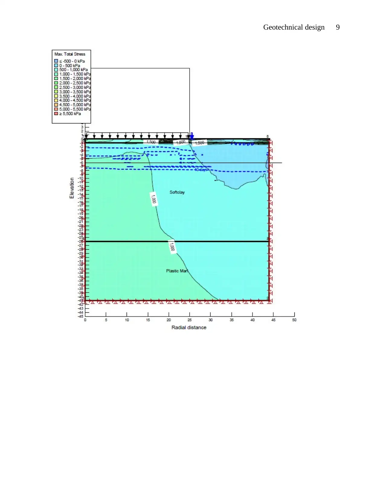
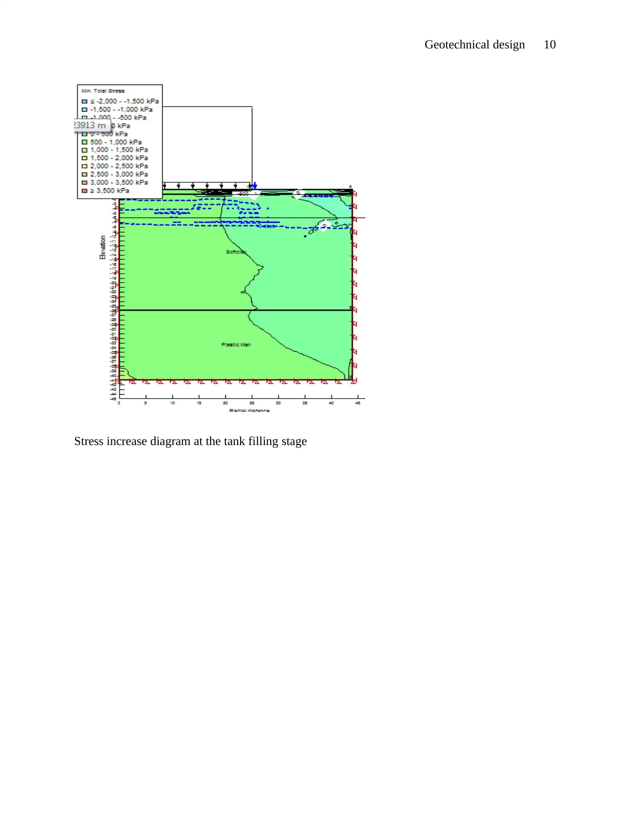
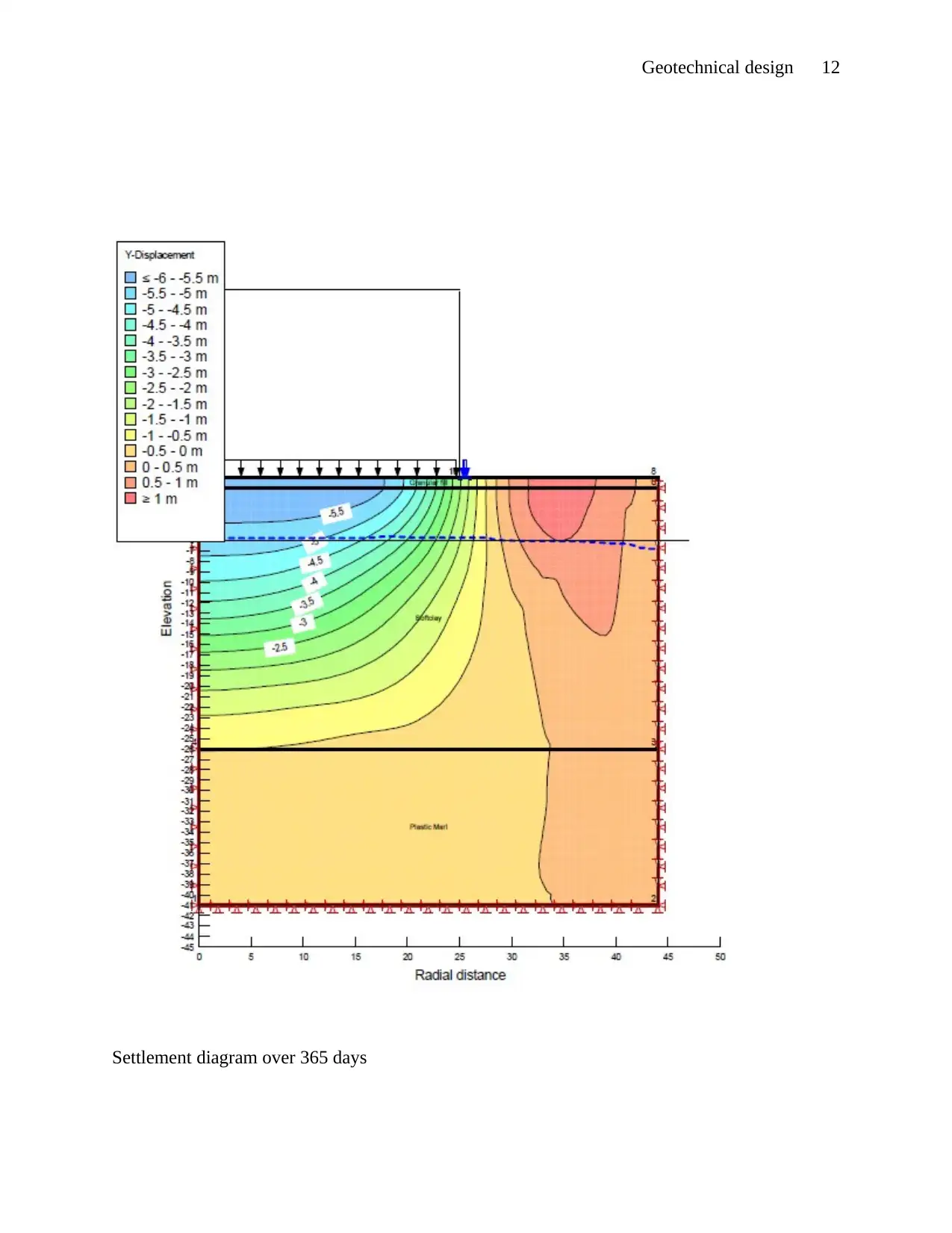
This report presents a geotechnical design analysis of a cylindrical water tank foundation using numerical methods. The study investigates the stresses and displacements in the soil mass due to the applied loading, considering a three-dimensional scenario simplified to a two-dimensional finite mesh. The analysis accounts for factors such as the initial soft clay conditions, the addition of granular fill, and the staged construction process, including foundation placement, tank welding, and water filling. The software Geostudio is utilized to perform Finite Element Analysis (FEA) and simulate stress deformation, pore water pressure, and slope stability. Objectives include determining settlement diagrams, changes in stresses, and excess pore water pressure. The methodology involves setting up the working template in Geostudio, defining material properties, assigning boundary conditions, and simulating the staged construction process. The results include settlement diagrams, stress increase diagrams, and excess pore water pressure diagrams at different stages, providing insights into the behavior of the soil and the foundation under the applied loads.

Geotechnical design 1
GEOTECHNICAL DESIGN
By (Name)
Course
Professor’s name
University name
City, State
Date of submission
GEOTECHNICAL DESIGN
By (Name)
Course
Professor’s name
University name
City, State
Date of submission
Paraphrase This Document
Need a fresh take? Get an instant paraphrase of this document with our AI Paraphraser

Geotechnical design 2
Introduction
This study deals with the stresses and displacements in a soil mass due to the applied
loading. The analysis and simulation of this case is three dimension. For the case of two
dimensions, the normal stresses and shear stresses in the x and z directions, where the rate of
changes of the normal stresses are ∂ σ x /∂ x , ∂ σ z /∂ z and shear stressesare ∂ τ xz /ϑx and ϑ τ zx /ϑz
(Smith, 2014). By the equating moments about the axis. Due to the applied loading, the soil mass
will be displaced relative to the axes and to one another.
The ground initial conditions the soil is soft clay and underneath the plastic marl. The
water table is 6m below the datum. Granular fill is added and compacted to a depth of 1m. A
flexible steel base is placed in day 2 and the tank is welded on the next day. Then fill with water
up to 70% for the next 7 days.
The software used to perform the analysis and simulation should perform Finite Element
Analysis (FEA) and Numerical Analysis. In this case, the recommended one is Geostudio.
Geostudio is suitable to perform and simulate the geotechnical analysis. It performs the stress
deformation, initial state analysis, couple stress or the pore water Pressure, stress redistribution,
Volume change, seepage analysis, dynamic analysis, and slope stability analysis (Yamin, et al,
2017).
Objectives
Determine and drawing the settlement diagram under the foundation.
Determine and draw the changes in stresses
Draw the excess pore water pressure diagram

Geotechnical design 3
Literature Review
We are required to perform a stress-deformation in consideration of pore-water pressure
and without that is from the applied loads. The computation of these changes are below the
flexible foundation of a circular tank with water.
Deformation Analysis
For the purpose of deformation analysis in the Geostudio is perform by the SIGM/W. the
deformation can be due to foundations, embankments, excavations and tunnels (Barnes, 2016).
The case study is a water-filled tank on a flexible foundation on the ground surface.
The Excess pore-water pressures
The effect of couple stresses will be considered due to the fill placement and even in
some cases the applied loading (Chehade & Shahrour, 2008). For the slope stability
consideration, the excess pore-water pressures computations done by the SIGMA/W from the
import into SLOPE/W. the bilateral collaboration of SLOPE/W and SIGMA/W allows the slope
stability analysis and couple stresses to be performed with ease.
Stage construction
Most of the soil regions are constructed at different stages. The Geostudio provides a
feature that allows different stages to be processed over time in a single project file. This is
achieved by automatically linking multiple analyses together on a single continuum time.
Modeling in Geotechnical Engineering
In this field, numerical models are considered over the physical modeling since the setup
is quicker (Barnes, 2016) and (Paice, et al 1996). The modeling will provide information and
⊘ This is a preview!⊘
Do you want full access?
Subscribe today to unlock all pages.

Trusted by 1+ million students worldwide

Geotechnical design 4
results at any point within the cross-section and accommodate a wide variety of boundary
conditions. According to Professor Burland, he emphasized on the three fundamental
components of soil mechanics which are the ground profile, the soil behavior and modeling
(Indraratna, et al., 2015). The relations of these components are illustrated with the following
Figure 1: Soil mechanic triangle (Indraratna, et al., 2015)
The soil behavior component is gotten by performing laboratory test, in situ and field test.
The profile involves the site characterization while modeling may be conceptual, analytical and
simulation (Indraratna, et al 2015).
Methodology
The problem is a three-dimension, therefore being symmetric about a vertical axis the
analysis will be performed with a two-dimensional finite mesh.
Paraphrase This Document
Need a fresh take? Get an instant paraphrase of this document with our AI Paraphraser

Geotechnical design 5
Setting working Template
Once I open the Geostudio, clicked on open a new project. Created a new project from
the default setting. Selecting the Sigma/W and the first is the in-situ type of analysis. Set the
initial pore-Water Pressure condition from the Water-Table. Set time to 0 days.
Setting of units and the scale command by clicking set in the menu bar. Setting the
engineering unit to SI units (metric). Time in days, Force in Kilo Newton. The view select
axisymmetric. The axisymmetric changes the three-dimension to two dimensions. Only one
plane is represented by the circumferential view since the same at any vertical plane (Paice, et
al., 1996). Selecting the axisymmetric view and the central angle to be 360/2 π =57.29578.
Scale selected is within the paper size to fit the whole geometry of interest.
Sketch the axes to fit the dimension. The elevation should be within the range 25m and -
45m, the radial axis (horizontal axis) to be 0- 40m, where at 0 forms the vertical axis that gives
the symmetry axis. Sketch half the diagram from the point of symmetry (Shahba & Soltani,
2016).
Stage 1
KeyIn the materials assigning the properties by adding the material. The material
categories for is effective-drained parameters for both the soft clay and plastic marl. Soft clay
initial selected the elastic –plastic (effective), E-modulus is 97000kPa, cohesion selects constant
27kpa, unit weight 18.8 kN /m3, passion’s Ratio 0.35, Phi φ=14 ° . The Plastic marl in-situ
material, the E-modulus is 30000kPa, cohesion 90kPa, Poisson’s Ratio is 0.30, phi φ=15 °. Set
and draw the initial water table. Draw the materials assign the material as shown. Set the

Geotechnical design 6
boundary condition s, at the axis of symmetry fixed X, the horizontal axis at the bottom of the
profile fix X-Y directions and the right side fix X-Y direction.
Stage 2 (0-1 day)
KeyIn analysis by cloning the in-situ (stage 1), the name is Granular fill compacting, and
make in-situ the parent. The analysis type is coupled Stress/PWP and time to be 1 day.
KeyIn the materials, clone Soft clay in-situ and plastic Marl in-situ, name them soft clay
and plastic marl. The material category changes them to effective Parameters w/ PWP change
and the model to Elastic-Plastic (w/ PWP change). Add the hydraulic properties as per the data
being provided (Smith, 2014). Added Granular fill with properties; Effective Parameters/ PWP
change as the material category and Elastic-Plastic (w/ PWP change) as the model. Assign the E-
modulus, cohesion constants, Poisson’s Ratio and Phi angle as data provided. Draw and assign
materials as the profile being provided.
Stage 3 (1-3 day)
This stage is assumed to be done in two stages each day. It involves laying of the
foundation. Therefore keyIn analysis clone stage 2 (placing fills). Make stage 2, placing of fills
the parent. The duration is 2 days and has 2 steps, foundation laying and welding of the tank
(Vereecken, et al., 2016).
The boundary conditions are as previous but introduce a node at (0, 26m). Add plate
boundary condition by with stress option of X-Y stress. The stress is in the Y-stress which is
given by
γ
thickness= 78.5
0.002 =−0.157 kPa
⊘ This is a preview!⊘
Do you want full access?
Subscribe today to unlock all pages.

Trusted by 1+ million students worldwide

Geotechnical design 7
Add the base boundary condition line with coordinate (0, 0) and (26, 0).
Stage 4
Filing of the tank with water up to 70%. Add the analysis by cloning foundation on
granular analysis. The parent of the analysis is the Foundation on Granular, the duration is 7 days
and Analysis type is PWP.
The material used is that from the stage 2. The boundary conditions are those of stage 2.
Addition of tank water pressure as a boundary condition. The stress will be in the X-Y, where
the Y stress is negative (-) calculated as
γH × 0.7=10× 18 ×0.7=−126 kPa
Applied the water tank pressure boundary condition to a radius of the tank (0-25m).
Solving
Run the solve Manager of all the analysis to give the results.
Paraphrase This Document
Need a fresh take? Get an instant paraphrase of this document with our AI Paraphraser

Geotechnical design 8
Results and Finding
The settlement diagram over the tank at the filling stage
Results and Finding
The settlement diagram over the tank at the filling stage

Geotechnical design 9
⊘ This is a preview!⊘
Do you want full access?
Subscribe today to unlock all pages.

Trusted by 1+ million students worldwide

Geotechnical design 10
Stress increase diagram at the tank filling stage
Paraphrase This Document
Need a fresh take? Get an instant paraphrase of this document with our AI Paraphraser

Geotechnical design 11
Excess pore-water pressure diagrams at the filling stage

Geotechnical design 12
Settlement diagram over 365 days
⊘ This is a preview!⊘
Do you want full access?
Subscribe today to unlock all pages.

Trusted by 1+ million students worldwide
1 out of 16
Related Documents

Your All-in-One AI-Powered Toolkit for Academic Success.
+13062052269
info@desklib.com
Available 24*7 on WhatsApp / Email
Unlock your academic potential
Copyright © 2020–2025 A2Z Services. All Rights Reserved. Developed and managed by ZUCOL.