Gherkin Replica Project: Detailed Construction Method Statement
VerifiedAdded on 2023/06/13
|9
|1733
|358
Project
AI Summary
This document provides a detailed method statement for the construction of a Gherkin replica, outlining the sequence of work from superstructure assembly and formwork prefabrication to excavation, hard-core laying, concrete pouring, and backfilling. It includes setting out drilling positions, erecting levels, fixing the floor, and placing the dome, with specific instructions and safety precautions for each stage. The document also features a risk assessment identifying significant hazards like falls, scaffolding issues, collapse, moving objects, and noise, along with suggested preventative measures. A plant schedule is included, listing necessary equipment such as excavators, concreting plants, compaction plants, and cranes. Concluding with a list of references, this document provides a comprehensive overview of the Gherkin replica construction process. Find more solved assignments and past papers on Desklib.
GHERKIN REPLICA PROJECT DESCRIPTIVE
STATEMENT
Name:
Course Title:
Course Code
Date of Submisson
1
STATEMENT
Name:
Course Title:
Course Code
Date of Submisson
1
Paraphrase This Document
Need a fresh take? Get an instant paraphrase of this document with our AI Paraphraser
Table of Contents
1.0 Introduction...................................................................................................................................3
2.0 Sequence of work in building the Gherkin Replica:...................................................................3
Superstructure assembling...................................................................................................................3
Formwork and reinforcement Prefabrication.....................................................................................3
Setting out..............................................................................................................................................4
Excavation..............................................................................................................................................4
Hard-core and Blinding........................................................................................................................5
Placing formwork & Pouring concrete................................................................................................5
Removing formwork..............................................................................................................................5
Backfilling..............................................................................................................................................6
Setting out drilling positions.................................................................................................................6
Erecting level ‘1 and 3’..........................................................................................................................6
Fixing the floor.......................................................................................................................................7
Erecting ‘L3 to L5’ and ‘L5 to L7’.......................................................................................................7
Placing the Dome...................................................................................................................................7
3.0 A Risk Assessment For The Significant Hazards Involved In The Gherkin Replica Project........8
4.0 Plant schedule......................................................................................................................................8
References...................................................................................................................................................9
2
1.0 Introduction
Gherkin replica is a building which is situated at the very Centre of the of the CBD of
London, England. In view of the structure of the Gherkin replica building, the below is a
descriptive method statement of a how to build the Gherkin replica safely.
2.0 Sequence of work in building the Gherkin Replica:
Superstructure assembling
i. The process of Assembling of the core and the diagrid is to start in corresponding with
the setting out.
ii. Hop ups should to put on ground which is very much stable, when getting to the highest
point of the level.
iii. The gathering is to be done in understanding to the illustrations.
Formwork and reinforcement Prefabrication
It is a necessary that the Formwork and fortification for both the core and the ring to be present.
The pens for fortification are to be amassed on timber, this is in order to make it easy and safe
during lifting
3
⊘ This is a preview!⊘
Do you want full access?
Subscribe today to unlock all pages.
Trusted by 1+ million students worldwide
Setting out.
i. Set out the excavation immediately you land on the site
ii. When need be, it’s advisable to make use of the cable avoidance tools for scanning the
cables
Excavation
i. Excavate the region which are inside the exhuming lines. Ensured Banksman will be
required to flag the excavator agent.
ii. The material which is excavated must be put no less than a meter far from the edge of
uncovering.
iii. During the process of excavation, wellbeing and safety precautionary measures must be
taken, e.g. partition hindrances, and cautioning signs.
iv. Check the level of excavation time to time, this is to stay away from over excavation.
v. Upon achieving the coveted profundity, level the ground equitably and reduced.
Hard-core and Blinding
i. Make sure that the hard-core which is used for the ring beam and the foundation is filled
with thick material of about 300mm then its compacted
4
Paraphrase This Document
Need a fresh take? Get an instant paraphrase of this document with our AI Paraphraser
ii. Fill the top of the hard-core with concrete layer of about 50mm
Placing formwork & Pouring concrete.
i. Mark the core and the ring foundation layout, after curing the binding
ii. Then place the support of the core and the ring beam on the layout which was
marked
iii. Arrange the formwork temporarily around the central core which is supported
iv. The inner shuttering for the ring beam must be placed in accordance to the
drawings. Followed by placing the outer shuttering.
v. After clearing the area with jet washers, then the concrete is to be poured in layers
for both core and ring. Each layer is to be compacted, using vibrating pokers.
Removing formwork
The formwork must be removed with a lot of care and at the moment this is cured, the de-nailing
of the concrete should be done in order to shun from accidents
Backfilling
i. The trench which is around the ring beam which was to supposed to be backfilled with
the materials which was excavated
5
ii. The vegetation or the bolder are needed to be removed from the materials for backfilling
iii. The backfilling materials are then compacted to the level which is standard
Setting out drilling positions
i. Erect piece by piece the steel work from the foundation to L1 in order to permit students
from the precise shape.
ii. Mark the positions of the column of the ground with the total station on the foundation
made from concrete.
iii. Check the positions which are marked for accuracy purposes, then drill, then bolt using
M12 type anchor bolt
iv. Wear safety goggles when you are drilling or you are near the site. The use of the dust is
also advised.
v. The “offsite” manufacturing of the floor cassettes must be in performed parallel to the
erection.
Erecting level ‘1 and 3’
i. Call the crane on the site for it to erect the external diagrid. The core which is also to be
erected on top of the first splice L1 also supposed to be erected by the crane. Standing
below the lifted steel should be avoided
ii. Attach the bottom bolt of the core at 1.2m height.
iii. Use the hop ups to reach and fix the diagrid.
iv. The rods which are between the core and the diagrid are supposed to be adjusted, in order
to hold the diagrid and to adjust the diagrid accordingly
6
⊘ This is a preview!⊘
Do you want full access?
Subscribe today to unlock all pages.
Trusted by 1+ million students worldwide
Fixing the floor
i. The floor cassettes are to be lifted by crane and positioned at ‘L3’ Upon erecting the
superstructure up to (L3),
ii. Working from the hop ups the floor cassettes are to be bolted to the core and the diagrid.
iii. Standing below the lifted components should be avoided
iv. The toe boards should be prefixed to the cassettes.
v. Suitable person is to fix the ladder into the core and also fixes the cable handrails.
vi. Follow the above procedure for placing the other 2 floors.
Erecting ‘L3 to L5’ and ‘L5 to L7’
i. Follow the above procedure for erecting the rest of the levels.
ii. Adhere to all safety procedures, as the risk of fall is increasing.
Placing the Dome.
i. The last piece of the superstructure which is the arch is to be lifted and situated on 'L7'.
ii. The uncommon plates is to be utilized to discharge the crane (no compelling reason to
move up, and discharge.)
7
Paraphrase This Document
Need a fresh take? Get an instant paraphrase of this document with our AI Paraphraser
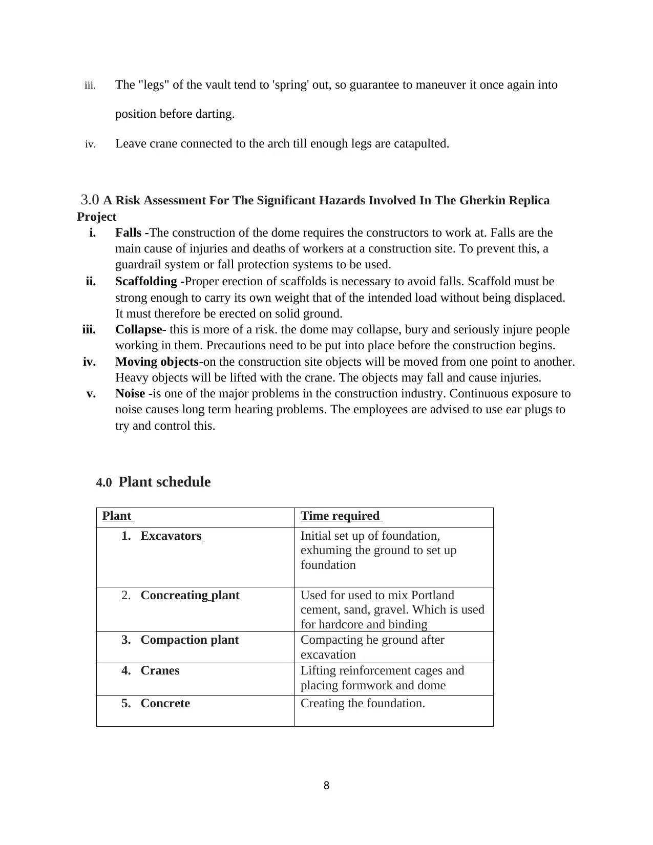
iii. The "legs" of the vault tend to 'spring' out, so guarantee to maneuver it once again into
position before darting.
iv. Leave crane connected to the arch till enough legs are catapulted.
3.0 A Risk Assessment For The Significant Hazards Involved In The Gherkin Replica
Project
i. Falls -The construction of the dome requires the constructors to work at. Falls are the
main cause of injuries and deaths of workers at a construction site. To prevent this, a
guardrail system or fall protection systems to be used.
ii. Scaffolding -Proper erection of scaffolds is necessary to avoid falls. Scaffold must be
strong enough to carry its own weight that of the intended load without being displaced.
It must therefore be erected on solid ground.
iii. Collapse- this is more of a risk. the dome may collapse, bury and seriously injure people
working in them. Precautions need to be put into place before the construction begins.
iv. Moving objects-on the construction site objects will be moved from one point to another.
Heavy objects will be lifted with the crane. The objects may fall and cause injuries.
v. Noise -is one of the major problems in the construction industry. Continuous exposure to
noise causes long term hearing problems. The employees are advised to use ear plugs to
try and control this.
4.0 Plant schedule
Plant Time required
1. Excavators Initial set up of foundation,
exhuming the ground to set up
foundation
2. Concreating plant Used for used to mix Portland
cement, sand, gravel. Which is used
for hardcore and binding
3. Compaction plant Compacting he ground after
excavation
4. Cranes Lifting reinforcement cages and
placing formwork and dome
5. Concrete Creating the foundation.
8
References
Assaf, S.A., Al-Khalil, M. and Al-Hazmi, M., 2008. Causes of delay in large building construction
projects. Journal of management in engineering, 11(2), pp.45-50.
Abd El-Razek, M. E., Bassioni, H. A., & Mobarak, A. M. (2009). Causes of delay in building construction
projects in Egypt. Journal of construction engineering and management, 134(11), 831-841.
Kymmell, W., 2008. Building Information Modeling: Planning and Managing Construction Projects with 4D
CAD and Simulations (McGraw-Hill Construction Series): Planning and Managing Construction Projects
with 4D CAD and Simulations. McGraw Hill Professional.
Muhwezi, L., Acai, J. and Otim, G., 2014. An assessment of the factors causing delays on building
construction projects in Uganda. International Journal of Construction Engineering and
Management, 3(1), pp.13-23.
Seppänen, O., 2009. Empirical research on the success of production control in building construction
projects. A PhD thesis, Department of Structural Engineering and Building Technology, Helsinki
University of Technology, Finland.
Kaliba, C., Muya, M. and Mumba, K., 2009. Cost escalation and schedule delays in road construction
projects in Zambia. International Journal of Project Management, 27(5), pp.522-531.
Enshassi, A., Al-Najjar, J. and Kumaraswamy, M., 2009. Delays and cost overruns in the construction
projects in the Gaza Strip. Journal of Financial Management of Property and Construction, 14(2), pp.126-
151.
9
⊘ This is a preview!⊘
Do you want full access?
Subscribe today to unlock all pages.
Trusted by 1+ million students worldwide
1 out of 9

Your All-in-One AI-Powered Toolkit for Academic Success.
+13062052269
info@desklib.com
Available 24*7 on WhatsApp / Email
![[object Object]](/_next/static/media/star-bottom.7253800d.svg)
Unlock your academic potential
Copyright © 2020–2026 A2Z Services. All Rights Reserved. Developed and managed by ZUCOL.