Comprehensive Study of Gigabit Passive Optical Networks (GPONs)
VerifiedAdded on 2023/04/26
|60
|17435
|475
Report
AI Summary
This report provides a detailed exploration of Gigabit Passive Optical Networks (GPON) technology, covering its architecture, benefits, design, components, services, and applications. It begins with an introduction to passive optical networks, discussing their architectures, protocols, and standards. The report delves into the specifics of GPON, including its advantages, design considerations, and key elements such as the Optical Line Terminal (OLT) and Optical Network Unit (ONU). It also addresses bandwidth allocation, Quality of Service (QoS), and Service Level Agreements (SLAs). Furthermore, the report examines the technical aspects of GPON, including the Physical Medium-Dependent Layer (PMD) and Transmission Convergence Layer, as well as alternative technologies like Ethernet PON (EPON). Finally, it discusses the challenges and evolution trends in next-generation PON deployment, providing a comprehensive understanding of GPON technology and its future directions.

Gigabit Passive Optical Network (GPON)
Student’s name,
Student ID,
Course
Project supervisor.
Student’s name,
Student ID,
Course
Project supervisor.
Paraphrase This Document
Need a fresh take? Get an instant paraphrase of this document with our AI Paraphraser
Table of Contents
1 Introduction..............................................................................................................................4
2 Introduction to Passive optical network..................................................................................4
2.1 The concept of Passive optical networks..........................................................................4
2.2 Passive Optical Networks Architectures and Protocols....................................................6
2.3 PON Architectures............................................................................................................6
2.3.1 Network Dimensioning and Bandwidth....................................................................8
2.3.2 Power Budget.............................................................................................................8
2.3.3 Testing Optical Splitters............................................................................................8
2.3.4 PON Packet Encapsulation and Format...................................................................10
2.4 PON Standards Deployment and History.......................................................................10
2.5 FTTx Deployment...........................................................................................................10
3 Introduction to Gigabit Passive Optical Network (GPON)...................................................12
3.1 Benefits of GPON Technology.......................................................................................13
3.2 GPON Design.................................................................................................................14
3.3 Components of the GPON FTTH Access Network........................................................15
3.4 Overview of GPON.........................................................................................................16
3.4.1 GPON Elements.......................................................................................................16
3.4.2 Quality of Services (QoS)........................................................................................17
3.5 GPON Services and Applications...................................................................................19
3.5.1 Residential Service..................................................................................................19
3.5.2 Advanced Services over GPON...............................................................................20
3.6 Bandwidth Upgrade........................................................................................................23
3.7 The importance of allocating bandwidth dynamically in a GPON network...................24
3.8 Static Bandwidth Allocation...........................................................................................26
3.9 Service Level Agreement (SLA) and Oversubscription.................................................27
3.10 Gigabit Passive Optical Network (GPON)..................................................................30
3.10.1 GPON Physical Medium-Dependent Layer (GPON PMD)....................................30
3.11 GPON Transmission Convergence Layer...................................................................32
3.11.1 Downstream Frame Convergence of GPON Transmission.....................................32
3.11.2 Upstream Frame Convergence of GPON transmission...........................................33
3.11.3 GPON Encapsulation Method (GEM).....................................................................34

3.11.4 GPON Downstream Encryption Method.................................................................36
3.12 Ethernet PON..............................................................................................................36
3.12.1 EPON Architecture..................................................................................................37
3.12.2 EPON Point-to-Multipoint MAC Control...............................................................40
4 PON Deployment challenges in the Next-Gen......................................................................42
4.1 Evolving Standards.........................................................................................................42
4.2 New Challenges..............................................................................................................44
4.3 The Next-generation PON Evolution Trend Discussion.................................................46
5 Conclusion.............................................................................................................................50
6 References List......................................................................................................................53
7 Appendix A: Project Schedule...............................................................................................56
8 Appendix B: Gantt Chart.......................................................................................................57
⊘ This is a preview!⊘
Do you want full access?
Subscribe today to unlock all pages.
Trusted by 1+ million students worldwide
1 Introduction
Gigabit Passive Optical Networks (GPON) is a technology which has been adopted in
networking with the aim of offering significant cost reduction in network operations (Kumar,
2014). Nevertheless, large scale GPON needs a massive investment in infrastructure and
equipment. Before deploying a large scale GPON it is important to acquire smaller GPON
systems and test them to determine its suitability. This study will focus on the concept of passive
optical networks and their typical architectures, typical services and the operation principle of a
GPON, calculation of splitting power loss of optical power splitters, and analysis of the optical
power budget of a GPON.
2 Introduction to Passive optical network
Passive optical network technologies such as GPON and Ethernet PON are currently the
most used access network technologies. PON is made up of a passive optical splitter, central
optical line terminal (OLT), and a single optical network unit terminal at the client premises
connected in a tree topology (Kazovsky, 2011). In the past, PONs used TDM- time division
multiplexing for medium sharing in the case of point to multipoint connections. The OLT
broadcasts frames towards the ONUs, however, in the upstream in order to avoid collisions an
arbitration mechanism is required when ONUs is sending frames to the OLT (Hood and Trojer,
2012).
2.1 The concept of Passive optical networks
An optical network is a kind of a network that has both passive and active elements.
Active elements are in switches, repeaters, in central office, at customer residence among other
locations. However, this section will focus on the concept of passive optical networks which has
no active elements between the customer and the central office (Zhang, 2010). Additionally,
passive devices require no power supply and their main purpose is to direct the traffic signals in
specific optical wavelengths. Services such as data, video, and voice can be implemented easily
using varying wavelengths. One equipment that is mostly used is the GPON equipment. Passive
optical networks do not contain any active optical elements along the network path. The figure
Paraphrase This Document
Need a fresh take? Get an instant paraphrase of this document with our AI Paraphraser
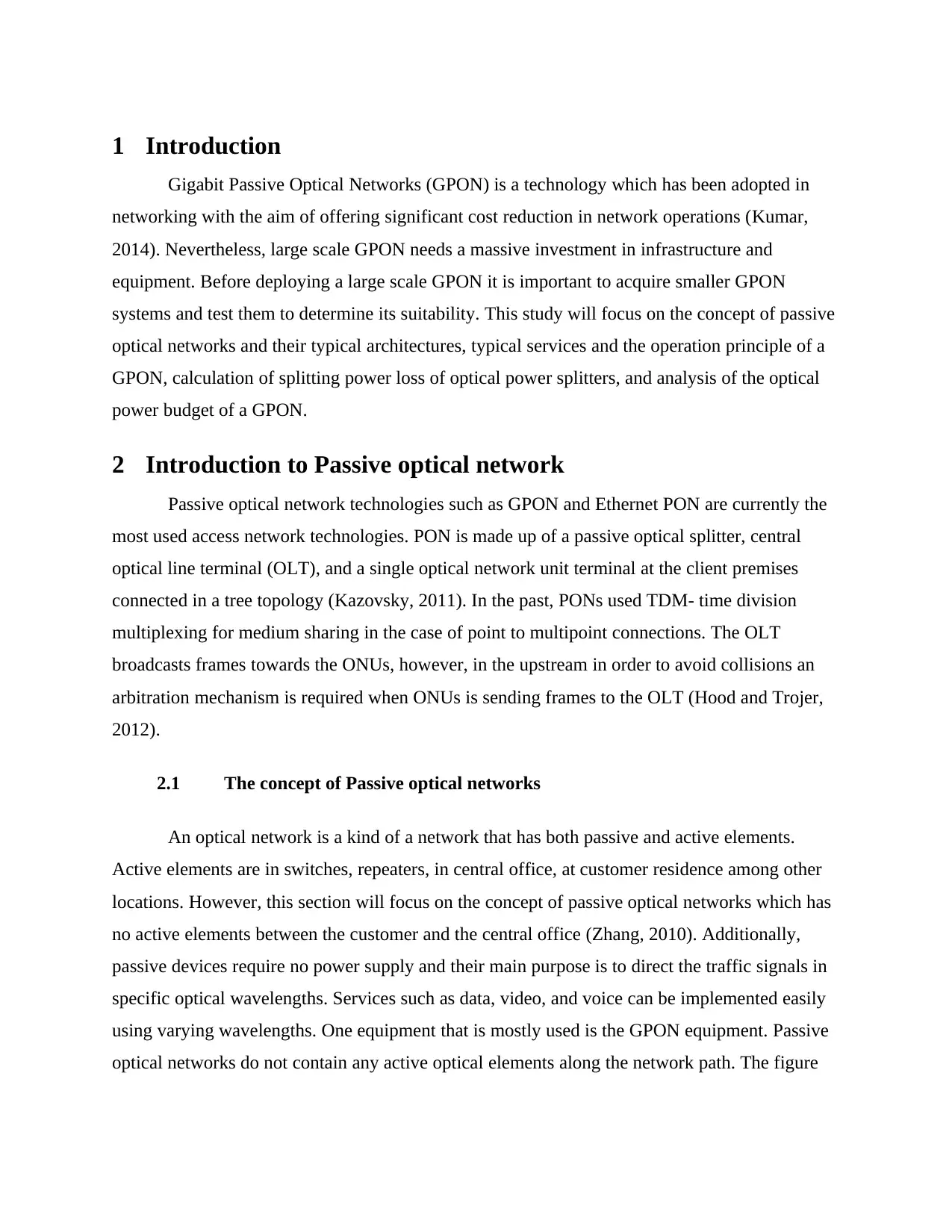
below shows how multiple subscribers are connected to the central office using a fiber optic
network.
Figure 1: Connecting Multiple Users to the Central Office using Fiber Optic (Weinstein, Luo and
Wang, 2012)
The central office may contain other multiple devices like video-on-demand servers,
asynchronous transfer mode switches (ATM), and public switched telephone network switches
(PSTN), Backup systems, and Ethernet switches among other components (Weinstein, Luo and
Wang, 2012).
Passive optical power splitter is located near the customer premises and one single-mode
fiber cable is used to connect it to the central office. The splitting device is used to divide the
signal into several paths making it easy to determine the power level of each subscriber by
dividing the splitter power (P) by number of paths (N): Power level=Splitter power (P)/Number
of paths (N). In cases where there is need to have different splitting ratios, multiple splitters can
be used in the network path. It is possible to divide a path up to 64 paths each having a single-
mode fiber connected to every serving equipment or building. The distance between the
customer and the central office could be up to 20 kilometers in passive optical network scenario,
while having active elements only in the end terminals and the central office (Keiser, 2015).
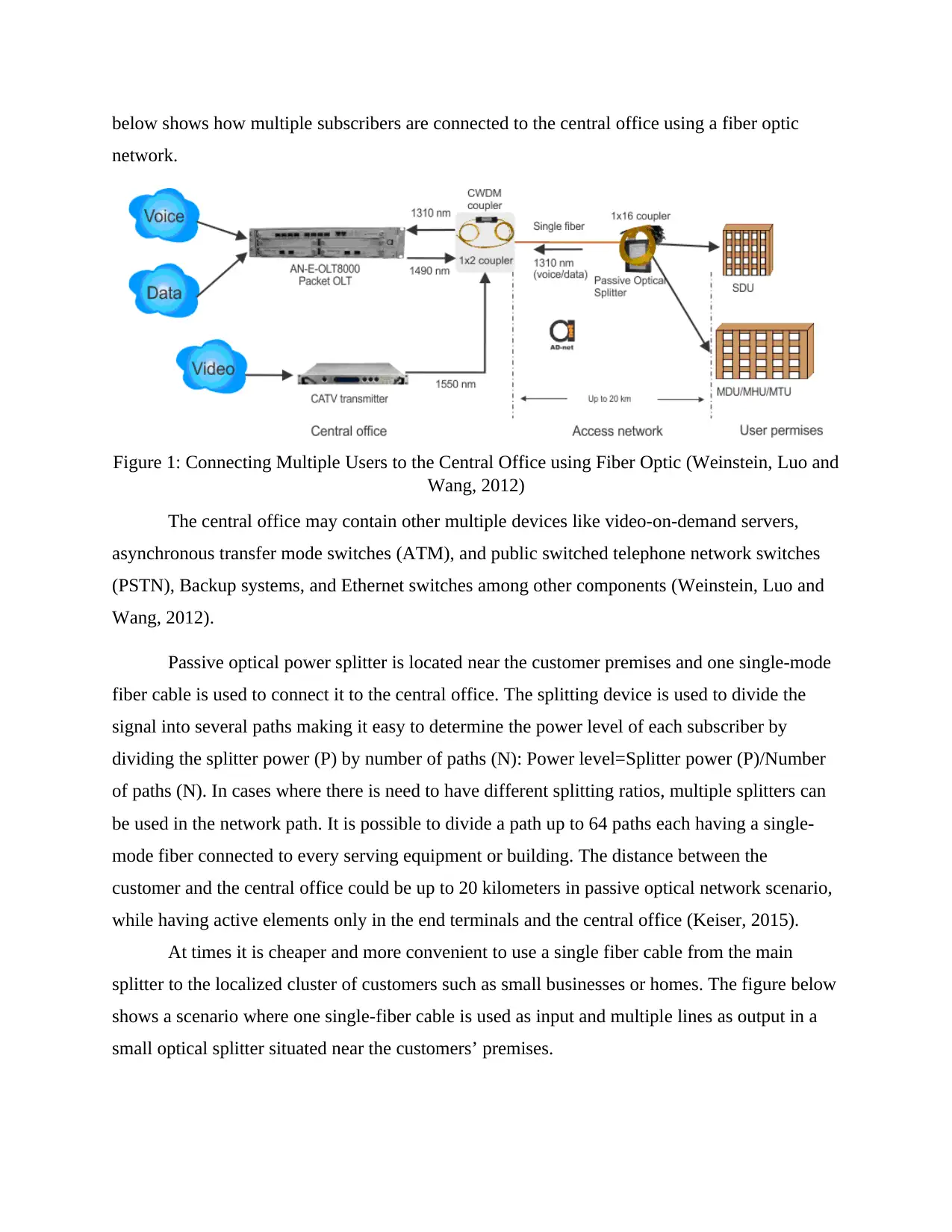
At times it is cheaper and more convenient to use a single fiber cable from the main
splitter to the localized cluster of customers such as small businesses or homes. The figure below
shows a scenario where one single-fiber cable is used as input and multiple lines as output in a
small optical splitter situated near the customers’ premises.
network.
Figure 1: Connecting Multiple Users to the Central Office using Fiber Optic (Weinstein, Luo and
Wang, 2012)
The central office may contain other multiple devices like video-on-demand servers,
asynchronous transfer mode switches (ATM), and public switched telephone network switches
(PSTN), Backup systems, and Ethernet switches among other components (Weinstein, Luo and
Wang, 2012).
Passive optical power splitter is located near the customer premises and one single-mode
fiber cable is used to connect it to the central office. The splitting device is used to divide the
signal into several paths making it easy to determine the power level of each subscriber by
dividing the splitter power (P) by number of paths (N): Power level=Splitter power (P)/Number
of paths (N). In cases where there is need to have different splitting ratios, multiple splitters can
be used in the network path. It is possible to divide a path up to 64 paths each having a single-
mode fiber connected to every serving equipment or building. The distance between the
customer and the central office could be up to 20 kilometers in passive optical network scenario,
while having active elements only in the end terminals and the central office (Keiser, 2015).
At times it is cheaper and more convenient to use a single fiber cable from the main
splitter to the localized cluster of customers such as small businesses or homes. The figure below
shows a scenario where one single-fiber cable is used as input and multiple lines as output in a
small optical splitter situated near the customers’ premises.
Figure 2: One single-fiber cable is used input and multiple lines output (Weinstein, Luo and
Wang, 2012)
2.2 Passive Optical Networks Architectures and Protocols
Passive optical networks (PON) have evolved to be one of the matured access
technologies that provides broad area coverage, flexibility, and cost-effective sharing of network
components and fiber links in response to the growing bandwidth demand and advanced network
services from enterprise clients and residential consumers. Both IEEE and ITU have provided
solutions that are standardized for PONs with line rates of gigabit per second (Alshaer, Shubair
and Alyafei, 2011).
ITU-T rectified Gigabit Passive Optical Network (GPON) in the G.984.x proposals to
facilitate gigabit rates and a mix of ethernet services, ATM, and TDM, and to improve security.
However, it is important to point out that there exists some difference between the Ethernet
passive optical network (EPON) and GPON in spite of having similar optical transceiver budget
and transmission wavelength, they differ in terms of OAM capabilities, transmission
convergence (TC), physical medium-dependent layer (PDM), and MAC layer.
2.3 PON Architectures
⊘ This is a preview!⊘
Do you want full access?
Subscribe today to unlock all pages.
Trusted by 1+ million students worldwide
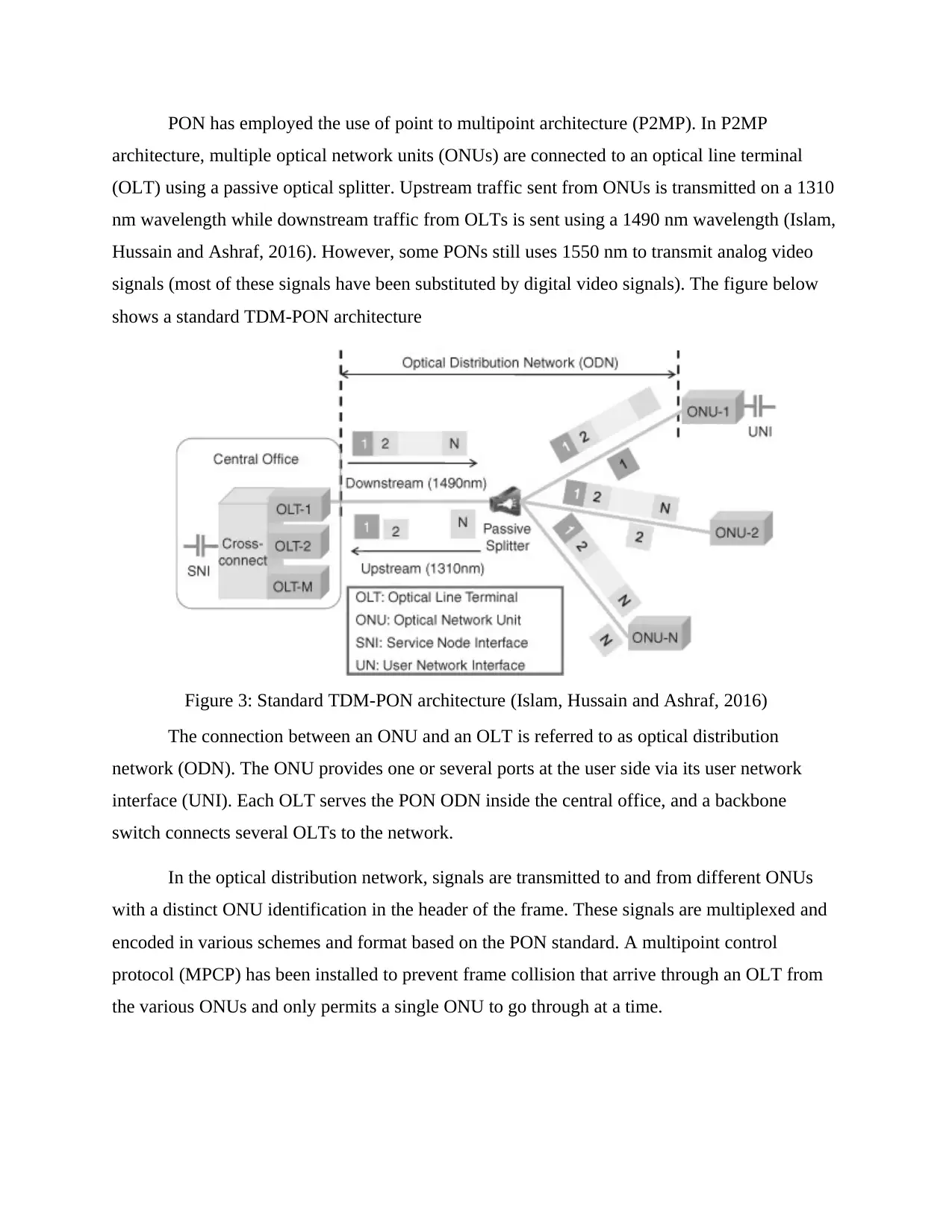
PON has employed the use of point to multipoint architecture (P2MP). In P2MP
architecture, multiple optical network units (ONUs) are connected to an optical line terminal
(OLT) using a passive optical splitter. Upstream traffic sent from ONUs is transmitted on a 1310
nm wavelength while downstream traffic from OLTs is sent using a 1490 nm wavelength (Islam,
Hussain and Ashraf, 2016). However, some PONs still uses 1550 nm to transmit analog video
signals (most of these signals have been substituted by digital video signals). The figure below
shows a standard TDM-PON architecture
Figure 3: Standard TDM-PON architecture (Islam, Hussain and Ashraf, 2016)
The connection between an ONU and an OLT is referred to as optical distribution
network (ODN). The ONU provides one or several ports at the user side via its user network
interface (UNI). Each OLT serves the PON ODN inside the central office, and a backbone
switch connects several OLTs to the network.
In the optical distribution network, signals are transmitted to and from different ONUs
with a distinct ONU identification in the header of the frame. These signals are multiplexed and
encoded in various schemes and format based on the PON standard. A multipoint control
protocol (MPCP) has been installed to prevent frame collision that arrive through an OLT from
the various ONUs and only permits a single ONU to go through at a time.
Paraphrase This Document
Need a fresh take? Get an instant paraphrase of this document with our AI Paraphraser
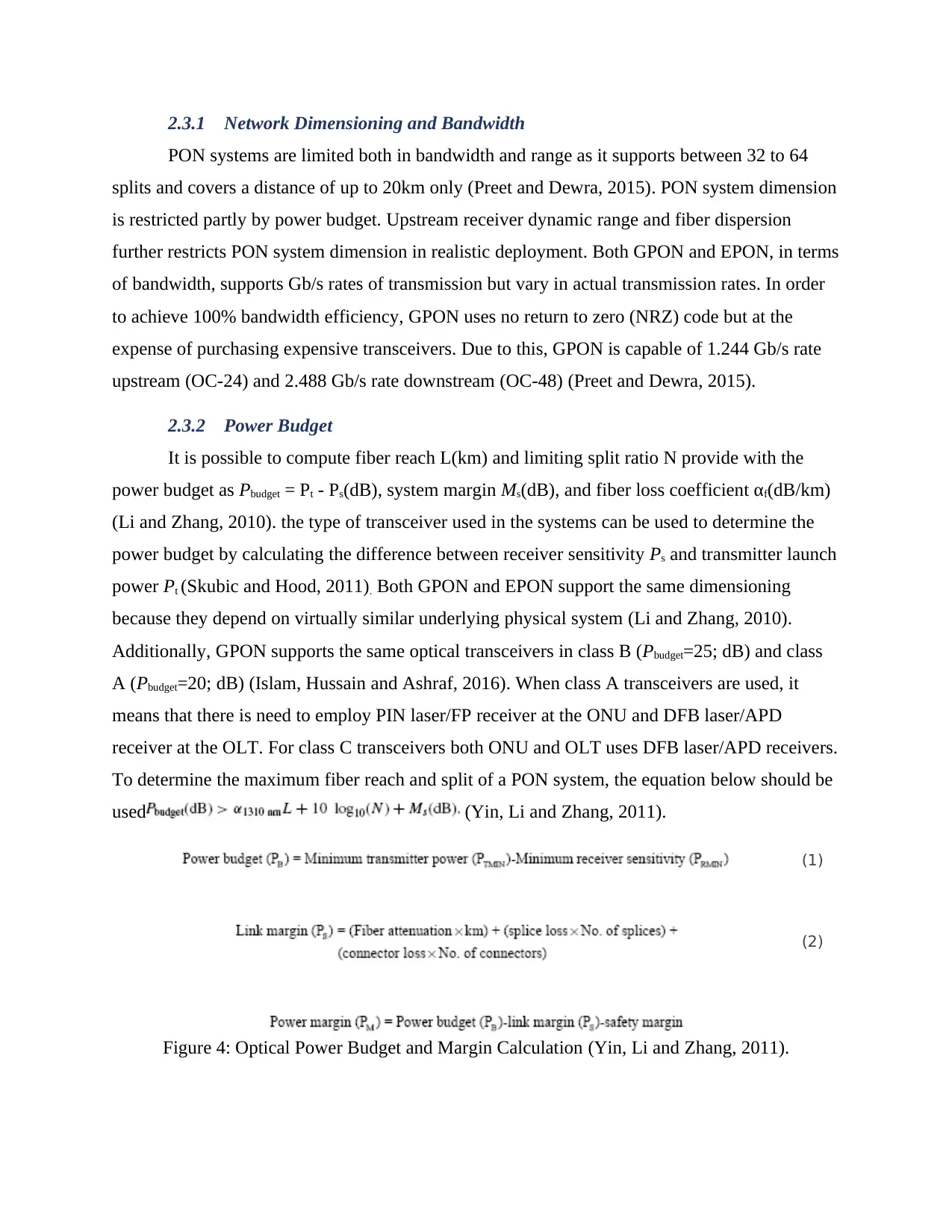
2.3.1 Network Dimensioning and Bandwidth
PON systems are limited both in bandwidth and range as it supports between 32 to 64
splits and covers a distance of up to 20km only (Preet and Dewra, 2015). PON system dimension
is restricted partly by power budget. Upstream receiver dynamic range and fiber dispersion
further restricts PON system dimension in realistic deployment. Both GPON and EPON, in terms
of bandwidth, supports Gb/s rates of transmission but vary in actual transmission rates. In order
to achieve 100% bandwidth efficiency, GPON uses no return to zero (NRZ) code but at the
expense of purchasing expensive transceivers. Due to this, GPON is capable of 1.244 Gb/s rate
upstream (OC-24) and 2.488 Gb/s rate downstream (OC-48) (Preet and Dewra, 2015).
2.3.2 Power Budget
It is possible to compute fiber reach L(km) and limiting split ratio N provide with the
power budget as Pbudget = Pt - Ps(dB), system margin Ms(dB), and fiber loss coefficient αf(dB/km)
(Li and Zhang, 2010). the type of transceiver used in the systems can be used to determine the
power budget by calculating the difference between receiver sensitivity Ps and transmitter launch
power Pt (Skubic and Hood, 2011). Both GPON and EPON support the same dimensioning
because they depend on virtually similar underlying physical system (Li and Zhang, 2010).
Additionally, GPON supports the same optical transceivers in class B (Pbudget=25; dB) and class
A (Pbudget=20; dB) (Islam, Hussain and Ashraf, 2016). When class A transceivers are used, it
means that there is need to employ PIN laser/FP receiver at the ONU and DFB laser/APD
receiver at the OLT. For class C transceivers both ONU and OLT uses DFB laser/APD receivers.
To determine the maximum fiber reach and split of a PON system, the equation below should be
used (Yin, Li and Zhang, 2011).
(1)
(2)
Figure 4: Optical Power Budget and Margin Calculation (Yin, Li and Zhang, 2011).
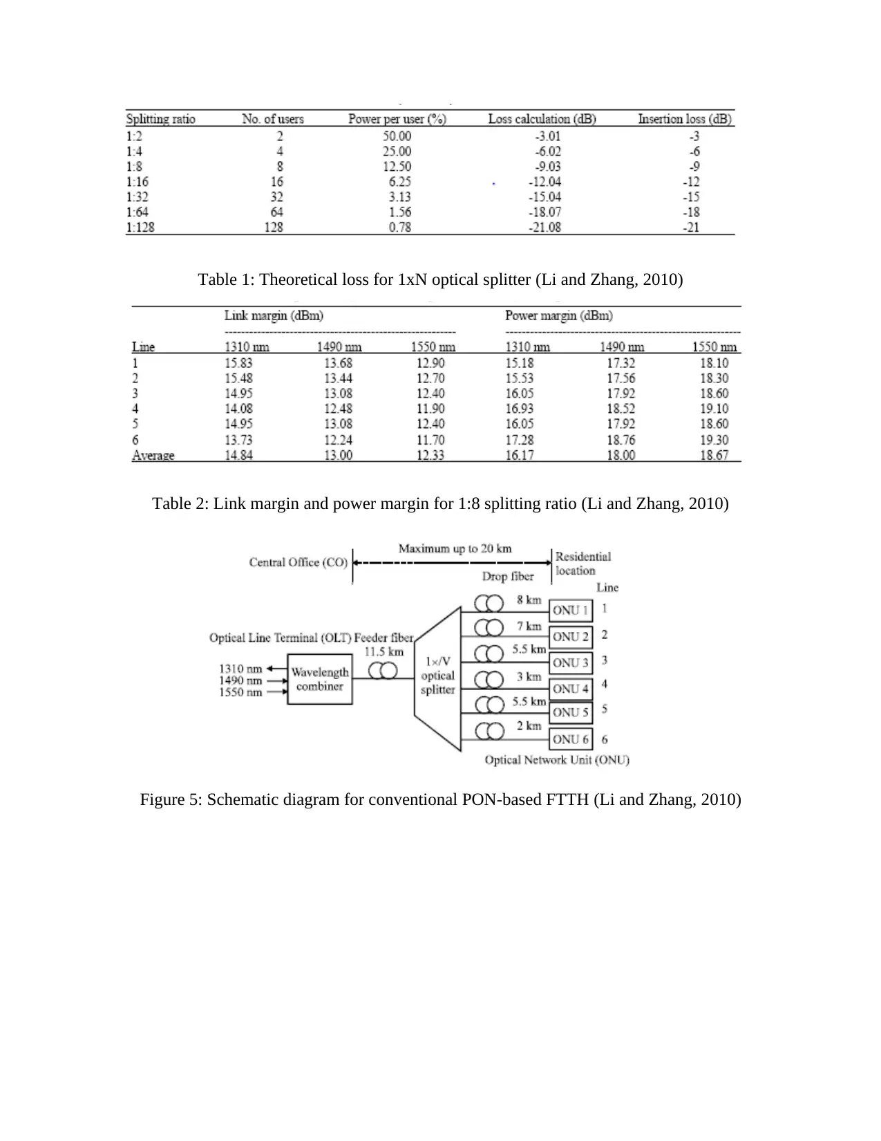
Table 1: Theoretical loss for 1xN optical splitter (Li and Zhang, 2010)
Table 2: Link margin and power margin for 1:8 splitting ratio (Li and Zhang, 2010)
Figure 5: Schematic diagram for conventional PON-based FTTH (Li and Zhang, 2010)
Table 2: Link margin and power margin for 1:8 splitting ratio (Li and Zhang, 2010)
Figure 5: Schematic diagram for conventional PON-based FTTH (Li and Zhang, 2010)
⊘ This is a preview!⊘
Do you want full access?
Subscribe today to unlock all pages.
Trusted by 1+ million students worldwide
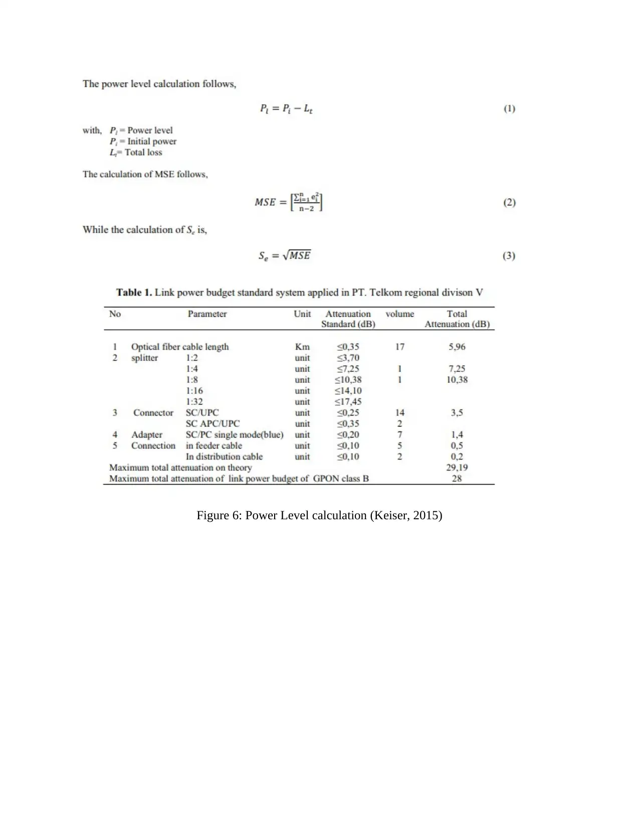
Figure 6: Power Level calculation (Keiser, 2015)
Paraphrase This Document
Need a fresh take? Get an instant paraphrase of this document with our AI Paraphraser
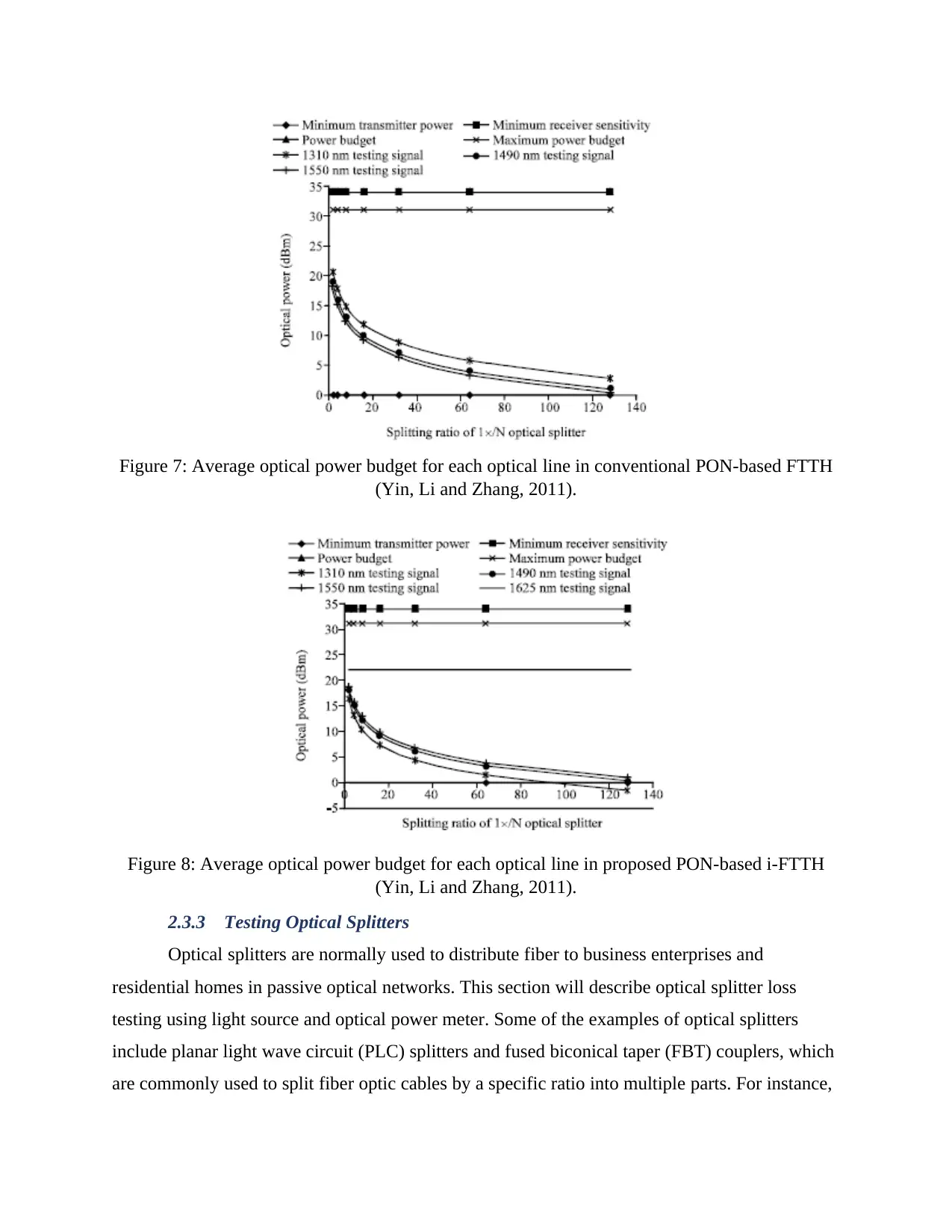
Figure 7: Average optical power budget for each optical line in conventional PON-based FTTH
(Yin, Li and Zhang, 2011).
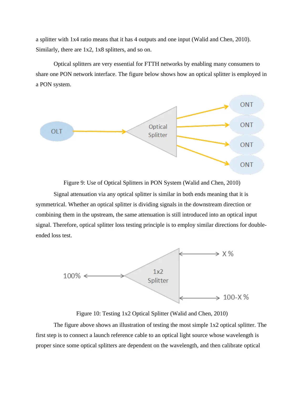
Figure 8: Average optical power budget for each optical line in proposed PON-based i-FTTH
(Yin, Li and Zhang, 2011).
2.3.3 Testing Optical Splitters
Optical splitters are normally used to distribute fiber to business enterprises and
residential homes in passive optical networks. This section will describe optical splitter loss
testing using light source and optical power meter. Some of the examples of optical splitters
include planar light wave circuit (PLC) splitters and fused biconical taper (FBT) couplers, which
are commonly used to split fiber optic cables by a specific ratio into multiple parts. For instance,
(Yin, Li and Zhang, 2011).
Figure 8: Average optical power budget for each optical line in proposed PON-based i-FTTH
(Yin, Li and Zhang, 2011).
2.3.3 Testing Optical Splitters
Optical splitters are normally used to distribute fiber to business enterprises and
residential homes in passive optical networks. This section will describe optical splitter loss
testing using light source and optical power meter. Some of the examples of optical splitters
include planar light wave circuit (PLC) splitters and fused biconical taper (FBT) couplers, which
are commonly used to split fiber optic cables by a specific ratio into multiple parts. For instance,
a splitter with 1x4 ratio means that it has 4 outputs and one input (Walid and Chen, 2010).
Similarly, there are 1x2, 1x8 splitters, and so on.
Optical splitters are very essential for FTTH networks by enabling many consumers to
share one PON network interface. The figure below shows how an optical splitter is employed in
a PON system.
Figure 9: Use of Optical Splitters in PON System (Walid and Chen, 2010)
Signal attenuation via any optical splitter is similar in both ends meaning that it is
symmetrical. Whether an optical splitter is dividing signals in the downstream direction or
combining them in the upstream, the same attenuation is still introduced into an optical input
signal. Therefore, optical splitter loss testing principle is to employ similar directions for double-
ended loss test.
Figure 10: Testing 1x2 Optical Splitter (Walid and Chen, 2010)
The figure above shows an illustration of testing the most simple 1x2 optical splitter. The
first step is to connect a launch reference cable to an optical light source whose wavelength is
proper since some optical splitters are dependent on the wavelength, and then calibrate optical
⊘ This is a preview!⊘
Do you want full access?
Subscribe today to unlock all pages.
Trusted by 1+ million students worldwide
1 out of 60


Your All-in-One AI-Powered Toolkit for Academic Success.
+13062052269
info@desklib.com
Available 24*7 on WhatsApp / Email
![[object Object]](/_next/static/media/star-bottom.7253800d.svg)
Unlock your academic potential
Copyright © 2020–2026 A2Z Services. All Rights Reserved. Developed and managed by ZUCOL.