Aerofoil Design and Performance Analysis: Glider Wing Lift and Drag
VerifiedAdded on 2023/03/21
|6
|1580
|38
Report
AI Summary
This report presents an analysis of aerofoil design, focusing on the generation of lift and the management of drag forces. The study involves wind tunnel experiments to evaluate the performance of different wing designs, including an initial design and an optimized design. The experiments measured lift and drag at various angles of attack to determine the coefficients of lift and drag. The results show that the optimized wing design, with a steeper camber and curved wingtips, generated higher lift and lower drag compared to the initial design. The report discusses the impact of the angle of attack on lift and drag, the role of viscosity, and the importance of wing design in maximizing flight time and performance for gliders. The findings highlight the importance of aerofoil design in enhancing aircraft efficiency and the significance of wind tunnel testing in validating the performance of wing designs.
AIRCRAFT
By Name
Course
Instructor
Institution
Location
Date
By Name
Course
Instructor
Institution
Location
Date
Paraphrase This Document
Need a fresh take? Get an instant paraphrase of this document with our AI Paraphraser
Introduction
An aerofoil defines the wing's cross-sectional shape which generates the aerodynamic forces
upon moving through fluids. Aerofoils may be in nature of wings that produce lift otherwise in
form of propellers which offer thrust. The role of aerofoil that serves as wing of an aircraft is to
offer adequate lift that counters aircraft weight alongside any drag forces that may act on it.
In aircraft, the wing generates lift through the creation of an environment in which pressure
beneath the wing is larger than the pressure that is above. This pressure variation is generated
through having surface of the cambered wing. The camber defines characteristic bend for an
aircraft of the lower or higher part. The cumber plays a major role in the determination of
amount of life that may be generated by the wing. Cambering of the upper surface means the
airflow velocity above is faster than the airflow velocity below resulting in reduced pressure
above the wing surface in comparison to the lower surface pressure thereby resulting in upwards
net lift force. The pressure difference may as well be created through the inclination of the wing
in relation to the airflow direction. Viscosity plays a major aspect of producing lift since it results
in forces of frictional between wing solid part as well as air-fluid resulting in turning of flow.
Operation of wind tunnel
The glider having newly made wings as well as winglets is to be located in wind tunnel for
operation of wind tunnel. Dials were available that would be used in changing the airspeed as
well as the angle of attack at different intervals equipment enabling measurement of both the
analog and digital speeds. Findings for lift and drag were made for every angle of attack with
varied corresponding airspeed digits. Nevertheless, measurements for such values weren’t given
in Newton’s hence had to be changed through given rates of conversion.
Uncertainty and Error Concept
Human error would be the main source of error for glider during the production process of
aerofoil or wing alongside winglets since they would not be accurate as of the ones made as well
as tested in Panuki. It is of importance to make a comparison when taking readings of the data
from analog speed meter to that of digital reader since there may be an error when measurements
are taken by the eyes hence the second measurement may aid in the justification of the actual
speed and in case of any big differences it would be established there is a problem with the
equipment set up. The singular parameter equation U (xi) = ai/k where ai defines system
uncertainty semi-range linked with input while k is advisor linked to assumed probability
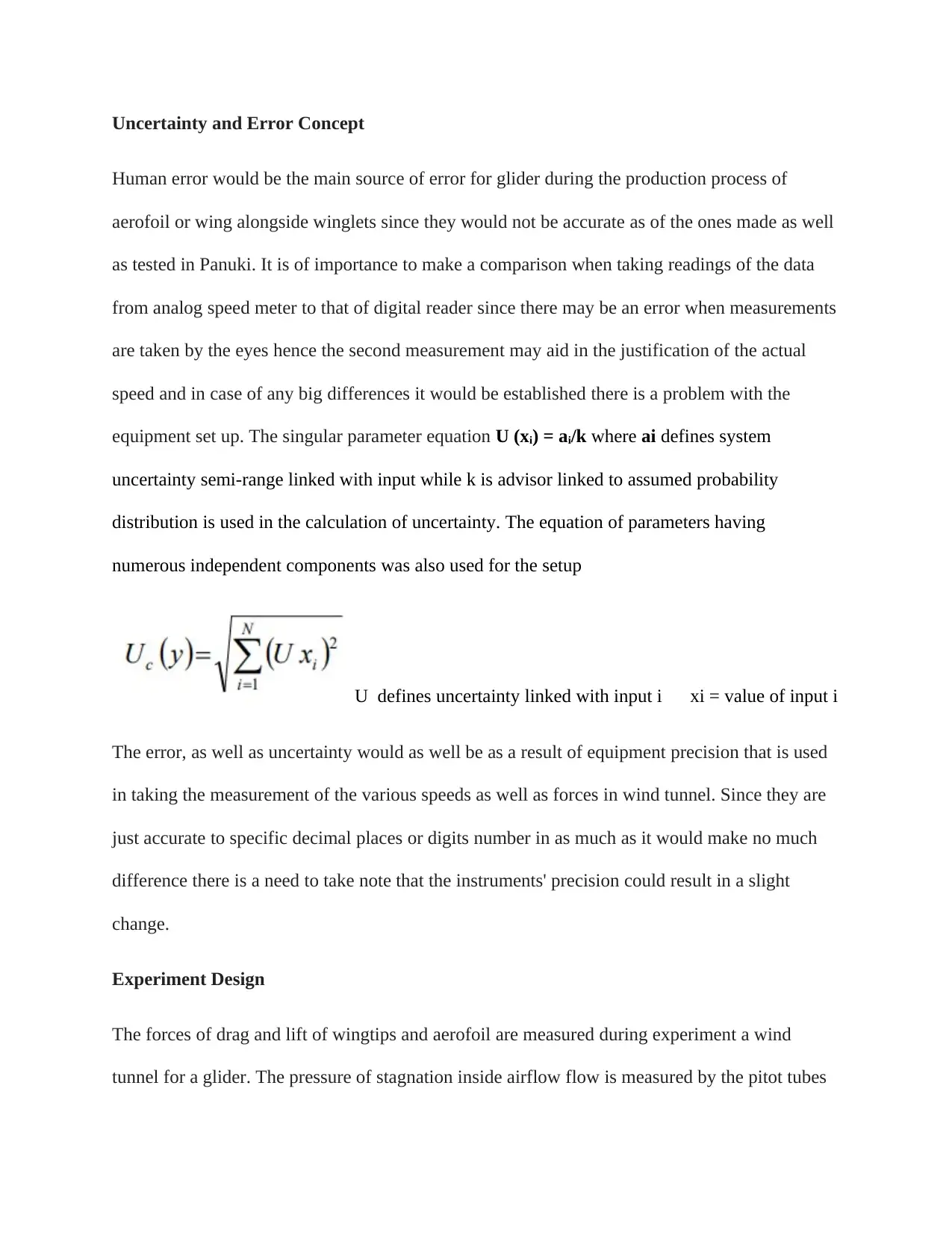
distribution is used in the calculation of uncertainty. The equation of parameters having
numerous independent components was also used for the setup
U defines uncertainty linked with input i xi = value of input i
The error, as well as uncertainty would as well be as a result of equipment precision that is used
in taking the measurement of the various speeds as well as forces in wind tunnel. Since they are
just accurate to specific decimal places or digits number in as much as it would make no much
difference there is a need to take note that the instruments' precision could result in a slight
change.
Experiment Design
The forces of drag and lift of wingtips and aerofoil are measured during experiment a wind
tunnel for a glider. The pressure of stagnation inside airflow flow is measured by the pitot tubes
⊘ This is a preview!⊘
Do you want full access?
Subscribe today to unlock all pages.

Trusted by 1+ million students worldwide
enabling the determination of the drag and glider lift forces. The speeds of fan are set at
relatively low and the greatest speed been placed at 750 RPM to enable reception of any
damages by the glider suppose the tips of wing were not adequately held together or set in place
enabling determination of accurate as well as reliable data on aerofoil despite the errors.
Measurements of the lift as well as drag forces are taken to enable calculation of the lift and drag
coefficients and thereby a comparison made against the optimized wing as well as the Panuki
findings. The measurement of the speed of air is done digitally as well as in analog terms to find
two measurements that would indicate in case there is any challenge with either of instruments of
measuring. Measurement of lift as well as drag forces at various attack angles would enable an
in-depth comprehension of the distribution of pressure besides allowing the plotting of a table to
find out in which region is the highest amount of drag and lift generated by the aerofoil.
Experimental procedure description
The group in which creation of wing which the plane is made of had a rise in lift and a reduction
in the amount of drag for simple wings design for aircraft. The plane had to be put in the wind
tunnel to establish the requirements and thereafter the values of airspeed drag, fan speed, lift read
off at 250, 550 and 750 as well as attack angles. Obtaining attack angles involved a group
member turning the dial to slanted plane. Every degree has value hence attaining the 15 degrees
AoA required turning of the dial 1200 units. Upon obtaining the readings of every of the AoA: 0,
3, 6 as well as 9, units of the lift and drag were 0.025N. The drag and lift are then calculated to
establish most optimal value as well as the point it will match needed specification. The winglet
is changed so there is a drastic increase in the lift and a reduction in the drag to enhance the
plane. The winglet was changed in such a way that it was not vertical in relation to wing but
Paraphrase This Document
Need a fresh take? Get an instant paraphrase of this document with our AI Paraphraser
rather tilted at angle. In doing so in enhanced the lift by amount and lowers drag by the very
amount.
Analysis/ discussion of results
The standard values were set by the initial wing design performance in comparison with the
results of optimized design of wing. The findings derived from wind tunnel demonstrate initial
design showed highest lift at an angle of attack of 9⁰. This demonstrated that of 4 various angles
of attack, largest angle of attack generated highest lift. As there was increase in angle of attack,
there was a corresponding increase in coefficient of lift in a proportional manner. This is owed to
the fact that air beneath the wings is as well deflected downwards at steeper angles resulting in
lift increase. The initial design as well generated highest drag by having wing set at angle of
attack of 9⁰ insinuating angle of attack results in increased drag coefficient in a proportional
manner.
This demonstrated that at some angle wing would start generating drag in opposite direction
since as angle is increased there is a decrease in the speed of air beneath wing and exerting force
on wing to generate drag force. There is an exponential increase in the force since as angle of
attack is enhanced wing tends to be lower aerodynamic meaning there is enhanced surface for
exerting force by air hence resulting in increased drag. By having the lift as high as possible and
the drag as low as possible, an excellent performance needed for glider is attained since this
would ensure the glider is kept at high altitude for a long time hence resulting in increased time
of flight. The lift force has to be larger than drag force in order for flight to glide. There will as
well be need of a light-weight by the glider as it would aid in maintaining the glider flying for
longer in the air. Adoption of first design for glider would not be appropriate since wing does not
generate sufficient lift in comparison with the drag produced meaning the design falls short of
the various efficiencies needed as the flight time would be brief and the glider will be of very
low speed.
From gathered outcomes, it was established optimized wing design worked better in comparison
with the first wing design meaning optimized wing design would be best recommended for glider
application. The angle of attack does not stand out as only factor which may be altered to result
in more lift. Of all designs, optimized wings are the most effective and efficient wing since it
generated more lift in comparison with the drag meaning the glider would have longer time of
flight and may further longer displacements.
Conclusion
The results indicate initial wing is having lower distribution of aerofoil pressure even though
having higher air pressure regions about the vertical tips resulting in enhancement in the
coefficient of drag. This demonstrates less circular wing tip on optimized wing returned higher
efficiency in generation of higher lift as well as lower drag. The optimized wing camber was
steeped and wingtips smaller and curved resulting in higher coefficient as well as lower
coefficient of drag in comparison with first wing.
⊘ This is a preview!⊘
Do you want full access?
Subscribe today to unlock all pages.

Trusted by 1+ million students worldwide
1 out of 6
Your All-in-One AI-Powered Toolkit for Academic Success.
+13062052269
info@desklib.com
Available 24*7 on WhatsApp / Email
![[object Object]](/_next/static/media/star-bottom.7253800d.svg)
Unlock your academic potential
Copyright © 2020–2025 A2Z Services. All Rights Reserved. Developed and managed by ZUCOL.

