ITER Project: Ground Model Assessment and Soil Nailing Analysis Report
VerifiedAdded on 2022/09/01
|17
|3986
|17
Report
AI Summary
This report presents a ground model assessment, specifically focusing on soil embankment and soil nailing to enhance soil structure stability, crucial for haul road support. The analysis utilizes SNAP_2 software to determine nailing placement and soil characteristics, including site conditions and surcharge loading. The design of soil embankments adheres to contractor guidelines, integrating soil nailing to significantly improve soil stability. The report includes an introduction to ground modelling, outlines the scope of the project, and details the assessment of the ground model, critical analysis sections, loading conditions, groundwater and drainage considerations, design codes, and the analysis of the nailed slope. It also provides results, compares them with the contractor's design, and concludes with a reference list and appendices. The report covers various aspects such as the drainage and groundwater system, slope analysis, and design comparisons. The assessment involves site investigation, analysis of geological and technical parameters, and implementation of design instructions. It also discusses critical sections for analysis, including internal, external, and compound reinforced slopes, and the use of Welded Wire Fabric (WWF) for construction. The report further analyzes loading techniques, groundwater and drainage considerations, and design codes such as permissible stress methods.

CIVIL
Paraphrase This Document
Need a fresh take? Get an instant paraphrase of this document with our AI Paraphraser
Executive summary
The report of the ground model is considered based on the soil embankment and soil nailing
features which will help strengthen and increase the stability of the soil structure. Since the
haul road will support the slope, stability plays a crucial role because of the heavy
transportation of weights. In this report, the recommended software for soil nailing and
ground analysis, SNAP_2 has been considered. By using this tool, the nailing and its
placement are also done. The software ultimately gives a brief report regarding the soil
feature, soil nailing, scene of the site, and even the surcharge loading conditions. The design
of the soil embankments has been done considering the contractor’s design guideline of the
soil structure, where the slope is placed with soil nailing. The soil nailing is done to increase
soil stability significantly.
2
Table of Contents
1. Introduction............................................................................................................................4
2. Outline the scope of report.....................................................................................................4
3. Ground model assessment......................................................................................................5
4. Critical sections for analysis..................................................................................................6
5. Loading..................................................................................................................................8
6. Groundwater and drainage.....................................................................................................9
7. Design codes and assessment method..................................................................................10
8. Analysis of nailed slope.......................................................................................................11
9. Results..................................................................................................................................12
10. Comparison with Contractor design...................................................................................12
11. Conclusion..........................................................................................................................13
Reference List..........................................................................................................................14
Appendices...............................................................................................................................16
3
⊘ This is a preview!⊘
Do you want full access?
Subscribe today to unlock all pages.
Trusted by 1+ million students worldwide
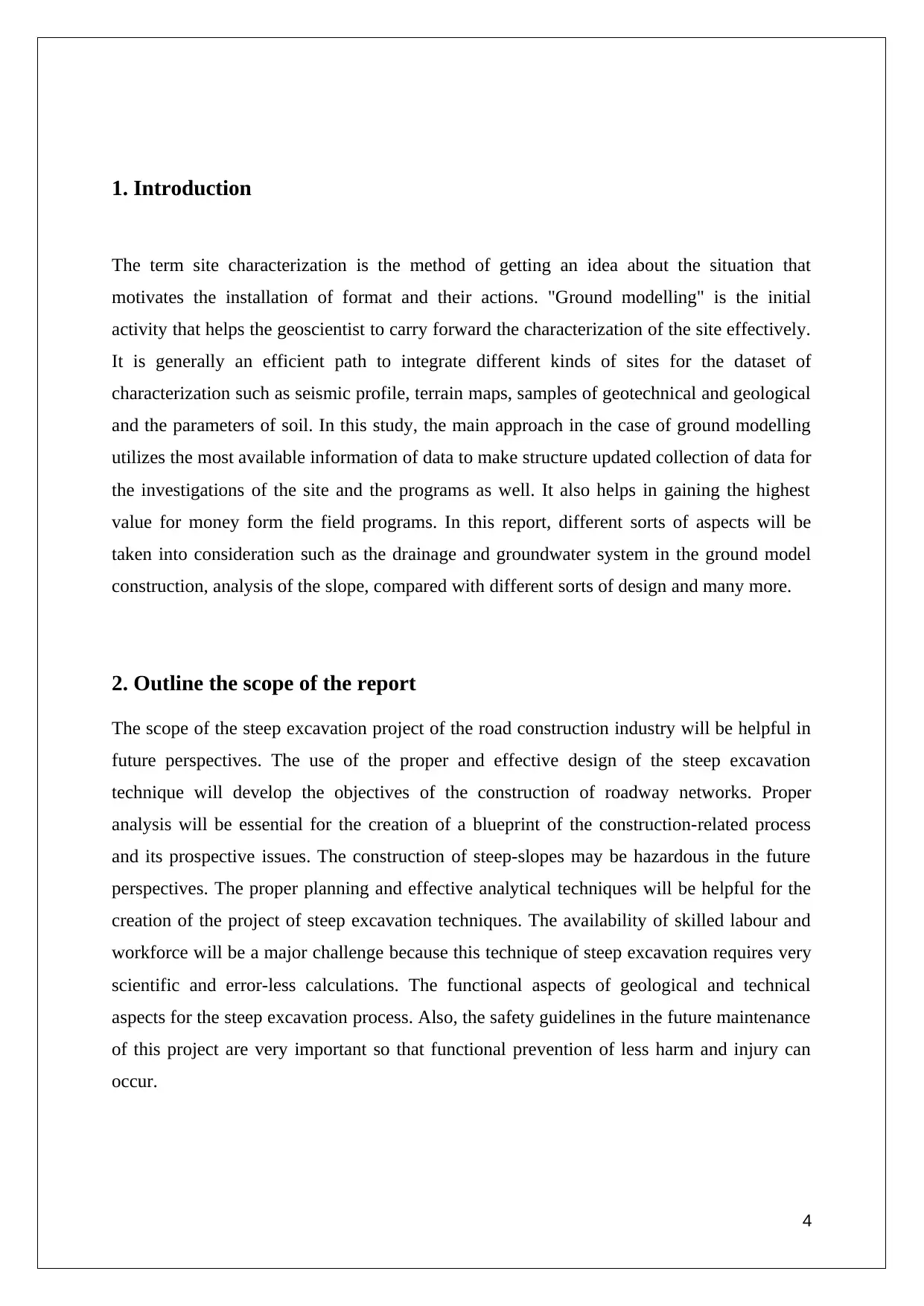
1. Introduction
The term site characterization is the method of getting an idea about the situation that
motivates the installation of format and their actions. "Ground modelling" is the initial
activity that helps the geoscientist to carry forward the characterization of the site effectively.
It is generally an efficient path to integrate different kinds of sites for the dataset of
characterization such as seismic profile, terrain maps, samples of geotechnical and geological
and the parameters of soil. In this study, the main approach in the case of ground modelling
utilizes the most available information of data to make structure updated collection of data for
the investigations of the site and the programs as well. It also helps in gaining the highest
value for money form the field programs. In this report, different sorts of aspects will be
taken into consideration such as the drainage and groundwater system in the ground model
construction, analysis of the slope, compared with different sorts of design and many more.
2. Outline the scope of the report
The scope of the steep excavation project of the road construction industry will be helpful in
future perspectives. The use of the proper and effective design of the steep excavation
technique will develop the objectives of the construction of roadway networks. Proper
analysis will be essential for the creation of a blueprint of the construction-related process
and its prospective issues. The construction of steep-slopes may be hazardous in the future
perspectives. The proper planning and effective analytical techniques will be helpful for the
creation of the project of steep excavation techniques. The availability of skilled labour and
workforce will be a major challenge because this technique of steep excavation requires very
scientific and error-less calculations. The functional aspects of geological and technical
aspects for the steep excavation process. Also, the safety guidelines in the future maintenance
of this project are very important so that functional prevention of less harm and injury can
occur.
4
Paraphrase This Document
Need a fresh take? Get an instant paraphrase of this document with our AI Paraphraser
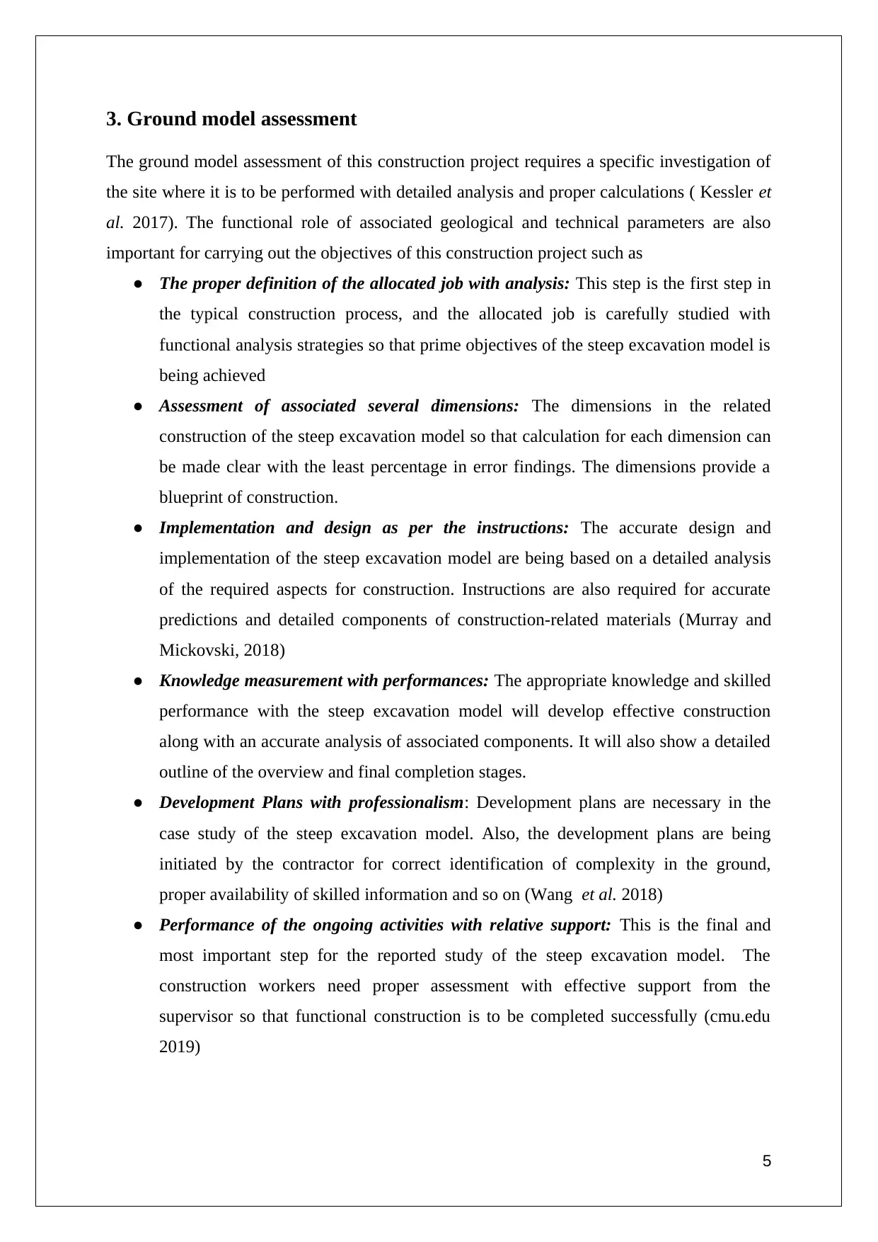
3. Ground model assessment
The ground model assessment of this construction project requires a specific investigation of
the site where it is to be performed with detailed analysis and proper calculations ( Kessler et
al. 2017). The functional role of associated geological and technical parameters are also
important for carrying out the objectives of this construction project such as
● The proper definition of the allocated job with analysis: This step is the first step in
the typical construction process, and the allocated job is carefully studied with
functional analysis strategies so that prime objectives of the steep excavation model is
being achieved
● Assessment of associated several dimensions: The dimensions in the related
construction of the steep excavation model so that calculation for each dimension can
be made clear with the least percentage in error findings. The dimensions provide a
blueprint of construction.
● Implementation and design as per the instructions: The accurate design and
implementation of the steep excavation model are being based on a detailed analysis
of the required aspects for construction. Instructions are also required for accurate
predictions and detailed components of construction-related materials (Murray and
Mickovski, 2018)
● Knowledge measurement with performances: The appropriate knowledge and skilled
performance with the steep excavation model will develop effective construction
along with an accurate analysis of associated components. It will also show a detailed
outline of the overview and final completion stages.
● Development Plans with professionalism: Development plans are necessary in the
case study of the steep excavation model. Also, the development plans are being
initiated by the contractor for correct identification of complexity in the ground,
proper availability of skilled information and so on (Wang et al. 2018)
● Performance of the ongoing activities with relative support: This is the final and
most important step for the reported study of the steep excavation model. The
construction workers need proper assessment with effective support from the
supervisor so that functional construction is to be completed successfully (cmu.edu
2019)
5
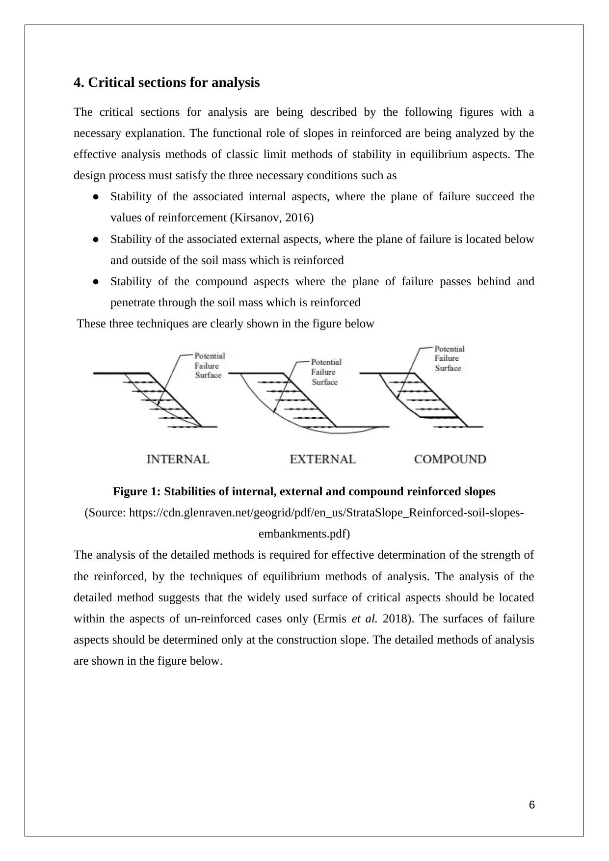
4. Critical sections for analysis
The critical sections for analysis are being described by the following figures with a
necessary explanation. The functional role of slopes in reinforced are being analyzed by the
effective analysis methods of classic limit methods of stability in equilibrium aspects. The
design process must satisfy the three necessary conditions such as
● Stability of the associated internal aspects, where the plane of failure succeed the
values of reinforcement (Kirsanov, 2016)
● Stability of the associated external aspects, where the plane of failure is located below
and outside of the soil mass which is reinforced
● Stability of the compound aspects where the plane of failure passes behind and
penetrate through the soil mass which is reinforced
These three techniques are clearly shown in the figure below
Figure 1: Stabilities of internal, external and compound reinforced slopes
(Source: https://cdn.glenraven.net/geogrid/pdf/en_us/StrataSlope_Reinforced-soil-slopes-
embankments.pdf)
The analysis of the detailed methods is required for effective determination of the strength of
the reinforced, by the techniques of equilibrium methods of analysis. The analysis of the
detailed method suggests that the widely used surface of critical aspects should be located
within the aspects of un-reinforced cases only (Ermis et al. 2018). The surfaces of failure
aspects should be determined only at the construction slope. The detailed methods of analysis
are shown in the figure below.
6
⊘ This is a preview!⊘
Do you want full access?
Subscribe today to unlock all pages.
Trusted by 1+ million students worldwide
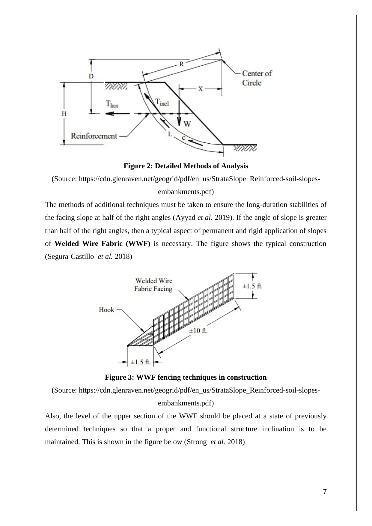
Figure 2: Detailed Methods of Analysis
(Source: https://cdn.glenraven.net/geogrid/pdf/en_us/StrataSlope_Reinforced-soil-slopes-
embankments.pdf)
The methods of additional techniques must be taken to ensure the long-duration stabilities of
the facing slope at half of the right angles (Ayyad et al. 2019). If the angle of slope is greater
than half of the right angles, then a typical aspect of permanent and rigid application of slopes
of Welded Wire Fabric (WWF) is necessary. The figure shows the typical construction
(Segura-Castillo et al. 2018)
Figure 3: WWF fencing techniques in construction
(Source: https://cdn.glenraven.net/geogrid/pdf/en_us/StrataSlope_Reinforced-soil-slopes-
embankments.pdf)
Also, the level of the upper section of the WWF should be placed at a state of previously
determined techniques so that a proper and functional structure inclination is to be
maintained. This is shown in the figure below (Strong et al. 2018)
7
(Source: https://cdn.glenraven.net/geogrid/pdf/en_us/StrataSlope_Reinforced-soil-slopes-
embankments.pdf)
The methods of additional techniques must be taken to ensure the long-duration stabilities of
the facing slope at half of the right angles (Ayyad et al. 2019). If the angle of slope is greater
than half of the right angles, then a typical aspect of permanent and rigid application of slopes
of Welded Wire Fabric (WWF) is necessary. The figure shows the typical construction
(Segura-Castillo et al. 2018)
Figure 3: WWF fencing techniques in construction
(Source: https://cdn.glenraven.net/geogrid/pdf/en_us/StrataSlope_Reinforced-soil-slopes-
embankments.pdf)
Also, the level of the upper section of the WWF should be placed at a state of previously
determined techniques so that a proper and functional structure inclination is to be
maintained. This is shown in the figure below (Strong et al. 2018)
7
Paraphrase This Document
Need a fresh take? Get an instant paraphrase of this document with our AI Paraphraser
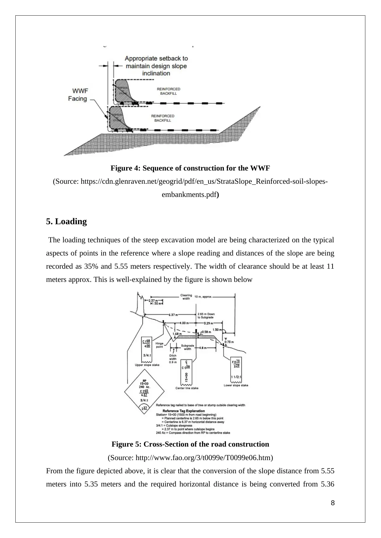
Figure 4: Sequence of construction for the WWF
(Source: https://cdn.glenraven.net/geogrid/pdf/en_us/StrataSlope_Reinforced-soil-slopes-
embankments.pdf)
5. Loading
The loading techniques of the steep excavation model are being characterized on the typical
aspects of points in the reference where a slope reading and distances of the slope are being
recorded as 35% and 5.55 meters respectively. The width of clearance should be at least 11
meters approx. This is well-explained by the figure is shown below
Figure 5: Cross-Section of the road construction
(Source: http://www.fao.org/3/t0099e/T0099e06.htm)
From the figure depicted above, it is clear that the conversion of the slope distance from 5.55
meters into 5.35 meters and the required horizontal distance is being converted from 5.36
8
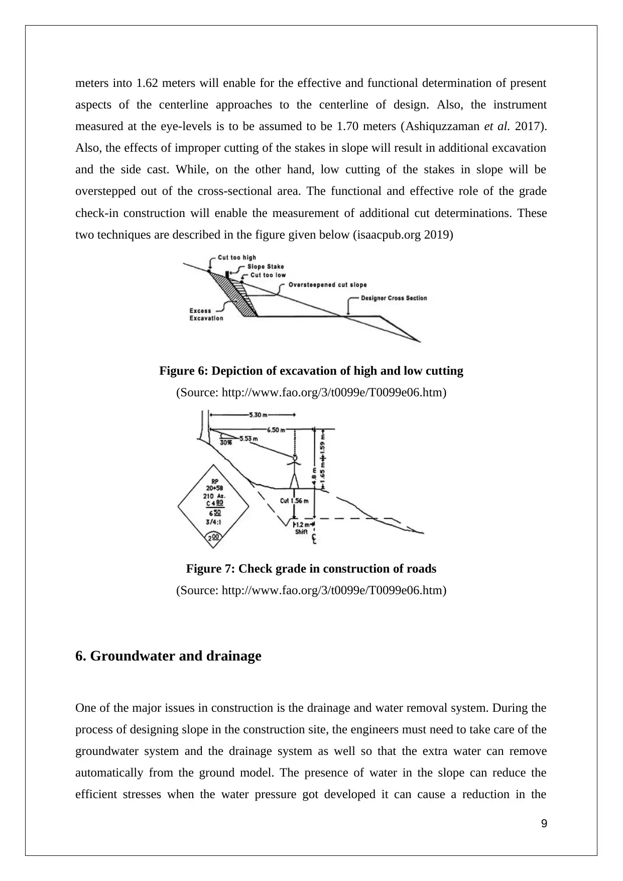
meters into 1.62 meters will enable for the effective and functional determination of present
aspects of the centerline approaches to the centerline of design. Also, the instrument
measured at the eye-levels is to be assumed to be 1.70 meters (Ashiquzzaman et al. 2017).
Also, the effects of improper cutting of the stakes in slope will result in additional excavation
and the side cast. While, on the other hand, low cutting of the stakes in slope will be
overstepped out of the cross-sectional area. The functional and effective role of the grade
check-in construction will enable the measurement of additional cut determinations. These
two techniques are described in the figure given below (isaacpub.org 2019)
Figure 6: Depiction of excavation of high and low cutting
(Source: http://www.fao.org/3/t0099e/T0099e06.htm)
Figure 7: Check grade in construction of roads
(Source: http://www.fao.org/3/t0099e/T0099e06.htm)
6. Groundwater and drainage
One of the major issues in construction is the drainage and water removal system. During the
process of designing slope in the construction site, the engineers must need to take care of the
groundwater system and the drainage system as well so that the extra water can remove
automatically from the ground model. The presence of water in the slope can reduce the
efficient stresses when the water pressure got developed it can cause a reduction in the
9
⊘ This is a preview!⊘
Do you want full access?
Subscribe today to unlock all pages.
Trusted by 1+ million students worldwide
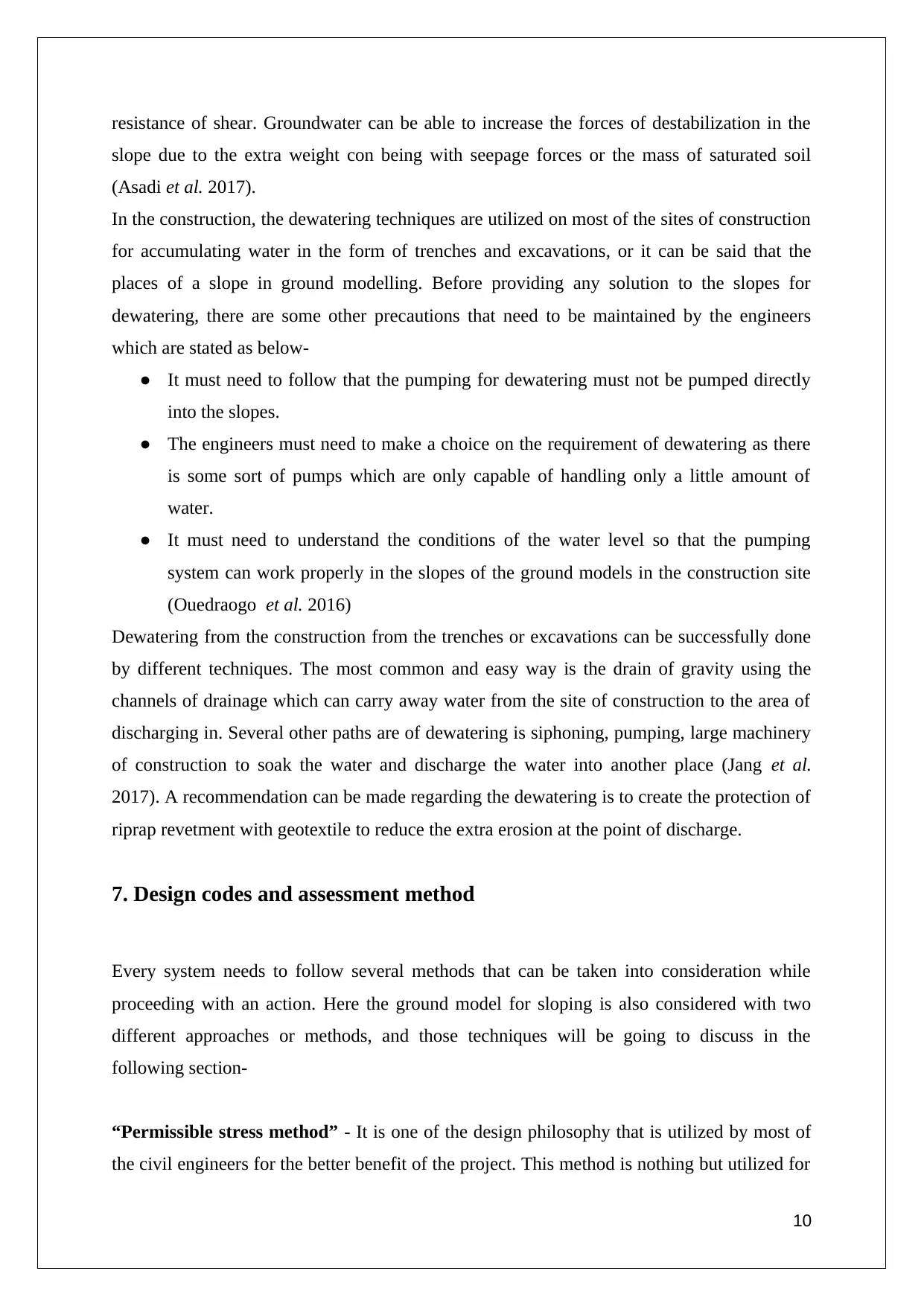
resistance of shear. Groundwater can be able to increase the forces of destabilization in the
slope due to the extra weight con being with seepage forces or the mass of saturated soil
(Asadi et al. 2017).
In the construction, the dewatering techniques are utilized on most of the sites of construction
for accumulating water in the form of trenches and excavations, or it can be said that the
places of a slope in ground modelling. Before providing any solution to the slopes for
dewatering, there are some other precautions that need to be maintained by the engineers
which are stated as below-
● It must need to follow that the pumping for dewatering must not be pumped directly
into the slopes.
● The engineers must need to make a choice on the requirement of dewatering as there
is some sort of pumps which are only capable of handling only a little amount of
water.
● It must need to understand the conditions of the water level so that the pumping
system can work properly in the slopes of the ground models in the construction site
(Ouedraogo et al. 2016)
Dewatering from the construction from the trenches or excavations can be successfully done
by different techniques. The most common and easy way is the drain of gravity using the
channels of drainage which can carry away water from the site of construction to the area of
discharging in. Several other paths are of dewatering is siphoning, pumping, large machinery
of construction to soak the water and discharge the water into another place (Jang et al.
2017). A recommendation can be made regarding the dewatering is to create the protection of
riprap revetment with geotextile to reduce the extra erosion at the point of discharge.
7. Design codes and assessment method
Every system needs to follow several methods that can be taken into consideration while
proceeding with an action. Here the ground model for sloping is also considered with two
different approaches or methods, and those techniques will be going to discuss in the
following section-
“Permissible stress method” - It is one of the design philosophy that is utilized by most of
the civil engineers for the better benefit of the project. This method is nothing but utilized for
10
Paraphrase This Document
Need a fresh take? Get an instant paraphrase of this document with our AI Paraphraser
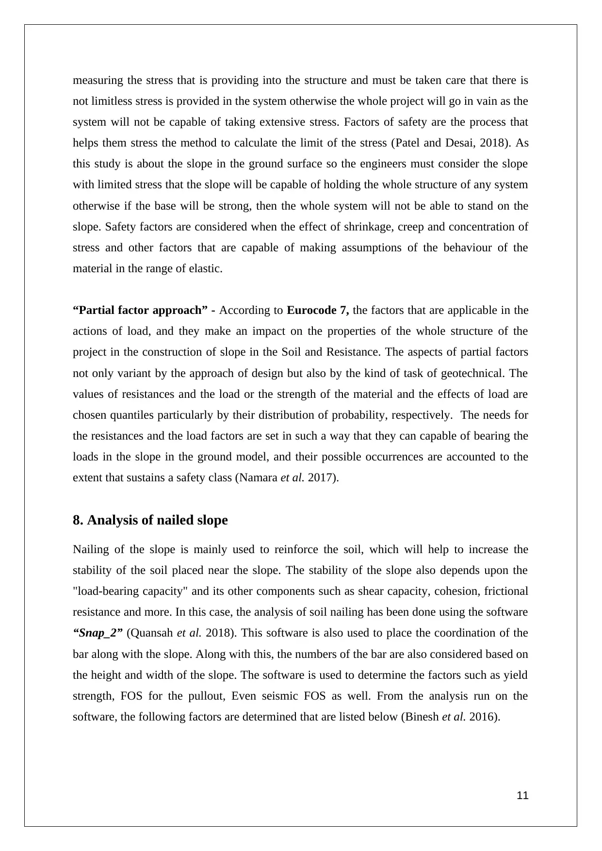
measuring the stress that is providing into the structure and must be taken care that there is
not limitless stress is provided in the system otherwise the whole project will go in vain as the
system will not be capable of taking extensive stress. Factors of safety are the process that
helps them stress the method to calculate the limit of the stress (Patel and Desai, 2018). As
this study is about the slope in the ground surface so the engineers must consider the slope
with limited stress that the slope will be capable of holding the whole structure of any system
otherwise if the base will be strong, then the whole system will not be able to stand on the
slope. Safety factors are considered when the effect of shrinkage, creep and concentration of
stress and other factors that are capable of making assumptions of the behaviour of the
material in the range of elastic.
“Partial factor approach” - According to Eurocode 7, the factors that are applicable in the
actions of load, and they make an impact on the properties of the whole structure of the
project in the construction of slope in the Soil and Resistance. The aspects of partial factors
not only variant by the approach of design but also by the kind of task of geotechnical. The
values of resistances and the load or the strength of the material and the effects of load are
chosen quantiles particularly by their distribution of probability, respectively. The needs for
the resistances and the load factors are set in such a way that they can capable of bearing the
loads in the slope in the ground model, and their possible occurrences are accounted to the
extent that sustains a safety class (Namara et al. 2017).
8. Analysis of nailed slope
Nailing of the slope is mainly used to reinforce the soil, which will help to increase the
stability of the soil placed near the slope. The stability of the slope also depends upon the
"load-bearing capacity" and its other components such as shear capacity, cohesion, frictional
resistance and more. In this case, the analysis of soil nailing has been done using the software
“Snap_2” (Quansah et al. 2018). This software is also used to place the coordination of the
bar along with the slope. Along with this, the numbers of the bar are also considered based on
the height and width of the slope. The software is used to determine the factors such as yield
strength, FOS for the pullout, Even seismic FOS as well. From the analysis run on the
software, the following factors are determined that are listed below (Binesh et al. 2016).
11
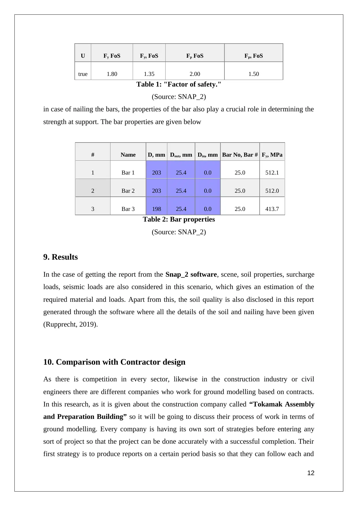
U Fy FoS Fys FoS Fp FoS Fps FoS
true 1.80 1.35 2.00 1.50
Table 1: "Factor of safety."
(Source: SNAP_2)
in case of nailing the bars, the properties of the bar also play a crucial role in determining the
strength at support. The bar properties are given below
# Name D, mm Dout, mm Din, mm Bar No, Bar # Fy, MPa
1 Bar 1 203 25.4 0.0 25.0 512.1
2 Bar 2 203 25.4 0.0 25.0 512.0
3 Bar 3 198 25.4 0.0 25.0 413.7
Table 2: Bar properties
(Source: SNAP_2)
9. Results
In the case of getting the report from the Snap_2 software, scene, soil properties, surcharge
loads, seismic loads are also considered in this scenario, which gives an estimation of the
required material and loads. Apart from this, the soil quality is also disclosed in this report
generated through the software where all the details of the soil and nailing have been given
(Rupprecht, 2019).
10. Comparison with Contractor design
As there is competition in every sector, likewise in the construction industry or civil
engineers there are different companies who work for ground modelling based on contracts.
In this research, as it is given about the construction company called “Tokamak Assembly
and Preparation Building” so it will be going to discuss their process of work in terms of
ground modelling. Every company is having its own sort of strategies before entering any
sort of project so that the project can be done accurately with a successful completion. Their
first strategy is to produce reports on a certain period basis so that they can follow each and
12
⊘ This is a preview!⊘
Do you want full access?
Subscribe today to unlock all pages.
Trusted by 1+ million students worldwide
1 out of 17
Related Documents


Your All-in-One AI-Powered Toolkit for Academic Success.
+13062052269
info@desklib.com
Available 24*7 on WhatsApp / Email
![[object Object]](/_next/static/media/star-bottom.7253800d.svg)
Unlock your academic potential
Copyright © 2020–2026 A2Z Services. All Rights Reserved. Developed and managed by ZUCOL.