Evaluating Vertical GSHP Performance in Saudi Arabia's Climate
VerifiedAdded on 2023/06/10
|43
|10088
|189
Thesis and Dissertation
AI Summary
This thesis examines the performance of vertical Ground Source Heat Pumps (GSHPs) in the hot and dry climate of Saudi Arabia, aiming to reduce costs, CO2 emissions, and save energy. The study critically reviews existing GSHP technology, presents the concept of GSHP thermal performance, and investigates operational temperatures and heat transfer effects. It analyzes soil heat accumulation in high-temperature regions, estimates total energy savings across a forecast period, and assesses the potential energy savings and peak demand reductions using GHSP systems. The research methodology employs mathematical and numerical analyses, utilizing Ground Loop Design (GLD) programs and TRNSYS simulation software to investigate the impact of weather, soil, and load parameters on GSHP performance, including the vertical separation distance between ground loop pipes under Saudi Arabia's geographical conditions. The study also includes a literature review of energy use history, renewable energy trends, geothermal energy, and the application of ground source heat pumps in similar climates.
Contribute Materials
Your contribution can guide someone’s learning journey. Share your
documents today.

The Performance of Vertical Ground Source Heat Pumps (GSHPs) in Hot/Dry Climates (Saudi
Arabia)
By:
Faisal Alshehri
The University of Sheffield
Faculty of Engineering
Department of Mechanical Engineering
Arabia)
By:
Faisal Alshehri
The University of Sheffield
Faculty of Engineering
Department of Mechanical Engineering
Secure Best Marks with AI Grader
Need help grading? Try our AI Grader for instant feedback on your assignments.

Submission Date
10 Jul. 2018
Table of content
Chapter 1 Introduction
1.1 Research background………………………………………… 1
1.2 Saudi Arabia vision 2030……………………………………. 2
1.3 Thesis aims and objectives……………………………………. 3
1.4 Methodology…………………………………………………. 4
Chapter 2 Literature Review
2.1 History of energy use…………………………………………. 5
2.2 Renewable energy……………………………………………. 6
2.3 Renewable energy trend ……………………………………. 7
2.4 Geothermal energy …………………………………………… 9
2.5 History of the heat pump……………………………………… 10
2.5.1 Heat pump and refrigerators………………………. 11
2.5.2 Heat pump components……………………………. 12
2.5.3 Basic heat pump cycle………………………………. 14
2.6 Ground source heat pump technology…………..……….… 16
2.7 Principle of operation of GSHPs……………………………… 17
2.7.1 Ground loop………………………………………... 17`
2.7.2 Heat pump…………………………………………... 18
2.7.3 Distribution system…………………………………. 18
2.8 Factors affecting GSHP operations…………………………. 19
2.9 Types of geothermal heat pump systems…………………… 20
2.9.1 Closed loop system…………………………………. 20
2.9.1.1 Vertical closed loop………………………. 21
2.9.1.2 Horizontal closed loop……………………. 21

2.9.1.3 Slinky closed loop………………………… 23
2.9.1.4 Closed pond loop…………………………. 23
2.9.2 Open loop systems…………………………………. 23
2.10 Ground source heat pumps in hot and dry climates ………… 25
2.10.1 Saudi Arabia ………………………………………. 25
2.10.2 Erbil, Iraq…………………………………………. 26
2.10.3 Tunisia ……………………………………………. 27
2.10.4 Qatar………………………………………………. 28
2.10.5 Egypt ……………………………………………… 28
2.10.6 Algerian……………………………………………. 29
2.11 Conclusion…………………………………………………... 30

Chapter 1 Introduction
1.1 Research Background
Saudi Arabia, officially known as the Kingdom of Saudi Arabia, is a nation-state in the Arab
sovereign and is situated in Western Asia. It has a land mass of approximately 2,150,000 km2
and a population of 32.5 million (General Authority for Statistics, 2018). It has a hot temperature
and becomes very warm during the summer, except for the mountains in the south-western
region. Also, monsoon is very rare in this country and occurs only in a few months (Sultana and
Nasrollahi, 2018). However, it is particularly mild in the winter, with the aforementioned
exception of the south-western region. Most of the climatic features are due to the desert
conditions that are predominately present in the Kingdom.
In terms of energy consumption, energy supplies in Saudi Arabia totally depend on oil and gas
power plants. In Saudi Arabia, energy consumption is extensively subsidized leading to overuse
and misallocation of oil and natural gas resources. The subsidization of energy has given little
incentive for its fast-growing population to save energy consumption in the different economic
activities (Alshehry and Belloumi, 2015). For this reason, domestic energy consumption of oil
has rapidly grown in the past 40-year period and has recently comprised one-fourth of the total
oil production in the country. Over the last five years, Saudi Arabia’s domestic energy
consumption has rapidly grown by 10% annually, with an average of 6% over the last three
decades. The 3.4% population growth per year has had a large impact on the consumption of
domestic oil. This has led to a rapid increase in the demand of electricity in the country. In
addition, it has been estimated that by the year 2025 the electricity generation of Saudi Arabia
might become more than double of the existing demand (Ramli et al., 2015). This is due to the
1
Secure Best Marks with AI Grader
Need help grading? Try our AI Grader for instant feedback on your assignments.

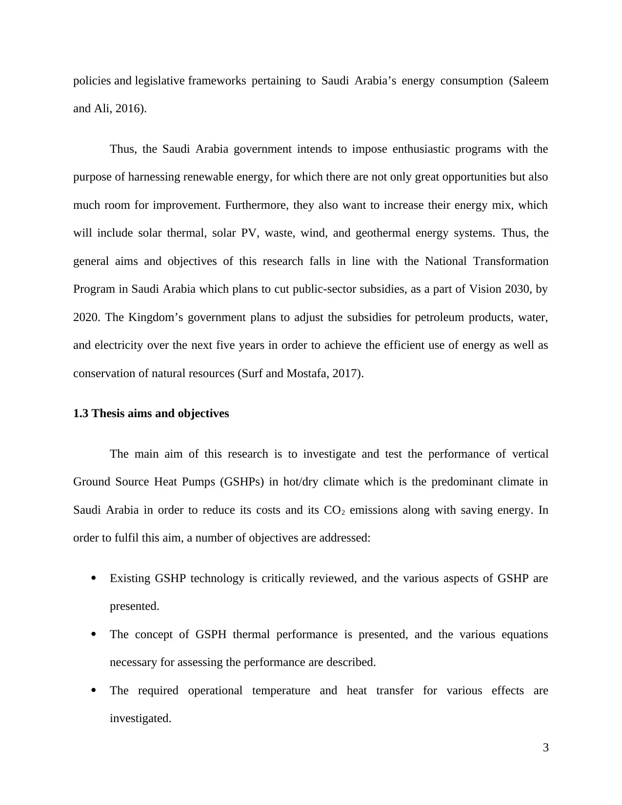
projected growth in the population and the current energy demands. Moreover, Saudi Arabia has
benefitted by the high level of energy consumption per capita, making it one of the predominant
global polluters (in terms of the energy used per capita). This has resulted in 16 metric tons of
carbon dioxide emissions per capita in the year 2009, in comparison to a global average of about
4.7 metric tons. Therefore, the government of Saudi Arabia is attempting to reduce their
greenhouse gas emissions by 130 metric tons (Mt CO2), preferably by 2030.
In addition, research has projected that the peak demand for electricity will reach 70% in 2030
(Al-Yousef and Al-Sheikh, 2012) and 70% of the consumption of the electrical energy per
building will be consumed by ventilation, heating, and air conditioning purposes (HVAC). For
example, in 2010, due to the high temperatures during the summer and an outdoor temperature
of 45 C, buildings consume 65% of the total electricity the and this is 47% higher than the
world average. Hence, special focus should be given to air conditioning systems. This can be
achieved by setting higher efficiency standards, implementing adequate insulation measures as
well as using renewable energy.
1.2 Saudi Arabia Vision 2030
One of the main goals of the Saudi Arabia Vision 2030 is to transform the Kingdom’s oil-
dependent economy to one which is diverse, sustainable, and situated at the crossroads of
international trade. A significant target under the Vision 2030 is to decrease the energy
consumption and greenhouse gas emissions from both the building and industrial sectors. Thus,
the Saudi Arabia Renewable Energy program started with establishment of the King Abdullah
City for Atomic and Renewable Energy (KACARE) which is responsible for the development of
technology which relates to renewable energy, associated research, and the setting of the
2

policies and legislative frameworks pertaining to Saudi Arabia’s energy consumption (Saleem
and Ali, 2016).
Thus, the Saudi Arabia government intends to impose enthusiastic programs with the
purpose of harnessing renewable energy, for which there are not only great opportunities but also
much room for improvement. Furthermore, they also want to increase their energy mix, which
will include solar thermal, solar PV, waste, wind, and geothermal energy systems. Thus, the
general aims and objectives of this research falls in line with the National Transformation
Program in Saudi Arabia which plans to cut public-sector subsidies, as a part of Vision 2030, by
2020. The Kingdom’s government plans to adjust the subsidies for petroleum products, water,
and electricity over the next five years in order to achieve the efficient use of energy as well as
conservation of natural resources (Surf and Mostafa, 2017).
1.3 Thesis aims and objectives
The main aim of this research is to investigate and test the performance of vertical
Ground Source Heat Pumps (GSHPs) in hot/dry climate which is the predominant climate in
Saudi Arabia in order to reduce its costs and its CO2 emissions along with saving energy. In
order to fulfil this aim, a number of objectives are addressed:
Existing GSHP technology is critically reviewed, and the various aspects of GSHP are
presented.
The concept of GSPH thermal performance is presented, and the various equations
necessary for assessing the performance are described.
The required operational temperature and heat transfer for various effects are
investigated.
3

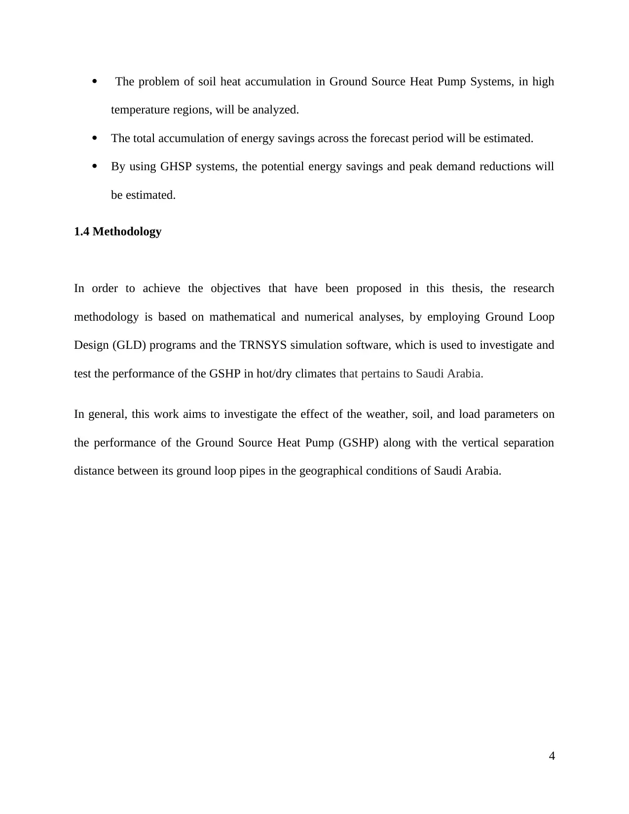
The problem of soil heat accumulation in Ground Source Heat Pump Systems, in high
temperature regions, will be analyzed.
The total accumulation of energy savings across the forecast period will be estimated.
By using GHSP systems, the potential energy savings and peak demand reductions will
be estimated.
1.4 Methodology
In order to achieve the objectives that have been proposed in this thesis, the research
methodology is based on mathematical and numerical analyses, by employing Ground Loop
Design (GLD) programs and the TRNSYS simulation software, which is used to investigate and
test the performance of the GSHP in hot/dry climates that pertains to Saudi Arabia.
In general, this work aims to investigate the effect of the weather, soil, and load parameters on
the performance of the Ground Source Heat Pump (GSHP) along with the vertical separation
distance between its ground loop pipes in the geographical conditions of Saudi Arabia.
4
Paraphrase This Document
Need a fresh take? Get an instant paraphrase of this document with our AI Paraphraser

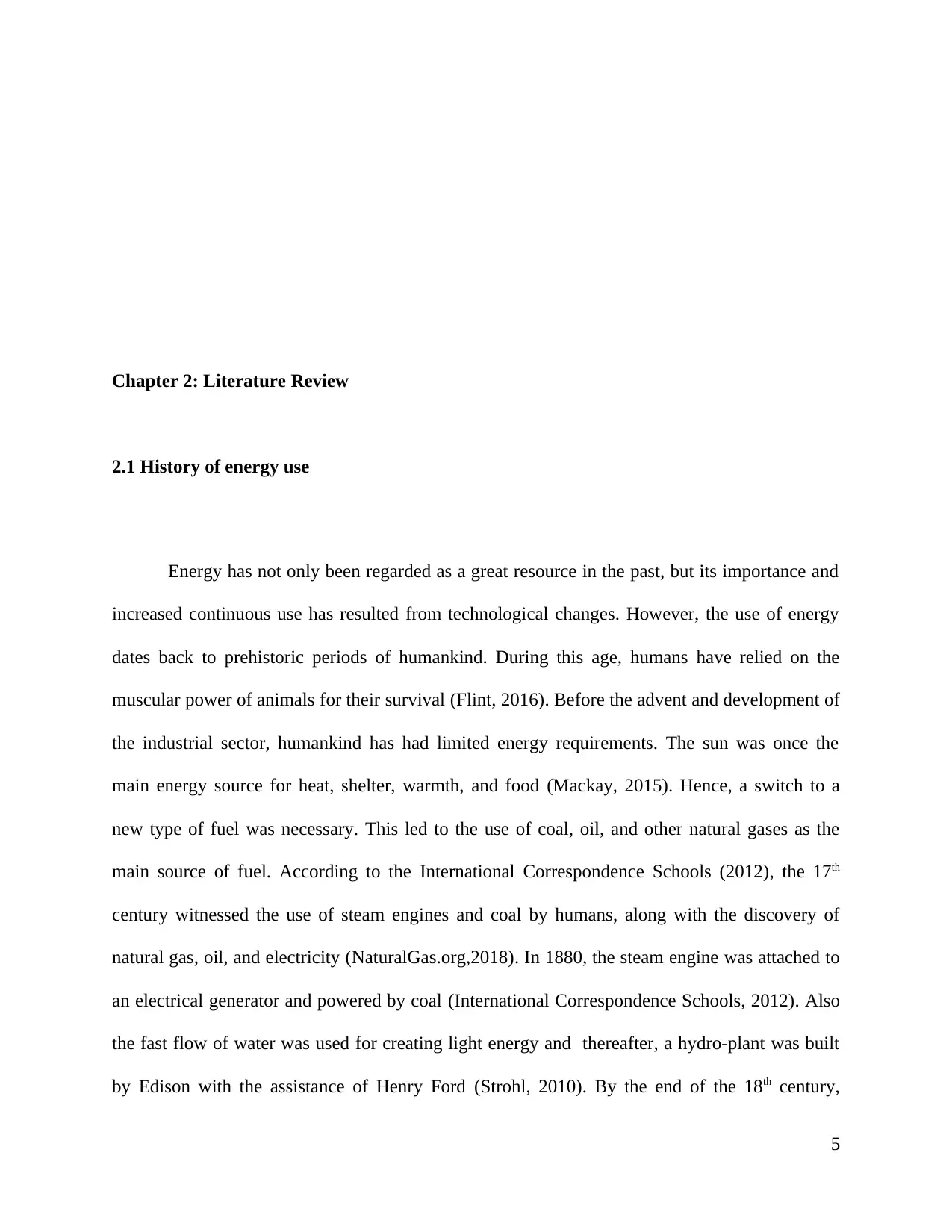
Chapter 2: Literature Review
2.1 History of energy use
Energy has not only been regarded as a great resource in the past, but its importance and
increased continuous use has resulted from technological changes. However, the use of energy
dates back to prehistoric periods of humankind. During this age, humans have relied on the
muscular power of animals for their survival (Flint, 2016). Before the advent and development of
the industrial sector, humankind has had limited energy requirements. The sun was once the
main energy source for heat, shelter, warmth, and food (Mackay, 2015). Hence, a switch to a
new type of fuel was necessary. This led to the use of coal, oil, and other natural gases as the
main source of fuel. According to the International Correspondence Schools (2012), the 17th
century witnessed the use of steam engines and coal by humans, along with the discovery of
natural gas, oil, and electricity (NaturalGas.org,2018). In 1880, the steam engine was attached to
an electrical generator and powered by coal (International Correspondence Schools, 2012). Also
the fast flow of water was used for creating light energy and thereafter, a hydro-plant was built
by Edison with the assistance of Henry Ford (Strohl, 2010). By the end of the 18th century,
5

petroleum, along with gasoline, was being used as fuel to fire the combustion engines which
were slowly being developed (Boyle & Open University, 2012).
Because of the rapid development and invention of several energy sources and technologies, the
17th and 18th centuries have often been considered as the starting point of the Industrial
Revolution (Pierce, 2005). The world’s human population and their energy usage saw a
significant growth during this period. To achieve the increasing energy requirements worldwide,
the world’s energy production increased rapidly. This energy demand was supported by the
larger power plants as well as hydro plants. A large variety of energy sources were being sought
to generate more power and electricity was made available even in rural regions (Hinrichs &
Kleinbach, 2013).
New technologies have been developed in the modern age. Due to the extensive use of natural
gas, petroleum, and other fossil fuels that have been used to support the high energy demand,
there was a great decline in the availability of these non-renewable fossil fuels. This called for
the invention of new technologies and alternative sources of energy in order to generate the
requisite amount of power. In the 19th century, nuclear power started to be used (Cumo, 2017). In
the 20th century can be regarded as the modern era with regard to energy usage, consumption,
and technological developments. The development and advancement in the field of computers,
IT sectors, space exploration, etc. have provided ample support towards exploring new energy
sources in the modern era. Along with fossil fuels and petroleum, renewable energy sources have
also been used to produce the required amount of energy (Shere, 2013). At present, the use of
renewable energy sources has been large-scale. Nowadays, many countries are quite dependent
on solar and wind energy while eschewing their dependence on conventional sources of energy
(Boyle & Open University, 2012). Along with harnessing wind and solar energy, developed
6

countries have increased the funding of research activities aimed at identifying and harnessing
different sources of energy including biomass, hydraulic, solar, wind, geothermal, wave, tidal,
biogas, ocean, fuel cells, and hydrogen, in order to improve the ways of harnessing energy from
sources and support a clean environment with no gaseous emissions (Sierra Forest Legacy,
2012).
2.2 Renewable energy
In 1973, the oil crisis in many countries made them think about alternatives to oil and they
started looking for sources of renewable energy. Actually, there are numerous different sources
and forms of energy. Broadly, there are two sources: renewable and non-renewable energy
(Bartoletto, 2012). However, there is a slight difference between the two sources of energy;
renewable energy is obtained from sources at a less, or equal, rate in which the source
replenishes itself. In other words, it is derived from sources which will never be completely
depleted and will continue to provide energy for many years to come. Examples of renewable
energy include, but are not limited to, solar, wind, geothermal, biomass, ocean waves, and
hydraulic energy. On the other hand, non-renewable energy sources are obtained at a rate which
exceeds the rate at which the sources replenish themselves, e.g. uranium (which is used for
nuclear fusion) and fossil fuels (Harold et al., 1963; Wang & Chen, 2016).
2.3 Renewable Energy Trend
Over the last few decades, excessive use of fossil fuels has resulted in an increase in
carbon dioxide emissions. Due to the massive use of oil and the high demand for energy,
developed and developing countries are seeking to apply advanced technological innovations
that meet the requirements of safe and efficient energy and do not adversely affect the climate
7
Secure Best Marks with AI Grader
Need help grading? Try our AI Grader for instant feedback on your assignments.

(Bartoletto, 2012; Malanima, 2006). Although technological innovation is a key driver of energy
transition, there are many other related factors which include, but are not limited to, politics,
culture, economy, and geography. These considerations are important when selecting distinct
technologies which are to be adopted in the course of harnessing energy sources as well as
providing other energy-related services worldwide (Cottrell, 2009). Also, developed countries
have increased the funds allotted towards research activities regarding different sources of
renewable energy, in order to support a clean environment with no emissions (Sierra Forest
Legacy2012)
According to the renewable global status report (REN21, 2017) the increase in the
demand of renewable energy has taken place in several directions and can be summarized
as follows:
(i) .Growth: In 2015, the use of renewable energy amounted to about 19.3% of the global
energy consumption.
(ii) . Energy Policy: 176 countries had renewable energy targets, 126 countries had power
policies, 68 countries had transport policies, and 21 countries had heating and cooling
policies.
(iii) .Job Opportunity: In 2016, the renewable energy industry employed around 9.8
million to their workforce, which was 1.1% higher than their employment percentile
in 2015.
(iv). Investment: The market share of renewable energy was 241.6 billion USD in 2016.
For the past five years, the investment in the sector of renewable power energy has
been almost double of what has been invested in harnessing the energy based on
fossil fuels.
8

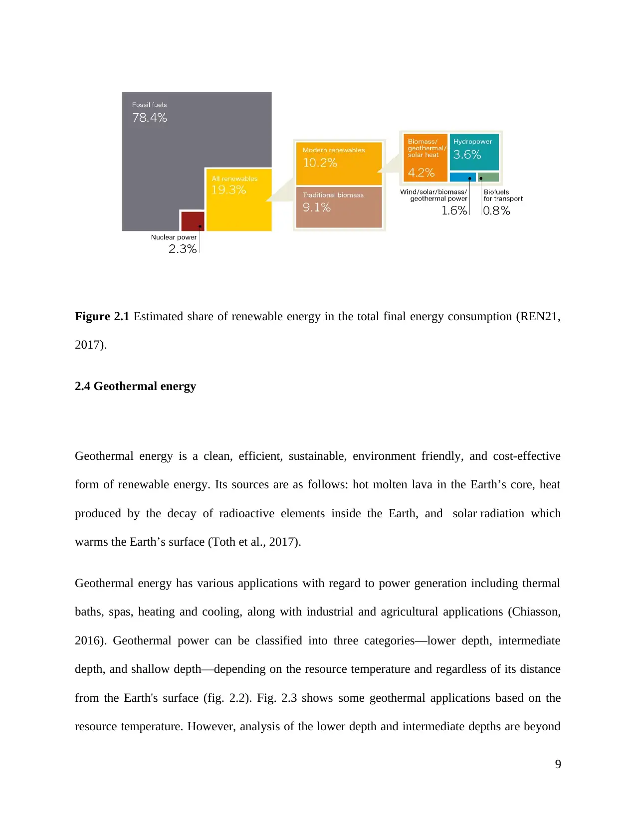
Figure 2.1 Estimated share of renewable energy in the total final energy consumption (REN21,
2017).
2.4 Geothermal energy
Geothermal energy is a clean, efficient, sustainable, environment friendly, and cost-effective
form of renewable energy. Its sources are as follows: hot molten lava in the Earth’s core, heat
produced by the decay of radioactive elements inside the Earth, and solar radiation which
warms the Earth’s surface (Toth et al., 2017).
Geothermal energy has various applications with regard to power generation including thermal
baths, spas, heating and cooling, along with industrial and agricultural applications (Chiasson,
2016). Geothermal power can be classified into three categories—lower depth, intermediate
depth, and shallow depth—depending on the resource temperature and regardless of its distance
from the Earth's surface (fig. 2.2). Fig. 2.3 shows some geothermal applications based on the
resource temperature. However, analysis of the lower depth and intermediate depths are beyond
9

the scope of this literature review, which focuses on the geothermal heat pump (which pertains to
shallow depth).
Figure 2.2 Geothermal energy classification depending on the resource temperature. (Chiasson,
2016)
10
Geothermal Energy
lower depths
Temp. >150°C
electricity generation
intermediate depths
90<Temp < 150
direct heating
shallow depths
30<Temp < 90
ground source heat pump
shallow depth).
Figure 2.2 Geothermal energy classification depending on the resource temperature. (Chiasson,
2016)
10
Geothermal Energy
lower depths
Temp. >150°C
electricity generation
intermediate depths
90<Temp < 150
direct heating
shallow depths
30<Temp < 90
ground source heat pump
Paraphrase This Document
Need a fresh take? Get an instant paraphrase of this document with our AI Paraphraser

Figure 2.3: Geothermal energy applications based on the resource temperature according
Chiasson, 2016, p.6
2.5 History of the heat pump
In 1748, the demonstration of artificial refrigeration given by William Cullen provided
the grounds for the scientific principle behind the heat pump. In 1852, Lord Kelvin further
explained the scientific concept of the heat pump. The first ever heat pump system was made by
Peter Rittinger between 1855 to 1857. In the late 1940s, the first ground source direct exchange
heat pump was developed by Robert C. Webber while he was experimenting with his deep
freezer (Rosen & Koohi-Fayegh, 2017).
In 1948, J.D. Krocker built the first successful commercial project in the Commonwealth
Building situated in Portland, Oregon. After the first oil crisis of the world in 1970, detailed
work on GSHP started in Europe and North America with suitable focus being laid on
investigation-based experiments. In the 1980s, geothermal energy started to gain popularity,
along with the use of GSHPs which reduced the cost of cooling and heating (Dickson & Fanelli,
2004). In the two subsequent decades, concerted efforts were applied for the development,
design, and installation of the vertical borehole system. Nowadays, GSHP technology has gained
worldwide popularity and, especially, in cold climatic conditions. Between 2006 and 2011, in the
case of the new detached homes in Finland, the geothermal heat pump was the most preferred
heating system and had a market share of more than 40%. Similarly, in the US the number of
such installed units reached 80,000 per year (Lim, 2014).
11

2.5.1 Heat Pump and Refrigerators
Heat pump: Heat energy is naturally transferred from higher to lower temperatures, but the
reverse transfer of energy, from lower to higher temperatures, requires external work. A heat
pump is a device that is designed to transfer thermal energy from a cold to a hot reservoir.
Furthermore, it absorbs the external work done while transferring heat energy through the
aforementioned path (Figure 2.4.a.). Both refrigerators and air conditioners are examples of heat
pump technology.
Refrigerator: A refrigerator uses the same working principle as a heat pump, but its purpose and
objective is different. It removes heat from a low temperature reservoir or a cold space, (see
Figure 2.4(b). Both heat pumps and refrigerators are cyclic devices and the latter mostly follows
a vapor-compression refrigeration cycle.
The main purpose of a heat pump is to produce the heating effect while that of a refrigerator is to
produce the cooling effect. In the heat pump, a condenser performs the main function while in
the refrigerator, an evaporator does the same (Çengel & Boles, 2015).
12

(a) (b)
Figure 2.4 (a) The objective of a heat pump is to supply the heat QH into the warmer space. (b)
The objective of a refrigerator is to remove the heat QL from the cold place according to Ç engel
& Boles, 2015, p. 284-285
2.5.2 Heat Pump Components
A heat pump consists of four main components, namely compressor, condenser, expansion valve,
evaporator, and refrigerant (Çengel & Boles, 2015).
Compressor: This is the most important part of a heat pump. When the compressor starts, it
absorbs the refrigerant from the evaporator at a low temperature and pressure, raises its
temperature and pressure by compressing it, and finally pushes it through the exhaust valve, in a
vapor form and at a high pressure and temperature, into the condenser.
13
Secure Best Marks with AI Grader
Need help grading? Try our AI Grader for instant feedback on your assignments.

Condenser: This is an important component of the heat pump that produces the heating effect
and is used to deliver the heat to the desired location. The condenser cools the refrigerant by
transferring the heat to a warm space—a hot temperature reservoir. It consists of copper coils.
Expansion valve: This is a pressure control device which rapidly reduces the refrigerant pressure
coming from the condenser. As a result, the temperature rapidly reduces.
Evaporator: This is used to absorb the heat from a cold space. The refrigerant, which has a
smaller temperature than the cold space in the evaporator, absorbs the heat energy and
transforms it into a gaseous state before it enters the compressor. It consists of copper coils.
Refrigerant: This is usually a liquid or gaseous substance used in the heat pumps. It is the same
as the refrigerant which is used in an air conditioner. It carries the heat from the evaporator,
which is at a low temperature, and delivers it to the condenser, which is at a high temperature.
Figure2.5. Schematic of the basic vapor-compression cycle according to Mota-Babiloni, 2016.
14

2.5.3 Basic heat pump cycle
Figure 2.6 Schematic of the basic thermodynamic heat pump cycle according to the book Learn
Mechanical Engg, 2018.
Figure 2.6 shows the basic thermodynamic cycle for a heat pump, where the refrigerants, as
saturated vapor, enters the compressor at point 1. From point 1 to point 2, the compressor
compresses the vapor that goes to the condenser (at constant entropy). The vapor leaves the
compressor at a very high pressure and temperature—a superheated vapor—at point 2.
From point 2 to point 3, the condenser cools down the refrigerant and removes the superheat by
cooling the vapor. Between point 3 and point 4, the vapor travels through the remainder of the
15

condenser wherein the heat is transferred to a warm space at a constant pressure. Thereafter, the
refrigerant is condensed into a saturated liquid through a process which occurs at point 4.
After leaving the condenser at point 4, the refrigerant enters a capillary tube or an expansion
valve, between points 4 and 5, in order to reduce the pressure created due to the process of
throttling. Due to the sudden decrease in pressure, there is a rapid decrease in temperature to
about -10°C. At point 5, this low-pressure refrigerant liquid enters the evaporator.
Between points 5 and 1, the cold and partially vaporized refrigerant travels through the coil,
which absorbs the heat energy and transforms it into a gaseous state, and enters the compressor
at point 1. This cycle is repeated in order to produce the cooling or heating.
2.5.4 Performance of the Heat Pump
The heat pump provides heat to the warm heated space and its performance is expressed in terms
of a coefficient of performance (cop). This is defined as the ratio between the power of the
compressor and the amount of useful cooling done at the evaporator;
=
Q H
Q H −Q L
This equation illustrates that if the COP of a heat pump is at 2, 2.1 (COP=2), then 1 kWh of work
is used to drive the heat pump. Thereby, it needs to work harder when in colder conditions and
less hard in warmer conditions. Thus, the COP varies on a daily basis. This is why it can be
efficiently measured by a Seasonal Performance Factor, which is defined as the ratio of the heat
rejected by the heat pump to the work done by the compressor over the heating season.
16
Paraphrase This Document
Need a fresh take? Get an instant paraphrase of this document with our AI Paraphraser

Moreover, the COP varies along with the types of heat pumps, i.e. air source and ground source
heat pumps. An air source heat pump absorbs heat from the air while the ground source heat
pumps absorb heat from the ground. During winter, the Seasonal Performance Factor (SPFs) of
the air source heat pump is less than 2.5, but in the summer it may be as high as 4. For ground
source heat pumps, the Seasonal Performance Factor is always about 4. Thus, ground source heat
pumps are much more efficient for the heating season.
2.6 Ground Source Heat Pump Technology
The ground source heat pump (GSHP) technology is based on the natural differences between
the external temperature of the air and the underground temperature. The temperature below the
ground surface, at a depth of more than 10-15 m, is relatively constant. Subsequently, the
temperature increases by about 3°C per 100 m of depth, depending on the geographical location.
Thus, the ground temperature is warmer than the air in winter and colder in summer.
17

Figure 2.7 Temperature as a function of depth (0–100m) below the Earth’s surface according to
Chiasson, 2016, p.65
2.7 Principle of operation of GSHPs
Ground Source Heat Pumps (GSHPs) are systems that consist of the following three major
elements: (a) the ground loop is contained in the HP which is known as the ground heat
exchanger, GHE. (b) a heat pump unit, and (c) the heat distribution system. Figure 2.6 shows a
schematic representation of the operation of a GSHP system.
18

Figure 2.8 Schematic of the basic ground source heat pump system components (Price, 2018).
2.7.1 Ground Loop
The ground loop is formed by the connection of a network of pipes which are located either
underground or underwater. The entire setup of the ground loop is always located outside the
building footprint. The main function of a ground loop is collection or rejection of heat from the
ground. This is accomplished when the circulating fluid is circulated through the pipes (Bonin,
2015). There are several types of ground loops, e.g. closed loops, open loops, and vertical or
horizontal loops. Section 2.6 provides a comprehensive explanation of the types of ground loops.
19
Secure Best Marks with AI Grader
Need help grading? Try our AI Grader for instant feedback on your assignments.

2.7.2 Heat Pump
A heat pump is an electrical device that extracts heat from one place and transfers it to another. It
transfers heat from a fluid with low temperature and passes it to another fluid at a very high
temperature. As an example, one can consider using a heat pump to heat a swimming pool. Heat,
collected in the ground, is transferred to the swimming pool using a refrigerating medium where
the ground is used as the heat source. The discharged heat is transferred from the swimming pool
to the ground in the cooling mode.
2.7.3 Distribution System
The major function of the distribution system is to distribute heat within the application as well
as remove heat from the application. Distribution systems have a number of important
components, e.g. Ducts, Plenums, and Fans. Moreover, the efficiency of the HVAC system is
affected by the design quality of the distribution system.
2.8 Factors Affecting GSHP Operations
Two prominent scientists, Eskilson (1987) and Hellstrom (1991), gave a comprehensive
explanation of the thermal analysis of BHE and provided essential benchmarks regarding their
performance. According to Chiasson (2016), the five essential parameters are:
i. Thermal conductivity of the soil or rock
ii. Undisturbed temperature of the earth
20

iii. The mass flow rate of carrying the heat liquid
iv. Thermal resistance of the borehole
v. The extraction and rejection rate of heat
The thermal conductivity is directly proportional to the thermal performance of the BHE, with
granite being a better thermal conductor than the clay soil. For the last 20 years or so, research is
being postponed with the aim of determining the thermal conductivity of the Earth which can be
used for simulation and design tools.
Borehole thermal resistance provides another parameter for measuring the performance of BHE.
A number of components are used for describing the borehole thermal resistance, such as the rate
of heat transfer of the liquid and its composition, the diameter, the material used in the heat
exchange pipe, the material of the grout, and the structure of the flow channel. The rate of heat
transfer is less when the thermal resistance is large. Thus, the borehole thermal resistance should
be kept low.
The undisturbed temperature of the Earth is another parameter in the performance measurement.
The normal temperature entails unique controlling measures that regulate it to normal as the bore
hole depth increases. The ejection and extraction of heat is quite opposite to that on the Earth’s
surface and the borehole depth is directly proportional to the difference between the temperature
of the Earth and the temperature of the design heat pump.
The nature of the heat rejection and extraction is also a parameter for measuring the performance
of BHE. At the lowest temperature, the existing designing tools take the thermal load at the peak
time and its subsequent duration (in a monthly pulse) into account. This method is described with
21

regard to a residential system in IGSHPA (2009). In the case of a commercial system, at the
lowest cost, the design tools take the monthly and hourly load apart from the yearly load into
consideration, for a period ranging between 10 to 20 years. This method is discussed more detail
in the handbook ASHRAE. 1985. ASHRAE handbook of fundamentals. Mar Lin Book Company.
The last parameter in the performance measurement of BHE is the bulk flow rate of the heat
exchange liquid. This is mainly used in the calculation of the borehole thermal resistance. The
rate of flow should be maximized so that it supports a smooth flow of energy. The heat transfer
the liquid as natural water. However, in cold climates, the liquid comprises of propylene glycol
or methanol which is an aqueous solution of antifreeze nature.
2.9 Types of Geothermal Heat Pump Systems
There is a wide range of available GSHPs which are suitable for different applications. GSHPs
are mainly classified as being either closed loop or open loop.
2.9.1 Closed loop system
Heat transfer in the closed loop systems do not have any direct contact with the ground and the
loop fluid for the heat transfer is enclosed. Furthermore, there is direct contact of the closed loop
system with the ground. It is only through the installed pipes that the heat transfer occurs (Rees,
2016). The closed loop is broadly classified into different types—one is a vertically closed loop
and the other is a horizontally closed loop. Slinky or spiral closed loops, in addition to closed
pond loops, are some other types of closed loop systems. For each of these closed loop systems,
the configuration of the system, the space requirement, and the installation depths vary
22
Paraphrase This Document
Need a fresh take? Get an instant paraphrase of this document with our AI Paraphraser

2.9.1.1 Vertical closed loop
For the installation of a vertical closed loop, ground boreholes have to be constructed as they
contain vertically oriented heat exchange pipes. For residential applications, a borehole, ranging
from 45 to 75 meters in depth, is usually required. And for industrial application, a 150-meter-
deep borehole is usually constructed (RSES, 2011). Thermal contact has to be maintained
between the heat exchanger and the borehole wall. The entire gap in the borehole, between the
pipes and the ground, can be filled with grouting material that has a high thermal conductivity. In
the heat exchanger, the fluid is circulated and transfers the heat from the ground to the heat pump
and back to the ground again. This process leads to the exchange of heat between the bore hole
and the ground surface. Based on the type of the heat exchanger and grouting material that is
employed, the thermal efficiency of the BHE varies. Moreover, the performance of the BHE is
based on the initial ground temperature (Orio, 2013). The hydraulic and ground properties also
impact on its performance. In general, the vertical loop system is more advantageous for larger
applications but it has the major disadvantage of a large installation cost, which is higher than the
cost of the horizontal closed loop.
2.9.1.2 Horizontal closed loop
The heat exchange well contains a horizontally installed loop of piping. It has to be installed 15
feet below the ground surface due to a lot of heat generated underneath which is transferred
through the pipes to the surface for heating process . A horizontal closed loop is considerably
cheaper than a vertical closed loopand its installation reduces the cost by up to 30%. Several
factors impact on the reduction in the cost of the horizontal closed loop:
23

(i) Poor geology: larger collector field is required if the geology is small
(ii) Horizontal collector protection: The horizontal collector has to be protected from
sharp stones. And underground features that can damage it.
(iii) The amount of time spent for excavating trenches has to be considered.
(iv)Landscaping, such as leveling the land, is also one of the key factors.
These aforementioned factors reduce the cost of a horizontal closed loop. However, the exact
cost can be calculated only after its installation.
The heat exchange well contains a loop of piping which is horizontally installed and is usually at
the optimum level of 1.5 and 2 meters below the ground surface. The loop pipes are buried in
trenches which usually have a length of about 100 feet. Although the cost of a horizontal closed
loop is about 30% cheaper than a vertical closed loop, a large area of ground is required to install
the former. To summarize, a horizontal closed loop system is comparatively more cost effective.
However, several factors have an impact on the cost, namely:
(i) Geology: A larger collector field is required if the geology is not sufficient
(ii) Collector protection: Protection has to be given to the horizontal collector against
sharp rocks (Chiasson, 2016).
(iii) Excavation trenches: The amount of time spent in the excavation of
trenches must be considered.
(iv) Landscaping: The ground is a key factor.
These factors reduce the cost of the installation of horizontal closed loops; however, the exact
costs can only be calculated after a thorough geological investigation of the region under
consideration has been performed.
24

2.9.1.3 Slinky closed loop
Slinky closed loops, or spiral loops, are horizontally oriented loops installed within shallow
trenches. Hence, it resembles a conventional horizontal loop. Piping in the slinky closed loop is
laid out in the form of circular loops. These loop require a smaller area as compared to a
horizontal closed loop. Moreover, at the end of a slinky closed loop, a return pipe is attached to
the heat pump. However, it requires a huge amount of piping in order to carry the heat. Further,
Spiral GHE can be fixed vertically as well as horizontally. Another disadvantage of a spiral GHE
is that the heat transfer is low. However, slinky loop supports high pumping due to the added
pipe length and this is the main advantage of its use.
2.9.1.4 Closed pond loop
The geothermal long pipe is defined as a closed pond loop. It is attached and placed inside a lake
or a similar waterbody, since it has to be completely immersed in water. Pond loops have to be
installed in such a way that they must have eight feet of water above it. Only ponds or lakes
which have a larger volume can be used for its installation. Coils of the pond loop are connected
to the skid to facilitate heating process and installed underwater to prevent them from freezing.
The exposed pipe is buried by digging a trench and placing the pipe within it.
2.9.2 Open loop systems
For large commercial applications, an open loop system is frequently used. This system directly
interacts with the ground. Under groundwater or surface water is used as a direct medium for the
25
Secure Best Marks with AI Grader
Need help grading? Try our AI Grader for instant feedback on your assignments.

heat transfer in open loop systems. Moreover, it requires a huge amount of groundwater for its
operation; as a result, it is not suitable for all kinds of locations. The water from the lake or
groundwater is directly extracted and sent to the heat exchange pipe. After the heat exchange,
water is discharged to its source through a separate pipe. The only key factor regarding the
installation of an open loop system is the sufficient availability of groundwater. Hence, its
installation cost is very low. Open loop systems have a high coefficient of performance. And,
moreover, they are environment friendly as the heat carrier medium is in direct contact with the
ground.
Figure 2.9 Schematic of the different types of geothermal heat pump systems.
26

2.10 Ground source heat pumps in hot and dry climates
As part of this assessment, a literature review of hot and dry climates where ground coupled heat
exchangers have been used is investigated in order to determine the underground temperature
profiles and soil properties required for the performance of these heat exchangers. Hot and dry
climates are encountered in vast regions across the globe but, unfortunately, not much data exists
in terms of borehole temperatures at various depths in hot and dry climates. The following
studies have been assessed in order to qualitatively assess the available literature such that it may
form part of the assessment. A synopsis of how this is relevant to heat exchange process has also
been evaluated.
2.10.1 Saudi Arabia
(Said et al., (2010) investigated an assessment into the feasibility of using ground-coupled
condensers for air-conditioning (A/C) systems in Saudi Arabia. The temperatures and soil
properties required for the performance analysis of one of these condensers was determined
experimentally and thermal response tests were conducted to evaluate the effective thermal
conductivity of the ground. The measurements undertaken as part of this investigation revealed
significant differences between the ambient air and the ground temperatures, which results in an
increase in the coefficient of performance and in a reduction in the energy consumption of an
A/C unit when using a vertical ground heat exchanger rather than an air-cooled condenser, which
27

is the existing norm in the country. A maximum difference in temperature of about 12oC was
observed between the ground temperature and the dry bulb temperature of the ambient air. A
steady-state value of 32.5oC for the mean borehole temperature was determined which the
temperature inside the borehole as a result of the heat generated
Further, a cost analysis was also undertaken by the investigators and this indicated that the use
of ground-source heat pumps in Saudi Arabia would result in about 28% energy savings should
ground coupled heat pumps be utilized as compared to using heat of the ambient air. However it
was deemed not economically viable due to the low electricity prices that were prevalent in the
Saudi Arabia due to government subsidies and high drilling costs.
Another study, by Sharqawy et al. (2009), deals with the in situ experimental determination of
the thermal properties of the underground soil for use in the design of borehole heat exchangers
(BHE). The approach is based on recording the unsteady thermal response of a BHE and this
was, for the first time, installed in Saudi Arabia. In this approach, the temperature of the
circulating fluid was recorded at the inlet and outlet sections of the BHE with time. The recorded
thermal responses, together with the development of a simple line source theory, were used to
determine the thermal conductivity, thermal diffusivity and the steady-state equivalent thermal
resistance of the underground soil. For the selected site, the BHE effective values of 2.154 (W/m
K), 6.252 x 10⁻⁶ (m2/s) and 0.315 (m K/W) were determined for the soil thermal conductivity,
thermal diffusivity and thermal resistance, respectively.
2.10.2 Erbil, Iraq
Due to the wide and varied climatic and soil conditions encountered in Saudi Arabia, a literature
review of these conditions in Erbil, Iraq was performed. Erbil has more northern latitude than
28
Paraphrase This Document
Need a fresh take? Get an instant paraphrase of this document with our AI Paraphraser

Saudi Arabia but it closely resembles the dry mountainous region of Hejaz which forms a natural
barrier running parallel to the Saudi coastline from Yemen in the south to Jordan in the North.
Amin (2016) investigated the energy storage technology used to save energy for a school
building in Erbil, Iraq. The assessment covered a borehole thermal energy storage system in an
underground structure for large quantities of heat and stored energy in the soil and rocks. The
Earth Energy Design 2.0 PC-Program was used for the borehole design and the test building
consisted of six class rooms within the school with a total build area of about 1200m2, the height
of the bore hole was 3m and a total volume of 3600m3. The annual mean temperature was
calculated to be 20.95OC and the method that determine the temperature variation after on hour
was used to calculate the energy demand above the base temperature 17OC for heating and 20OC
for cooling. The required maximum power demand for heating was calculated at 158.4kW and
the maximum power demand for cooling the building was 211.2kW based on the climatic yearly
extremes experienced in Erbil. The months from November until April were used for calculating
the total heating demand for the school building, and this was calculated to be 254,52MWh. The
months of May until September were used for calculating the total cooling demand for the
building, and it was calculated to be 10MWh. The month of October had a mild climate and
therefore required no heating or cooling. This study found that the borehole depth and borehole
spacing were the main factors that affect the performance of the borehole thermal energy storage
system.
2.10.3 Tunisia
The aim of the study by Naili et al. (2012) was first to evaluate the Tunisian geothermal energy
potential and to test the performance of a horizontal ground heat exchanger. An experimental set-
29

up was constructed for the climatic conditions in the Bork Cedria region, which is located in the
north of Tunisia. The ground temperature at several depths was measured, and the overall heat
transfer coefficient was determined.
The heat exchange rate was quantified, and the pressure losses were calculated. The total heat
rejected by using the ground heat exchanger (GHE) system was compared to the total
requirements of a tested room with a 12 m2 surface area. The results showed that the GHE, with
a 25 m length of pipes buried at 1 m depth and this covered about 38% of the total cooling
requirement of the tested room. This study showed that the ground heat exchanger could provide
a new way of cooling buildings, and it also showed that Tunisia has an important geothermal
potential which could allow Tunisia to be a pioneer in the exploitation of geothermal energy for
the installation of ground source heat pump systems.
2.10.4 Qatar
Kharseh et al. (2015) analyze the effect of global climate change on ground source heat pump
systems in a different climate by considering the quality of the building envelope (TQBE) on the
thermal performance of GSHP. Two buildings that were modeled in three cities with three
different climates and these were taken as references. One building was in Stockholm, Sweden in
a cold climate, the second was in Doha, Qatar in a hot climate, and the third city was in Istanbul,
Turkey in the mild climate. The two building were modeled according to the climate
experienced in the area.In general, a 144 m2 modeled house has a lifespan of about 50 years or
more. In the study, the weather information in 2014 was used and the data for 2050 was
predicted by using the Meteonorm software. The cooling and heating loads were estimated using
the HAP software, and the Earth Energy Designer (EED) software was used to design the
30

borehole heat exchanger. In the study, by the year 2050, the mean temperature will increase in
each city. The temperature will rise by 1.3°C in Stockholm, 0.9°C in Doha, and 1.8°C in Istanbul
and the annual energy consumption of GSHP systems have a significant impact in the cold and
hot climate.
2.10.5 Egypt
Serageldin et al. (2016) introduced an experimental study of the thermal performance for an
Earth-Air Heat Exchanger (EAHE) system under Egyptian weather conditions. The MATLAB
code and ANSYS Fluent simulations were validated against experimental data. In this paper, five
parameters (pipe diameter, pipe length, pipe space, pipe material and fluid flowing velocity) was
investigated. For example, different pipe materials (PVC, copper and steel) was used to
demonstrate the outlet air temperature from the EAHE. The experimental outcomes show that the
air temperature in PVC pipes was 19.7°C, and in copper and steel pipes was 19.8°C and 19.7°C,
respectively. Also, it was observed that if the pipe diameter increases then the outlet air
temperature decreases. Also, it was observed that when the fluid velocity increases, the outlet air
temperature gradually decreases.
2.10.6 Algerian
Belatrache et al. (2017) investigated the effect of the length of the buried pipe and the air flow
rate of the horizontal Earth-Air Heat Exchanger (EAHE). The model and experimentally on the
EAHE contains primarily a PVC pipe of length 45m and at a depth of 5 m and the simulations
used climatic conditions of Algerian Sahara. In the study, the air temperature inside the EAHE
drops significantly at a depth 5m,and the ambient(air) temperature drops from 46°C until it
achieves the soil temperature at about 25 °C and the maximum temperature difference in July
31
Secure Best Marks with AI Grader
Need help grading? Try our AI Grader for instant feedback on your assignments.

between the ambient temperature and the buried pipe temperature about 20.7°C. This indicates
the possibility of using the GSHP in such condition.
Conclusion
This chapter has provided an overview of the literature regarding ground sour heat pump systems
(GSHPs). An overall history of energy, the demand of renewable energy, types of geothermal
energy, and the existing GSHP technology has been reviewed, and the various aspects of GSHP
have been discussed. Also this chapter reviews the performance of GSHP, and the use of this
system in cold and hot/dry climates. Finally, at the end of the chapter several case studies for
large scale GSHP systems are presented showing the advantages and ability of using GSHP
systems.
32

From the above review, it can be seen that the integration of GSHP to provide both space heating
and cooling have the potential to contribute significantly to reducing the electricity consumption
and CO2 emissions compared to conventional systems. In addition, the GSHP system has been
primarily involved and successfully running for over a decade in regions that are characterized
by cold climates, such as Europe, North America and many parts in China. However, in hot and
dry climates very few studies and guidance is available and GSHPs have not been applied in hot
and arid climate regions. Thus the main aim of this research work is to investigate and test the
performance of vertical ground source heat pumps in hot/dry climates, e.g. Saudi Arabia. In
addition, the weather in Saudi Arabia and the soil thermo physical properties have been studied
and it has been found that these are the most important elements that affect the performance of
GSHPs.
In order to satisfy this aim, a number of objectives are addressed to investigates the feasibility of
using GSHPs in hot and dry climates, e.g. Saudi Arabia ,The modeling of three main parts,
namely; ground heat exchanger, the heat pump and the heating/cooling load and the sizing of the
ground heat exchanger under those conditions is presented in Chapters 3and 4 respectively,
Also a brief description of the ground thermal behavior, climate zone conditions, the modelling
approaches and the calculation of the power and energy consumptions for both conventional and
GSHP are presented . Finally, some simulation programs (Ground loop designer, GLD and
TRNSYS) will be used to address a number of objectives that include, but not limited to the
following:
Determine the best depth of the bore hole in Saudi Arabia.
33

Investigate the effects and period of generated heat in the ground in Saudi Arabia. (The
total heat rejected by using the ground heat exchanger (GSHP) system compared to the
total cooling requirements).
Determine the life cycle for GSHP in Saudi Arabia.
Comparison between GSHPS and ASHPS in terms of cost and efficiency.
To determine if GSHPs are able to produce significant passive cooling in hot climate
regions (heating mode).
Determine the separation distance between the ground heat exchanger pipes.
34
Paraphrase This Document
Need a fresh take? Get an instant paraphrase of this document with our AI Paraphraser

References
General Authority for Statistics. (2018). General Authority for Statistics. [online] Available at:
https://www.stats.gov.sa/en [Accessed 9 Jul. 2018].
Sultana, R. and Nasrollahi, N. (2018). Evaluation of remote sensing precipitation estimates over
Saudi Arabia. Journal of Arid Environments, 151, pp.90-103.
Alshehry, A. and Belloumi, M. (2015). Energy consumption, carbon dioxide emissions and
economic growth: The case of Saudi Arabia. Renewable and Sustainable Energy Reviews, 41,
pp.237-247.
Ramli, M., Hiendro, A., Sedraoui, K. and Twaha, S. (2015). Optimal sizing of grid-connected
photovoltaic energy system in Saudi Arabia. Renewable Energy, 75, pp.489-495
Al-Yousef, N. and Al-Sheikh, H. (2012). The rapid growth of domestic oil consumption in Saudi
Arabia and the opportunity cost of oil exports foregone. Energy Policy, 47, pp.57-68.
Saleem, M. and Ali, M. (2016). Sustainable Energy Measures in Saudi Arabia Based on
Renewable Energy Sources: Present Actions and Future Plans. In: 4th International Conference
on Energy, Environment and Sustainable Development.
35

Surf, M. and Mostafa, L. (2017). Will the Saudi's 2030 Vision Raise the Public Awareness of
Sustainable Practices?. Procedia Environmental Sciences, 37, pp.514-527.
Flint Jr., A. (2016) On the Source of Muscular Power. Arguments and Conclusions Drawn from
Observations Upon the Human Subject, Under Conditions of Rest and of Muscular Exercise.
Mackay, M. (2015). Solar energy: an introduction.. New York: Oxford, United Kingdom :
Oxford University Press.
International Correspondence Schools (2012) Steam engine design & mechanism.
NaturalGas.org (2013) History of Natural Gas [Internet]. Available from:
<http://naturalgas.org/overview/history/> [Accessed 16 January 2018].
Strohl, D. (2010) How Henry Ford And Thomas Edison Killed The Electric Car [Internet].
Available from: <https://jalopnik.com/5564999/the-failed-electric-car-of-henry-ford-and-
thomas-edison> [Accessed 16 January 2018].
Boyle, G. & Open University. (2012) Renewable energy : power for a sustainable future.
Pierce, A. (2005) Industrial Revolution. ABDO & Daughters
Hinrichs, R. & Kleinbach, M.H. (2013) Energy : its use and the environment. Brooks/Cole.
36

Cumo, M.L. (2017) Nuclear plants.
Shere, J. (2013) Renewable : the world-changing power of alternative energy.
Sierra Forest Legacy (2012) Healthy Forests Initiative [Internet]. Available from:
<https://www.sierraforestlegacy.org/FC_LawsPolicyRegulations/KFSP_HealthyForests.php>
[Accessed 16 January 2018].
Bartoletto, S., 2012. Patterns of energy transitions. The long-term role of energy in the economic
growth of Europe. In: Möllers, N., Zachmann, K. (Eds.), Past and Present Energy Societies. How
Energy Connects Politics, Technologies and Cultures. Tran-script Verlag, Bielefeld, pp. 305–
330.
Harold, W., Ralph, A., Arnold, D., & Gilbert, K. (1963). The American Petroleum Industry: The
Age of Energy 1899-1959 (Evanston: Northwestern University Press, 565-66.
Wang, S. and Chen, B. (2016). Energy–water nexus of urban agglomeration based on
multiregional input–output tables and ecological network analysis: A case study of the Beijing–
Tianjin–Hebei region. Applied Energy, 178, pp.773-783.
Cottrell, W. F. (2009). Energy and society: the relation between energy, social change, and
economic development (1st Ed 1955). Greenwood Press, Westport.
Malanima, P. (2006). Energy consumption in Italy in the 19th and 20th centuries. ISSM-CNR,
Napoli.
37
Secure Best Marks with AI Grader
Need help grading? Try our AI Grader for instant feedback on your assignments.

REN21. 2017. Renewables 2017 Global Status Report (Paris: REN21 Secretariat). ISBN 978-3-
9818107-6-9.
Tóth, A. and Bobok, E. (2017). Flow and heat transfer in geothermal systems. Amsterdam [etc.]:
Elsevier.
Chiasson, A. (n.d.). 2016, Geothermal heat pump and heat engine systems.
Rosen, M. and Koohi-Fayegh, S. (2017). Geothermal Energy: Sustainable Heating and Cooling
Using the Ground. 1st ed. Malaysia: John Wiley & Sons,.
Dickson, M.H and Fanelli, M., 2004. What is Geothermal Energy?, UNESCO publication
What is Gcothermal Encrgy?; Instituto di Geoscienze e Gcorisorsc, CNR, Pisa, Italy,UNESCO
publication
Lim, T. (2014). GEOTHERMAL HEAT PUMP SYSTEM FOR U.S. RESIDENTIAL
HOUSES:BARRIERS OF IMPLEMENTATION AND ITS ENVIRONMENTAL AND
ECONOMIC BENEFITS. Master of Science. the University of Michigan.
Cengel, Y. and Boles, M. (2015). Thermodynamics : an engineering approach. 8th ed. New
York: McGraw-Hill Education.
Mota-Babiloni, A. (2016). Analysis of low Global Warming Potential fluoride working fluids in
vapour compression systems. Experimental evaluation of commercial refrigeration alternatives.
PhD. Universidad Politécnica de Valencia.
38

Learn Mechanical Engg. (2018). Vapor Compression Refrigeration System | Basic, Working,
Parts Of System. [online] Available at: http://learnmech.com/vapor-compression-refrigeration-
system-parts-working-cycle/ [Accessed 3 Jul. 2018].
Price, J. (2018). Ground source heat pumps. [online] Isoenergy.co.uk. Available at:
http://www.isoenergy.co.uk/ground-source-heat-pump [Accessed 3 Jul. 2018].
Said, S., Habib, M., Mokheimer, E. and El-Sharqawi, M. (2010). Feasibility of using ground-
coupled condensers in A/C systems. Geothermics, 39(2), pp.201-204.
Sharqawy, M., Said, S., Mokheimer, E., Habib, M., Badr, H. and Al-Shayea, N. (2009). First in
situ determination of the ground thermal conductivity for boreholeheat exchanger applications in
Saudi Arabia. Renewable Energy, 34(10), pp.2218-2223.
Amin, A. (2016). Underground Thermal Energy Storage Application in Erbil City Kurdistan,
Region-Iraq (Case Study). Journal of Environment and Earth Science, Vol.6(No.6, 2016).
Naili, N., Attar, I., Hazami, M. and Farhat, A. (2012). Experimental Analysis of Horizontal
Ground Heat Exchanger for Northern Tunisia. Journal of Electronics Cooling and Thermal
Control, 02(03), pp.44-51.
Kharseh, M., Altorkmany, L., Al-Khawaja, M. and Hassani, F. (2015). Analysis of the effect of
global climate change on ground source heat pump systems in different climate
categories. Renewable Energy, 78, pp.219-225.
39

Serageldin, A., Abdelrahman, A. and Ookawara, S. (2016). Earth-Air Heat Exchanger thermal
performance in Egyptian conditions: Experimental results, mathematical model, and
Computational Fluid Dynamics simulation. Energy Conversion and Management, 122, pp.25-38.
Belatrache, D., Bentouba, S. and Bourouis, M. (2017). Numerical analysis of earth air heat
exchangers at operating conditions in arid climates. International Journal of Hydrogen Energy,
42(13), pp.8898-8904.
40
1 out of 43

Your All-in-One AI-Powered Toolkit for Academic Success.
+13062052269
info@desklib.com
Available 24*7 on WhatsApp / Email
Unlock your academic potential
© 2024 | Zucol Services PVT LTD | All rights reserved.