Re-design of Guest Tracker Application Design Document ISY3002
VerifiedAdded on 2022/10/02
|23
|4171
|40
Report
AI Summary
This document presents a software design for a web-based hotel guest tracker system. It details the system's purpose, which is to enable online booking, food ordering, and customer management. The report includes an introduction, design goals, and an architectural view model covering logical, development, physical, and process views, illustrated with UML diagrams. The design encompasses the front-end, back-end, and database design, including tables for customer, administrator, booking, order, and food data. Security considerations are also addressed. The report emphasizes the system's usability, efficiency, and scalability, with references to relevant literature on software design principles.
Re-design of Guest Tracker Application
Design Document
10/13/2019
Student details:
Design Document
10/13/2019
Student details:
Paraphrase This Document
Need a fresh take? Get an instant paraphrase of this document with our AI Paraphraser
Table of Contents
I. Introduction...................................................................................................................................................3
Purpose...........................................................................................................................................................3
Overview.........................................................................................................................................................3
II. Design Goals..............................................................................................................................................4
III. Architectural View Model........................................................................................................................4
Logical View.......................................................................................................................................................4
Figure 1 below show class diagram of guest checker website...................................................................5
Development View.............................................................................................................................................6
Figure 2 below show implementation diagram of guest checker website................................................7
Physical View....................................................................................................................................................10
Figure 3 below shows Logical structures of guest checker website for deployment....................................11
Figure 4 below shows physical structure deployment diagram of guest checker website....................11
Process View.....................................................................................................................................................12
Figure 5 below shows sequence diagram of quest checker system...............................................................13
Figure 6 below show activity diagram of guest Tracker Website.................................................................14
Use Case View..................................................................................................................................................14
Figure 7 below show use case diagram of guest tracker website............................................................15
Table 1 below shows Register use case description................................................................................16
Table 3 below shows create booking use case description........................................................................17
Table 4 below shows manage booking use case description.......................................................................17
Table 5 below shows manage customer preference use case description...................................................17
Table 6 below shows generate report use case description.........................................................................18
Table 7 below shows order food use case description................................................................................18
IV. Architectural Design Pattern.....................................................................................................................19
A. Model / Back-end design / Database design.............................................................................................19
Table 8 below shows customer database design........................................................................................19
Table 9 below shows Administrator database design.................................................................................20
Table 10 below shows booking database design.........................................................................................20
Table 11 below shows order database design.............................................................................................20
Table 12 below shows food database design................................................................................................21
Data Dictionary..................................................................................................................................................21
Table 13 below shows Data dictionary.......................................................................................................21
B. View / Front-end design............................................................................................................................22
C. Controller / Link to Front-end and Back-end design................................................................................22
V. Security in Design.........................................................................................................................................22
VI. Summary..................................................................................................................................................23
VII. References.................................................................................................................................................24
I. Introduction.
The documents is to design the hotel guest tracker web based system .The hotel guest
tracker is web based system running online and users who has internet can access it through
the url on the web Lethbridge et al (2016).. The user of the system shall first need to register
and system administrator accept registration or deny. When registration is accepted the
system generate username and password for user to login. The system shall enable customer
to book for room, order food, check in and out. The system administrator shall be able to
manage booking and manage customer.
This report will define the high level design and technology decisions of the hotel guest
tracker web based system.
This document defines and describes the use of each view, the architectural constraints of the
system, the functional requirements with a significant impact on the architecture, use-case
realization, concurrency aspects, the layers and subsystems of the application, performance
issues and constraints.
Purpose.
This document is a deliverable of the architectural and design phase of software development
Satzinger et al (2016). It entails an overview of the proposed system design for the hotel
guest tracker web based system .It encompasses a general description of the functionality,
context and design of the application together with a high level overview of how
responsibilities of the system were partitioned and then assigned to subsystems. It also
provides a description of how the major data or system entities are stored, processed and
organized and an overview of the user interface. The document is intended for the
supervisors, development team and other interested parties.
Overview.
This document is divided into 8 sections. Section 1 provides an introduction to the system
design document including the purpose of the document and guidelines on how to read the
document. Section 2, the System Overview provides an abstract view of the system
architecture including a general description of the functionality, context and design of the
application, leading into the third section, System Architecture which gives a more detailed
description at a modular program structure level and explains the relationships between the
⊘ This is a preview!⊘
Do you want full access?
Subscribe today to unlock all pages.
Trusted by 1+ million students worldwide
modules that help to achieve the complete functionality of the system. The section goes on to
discuss the rationale for selecting the architecture described. The fourth section, Data Design
provides a data description explaining how the information domain of the system is
transformed into data structures. It also alphabetically lists the major data along with their
types and descriptions. In the fifth section, Component Design, the document provides an
analysis of what each component does in a more systematic way. Section six, Human
Interface Design describes the functionality of the system from the user’s perspective.
Towards the end, section 7 Requirements Matrix uses a tabular format to show which system
components satisfy each of the functional requirements from the SRS. It provides a cross
reference that traces components and data structures to the requirements in the SRS
document. The final chapter is the appendix.
II. Design Goals.
The goal of design is to ensure the usability of the system.
To increase profit of the organization through reduced cost and increase of revenue.
To ensure the architecture meets the needs of the stakeholders.
To Speed up implementation to be used.
To increase quality for example Usability, Efficiency, Reliability, Maintainability and
Reusability to reduce cost and increase revenues.
III. Architectural View Model.
Logical View.
The logical view is about the functional requirements the system provides to its end users
such as customer ( Alsaleh, and Haron,2016).. The logical view represents the vital
components of the design and interaction between elements
The system designer breaks down system into process of abstracting something, mostly got
from the domain problem(Sommerville, 2016) .The class diagram mostly represent attributes
and methods used.
Class diagram.
Paraphrase This Document
Need a fresh take? Get an instant paraphrase of this document with our AI Paraphraser
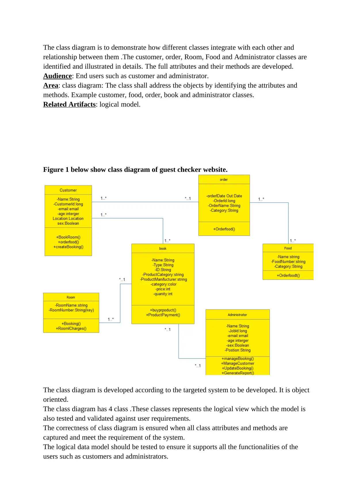
The class diagram is to demonstrate how different classes integrate with each other and
relationship between them .The customer, order, Room, Food and Administrator classes are
identified and illustrated in details. The full attributes and their methods are developed.
Audience: End users such as customer and administrator.
Area: class diagram: The class shall address the objects by identifying the attributes and
methods. Example customer, food, order, book and administrator classes.
Related Artifacts: logical model.
Figure 1 below show class diagram of guest checker website.
The class diagram is developed according to the targeted system to be developed. It is object
oriented.
The class diagram has 4 class .These classes represents the logical view which the model is
also tested and validated against user requirements.
The correctness of class diagram is ensured when all class attributes and methods are
captured and meet the requirement of the system.
The logical data model should be tested to ensure it supports all the functionalities of the
users such as customers and administrators.
Development View.
The development view focuses on the organization of the actual software modules in the
software-development environment. The software is packaged in small chunks-program
libraries or subsystems-that can be developed by one or more developers. The subsystems are
organized in a hierarchy of layers, each layer providing a narrow and well-defined interface
to the layers above it.
Components are related by “is submodule of”.
This where actual developing of the guest checker takes place the developer code the final by
using the language of their choice. The language going to be used to develop the system is
java languages. The java files with java class are customer, order, food,and administrator
classes.
Audience: System Developers.
Area: components and objects: The application shall be implemented using java language.
Related Artifacts: Development model.
Development environment.
Basically all the development work was done on Window 10 professional operating system
machine where all the programming IDE were installed and utilised.
Mobile application
The android mobile application was developed using Android studio IDE from Google which
replaced the Eclipse IDE that comes with the Android plug-in. This is due to the fact that
Android studio was made the default Android development editor and comes with the
Material designs framework recommended by Google for the Android applications.
Android applications are developed using the java programming language.
The minimum software development kit (SDK) was set to application programming interface
(API) level 14 and the targeted SDK was API level 23.
Choice of java programming language for mobile development.
The object oriented language such as java are used to development of the Android mobile
application offers inbuilt security features that include the following;
There is no need to use pointers like C/C++ that would cause unauthorized access to memory
blocks when other programs get the pointer values.
Exception handling concept
It enables java to capture a series of errors that helps developers to get rid of risk of crashing
the whole phone system.
Test code reusability
This allows the developers to re-use the code that has already been tested while developing
Java enterprise applications (Pressman, 2018).
⊘ This is a preview!⊘
Do you want full access?
Subscribe today to unlock all pages.
Trusted by 1+ million students worldwide
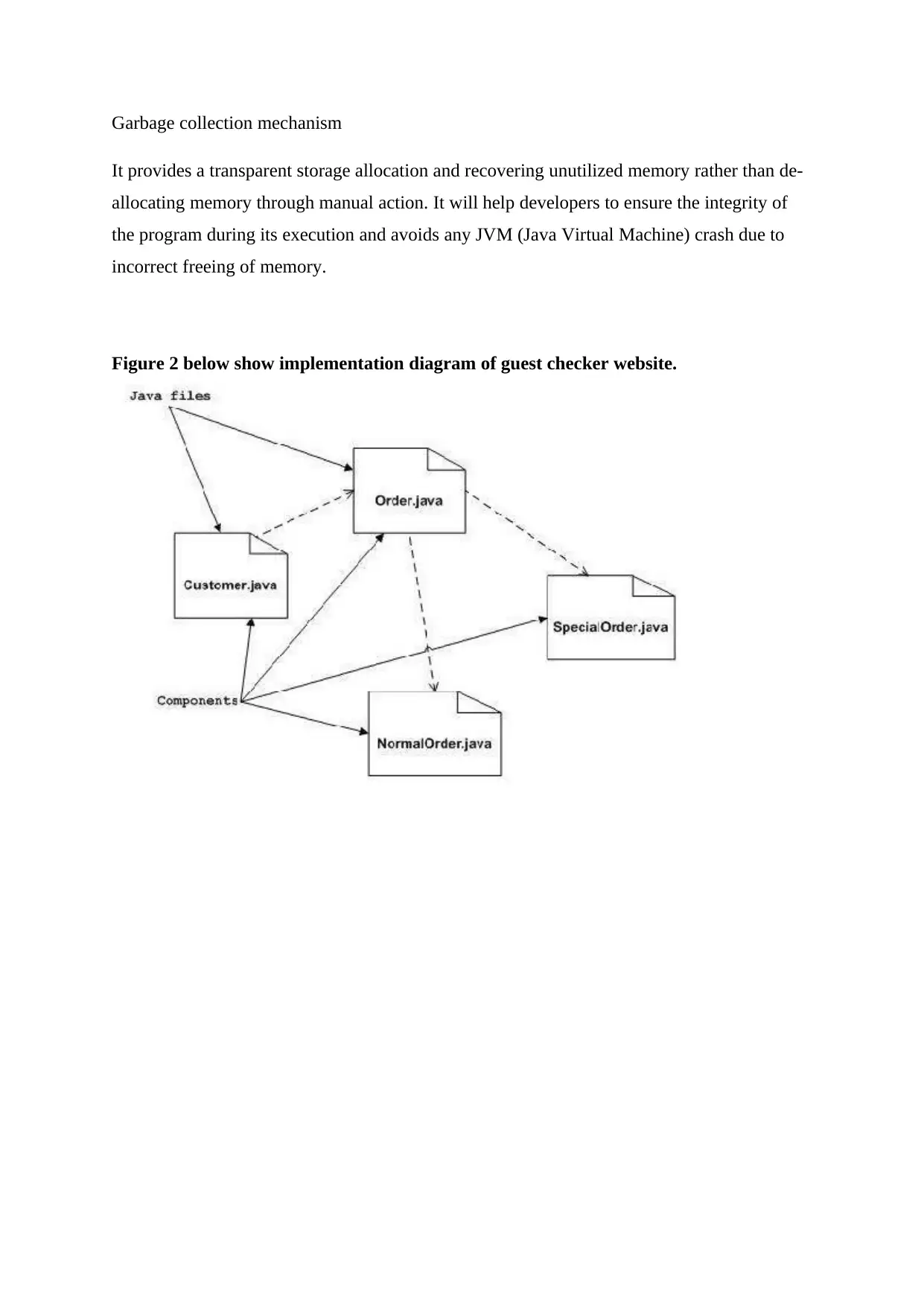
Garbage collection mechanism
It provides a transparent storage allocation and recovering unutilized memory rather than de-
allocating memory through manual action. It will help developers to ensure the integrity of
the program during its execution and avoids any JVM (Java Virtual Machine) crash due to
incorrect freeing of memory.
Figure 2 below show implementation diagram of guest checker website.
Paraphrase This Document
Need a fresh take? Get an instant paraphrase of this document with our AI Paraphraser

COMPONENT DESIGN
Class Method Pseudo code
Authentication Register()
Enter username AND AND password
Insert them into database
IF Error
PRINT Unsuccessful
ELSE
PRINT Added successful
Login()
Enter username AND password
Check user details in database
IF user exists
Grant Access
ELSE
Deny Access
ENDIF
Class Method Pseudo code
Authentication Register()
Enter username AND AND password
Insert them into database
IF Error
PRINT Unsuccessful
ELSE
PRINT Added successful
Login()
Enter username AND password
Check user details in database
IF user exists
Grant Access
ELSE
Deny Access
ENDIF
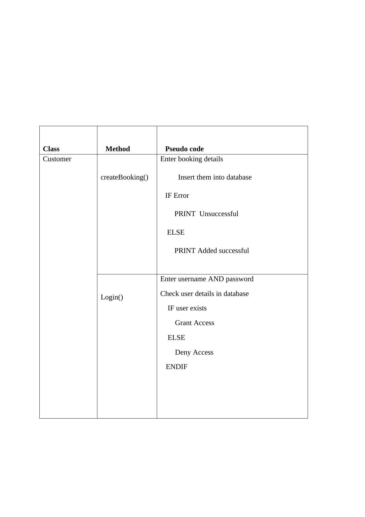
Class Method Pseudo code
Customer
createBooking()
Enter booking details
Insert them into database
IF Error
PRINT Unsuccessful
ELSE
PRINT Added successful
Login()
Enter username AND password
Check user details in database
IF user exists
Grant Access
ELSE
Deny Access
ENDIF
Customer
createBooking()
Enter booking details
Insert them into database
IF Error
PRINT Unsuccessful
ELSE
PRINT Added successful
Login()
Enter username AND password
Check user details in database
IF user exists
Grant Access
ELSE
Deny Access
ENDIF
⊘ This is a preview!⊘
Do you want full access?
Subscribe today to unlock all pages.
Trusted by 1+ million students worldwide
Physical View.
The physical view takes into account the system's nonfunctional requirements such as system
availability, reliability (fault-tolerance), performance (throughput), and
scalability(Sommerville, 2016). The software executes on a network of computers (the
processing nodes). The various elements identified in the logical, process, and development
views-networks, processes, tasks, and objects-must be mapped onto the various nodes.
Several different physical configurations will be used-some for development and testing,
others for system deployment at various sites or for different customers. The mapping of the
software to the nodes must therefore be highly flexible and have a minimal impact on the
source code itself.
This view illustrates how the guest checker system is installed and customers are able to use
it.
Audience: System Developers.
Area: Topology: The mapping of application to other devices such as desktop, server and
mobile devices.
Related Artifacts: Deployment model.
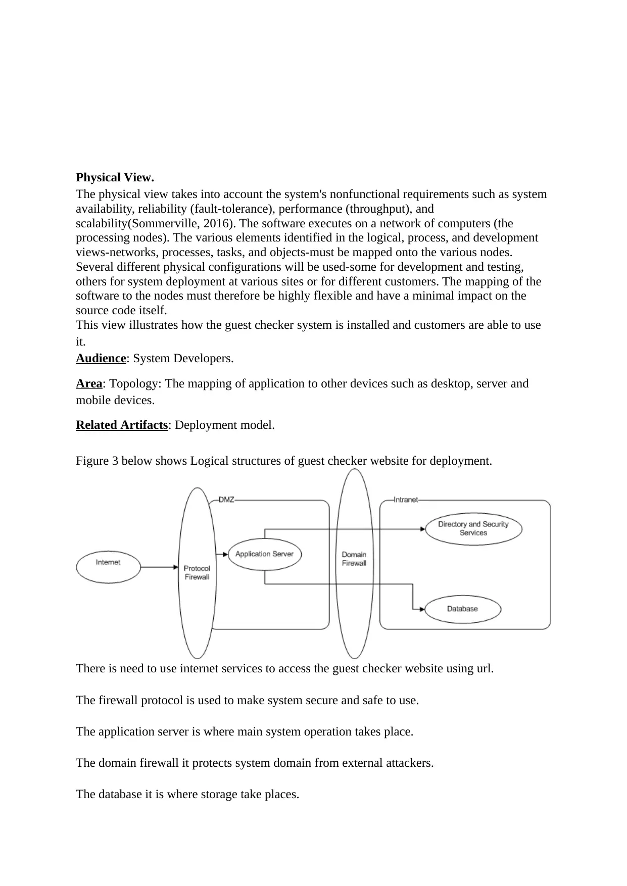
Figure 3 below shows Logical structures of guest checker website for deployment.
There is need to use internet services to access the guest checker website using url.
The firewall protocol is used to make system secure and safe to use.
The application server is where main system operation takes place.
The domain firewall it protects system domain from external attackers.
The database it is where storage take places.
The physical view takes into account the system's nonfunctional requirements such as system
availability, reliability (fault-tolerance), performance (throughput), and
scalability(Sommerville, 2016). The software executes on a network of computers (the
processing nodes). The various elements identified in the logical, process, and development
views-networks, processes, tasks, and objects-must be mapped onto the various nodes.
Several different physical configurations will be used-some for development and testing,
others for system deployment at various sites or for different customers. The mapping of the
software to the nodes must therefore be highly flexible and have a minimal impact on the
source code itself.
This view illustrates how the guest checker system is installed and customers are able to use
it.
Audience: System Developers.
Area: Topology: The mapping of application to other devices such as desktop, server and
mobile devices.
Related Artifacts: Deployment model.
Figure 3 below shows Logical structures of guest checker website for deployment.
There is need to use internet services to access the guest checker website using url.
The firewall protocol is used to make system secure and safe to use.
The application server is where main system operation takes place.
The domain firewall it protects system domain from external attackers.
The database it is where storage take places.
Paraphrase This Document
Need a fresh take? Get an instant paraphrase of this document with our AI Paraphraser
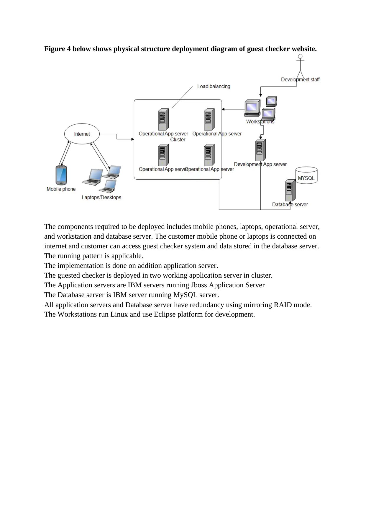
Figure 4 below shows physical structure deployment diagram of guest checker website.
The components required to be deployed includes mobile phones, laptops, operational server,
and workstation and database server. The customer mobile phone or laptops is connected on
internet and customer can access guest checker system and data stored in the database server.
The running pattern is applicable.
The implementation is done on addition application server.
The guested checker is deployed in two working application server in cluster.
The Application servers are IBM servers running Jboss Application Server
The Database server is IBM server running MySQL server.
All application servers and Database server have redundancy using mirroring RAID mode.
The Workstations run Linux and use Eclipse platform for development.
Process View.
The process view takes into account some nonfunctional requirements, such as performance
and system availability. It addresses concurrency and distribution, system integrity, and fault-
tolerance. The process view also specifies which thread of control executes each operation of
each class identified in the logical view(Sommerville, 2016).
So the process view describes the mapping of functions to runtime elements. It concerns the
dynamics of the system. A process is a group of tasks which form a logical unit. A process
can be started, stopped, resumed, etc., and there is communication between processes.
The customer interact with system by first registering, the system verify registration details
then system responds registration by accepting or being delayed. After registration the
customer login on the system .The system verify the login by allowing customer access
system features .The customer create booking and order food. The system administrator
manages customer preference by accepting or rejecting customer preference .The
administrator manages booking.
The figure below is a process interaction diagram. It mainly shows the runtime view of the
system.
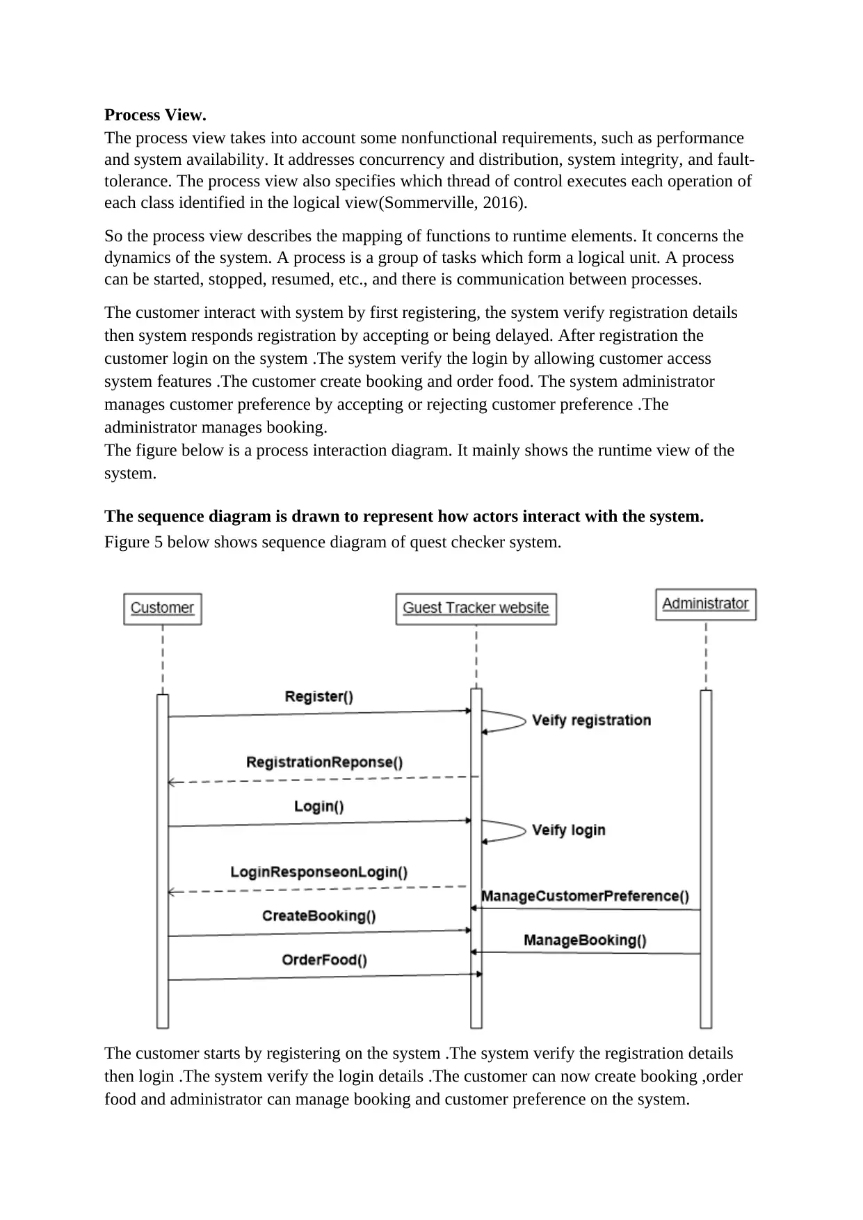
The sequence diagram is drawn to represent how actors interact with the system.
Figure 5 below shows sequence diagram of quest checker system.
The customer starts by registering on the system .The system verify the registration details
then login .The system verify the login details .The customer can now create booking ,order
food and administrator can manage booking and customer preference on the system.
The process view takes into account some nonfunctional requirements, such as performance
and system availability. It addresses concurrency and distribution, system integrity, and fault-
tolerance. The process view also specifies which thread of control executes each operation of
each class identified in the logical view(Sommerville, 2016).
So the process view describes the mapping of functions to runtime elements. It concerns the
dynamics of the system. A process is a group of tasks which form a logical unit. A process
can be started, stopped, resumed, etc., and there is communication between processes.
The customer interact with system by first registering, the system verify registration details
then system responds registration by accepting or being delayed. After registration the
customer login on the system .The system verify the login by allowing customer access
system features .The customer create booking and order food. The system administrator
manages customer preference by accepting or rejecting customer preference .The
administrator manages booking.
The figure below is a process interaction diagram. It mainly shows the runtime view of the
system.
The sequence diagram is drawn to represent how actors interact with the system.
Figure 5 below shows sequence diagram of quest checker system.
The customer starts by registering on the system .The system verify the registration details
then login .The system verify the login details .The customer can now create booking ,order
food and administrator can manage booking and customer preference on the system.
⊘ This is a preview!⊘
Do you want full access?
Subscribe today to unlock all pages.
Trusted by 1+ million students worldwide
1 out of 23
Related Documents


Your All-in-One AI-Powered Toolkit for Academic Success.
+13062052269
info@desklib.com
Available 24*7 on WhatsApp / Email
![[object Object]](/_next/static/media/star-bottom.7253800d.svg)
Unlock your academic potential
Copyright © 2020–2026 A2Z Services. All Rights Reserved. Developed and managed by ZUCOL.