Higher Colleges of Technology Dubai - MCE 2213 Beam Design Project
VerifiedAdded on 2022/12/23
|15
|1497
|3
Project
AI Summary
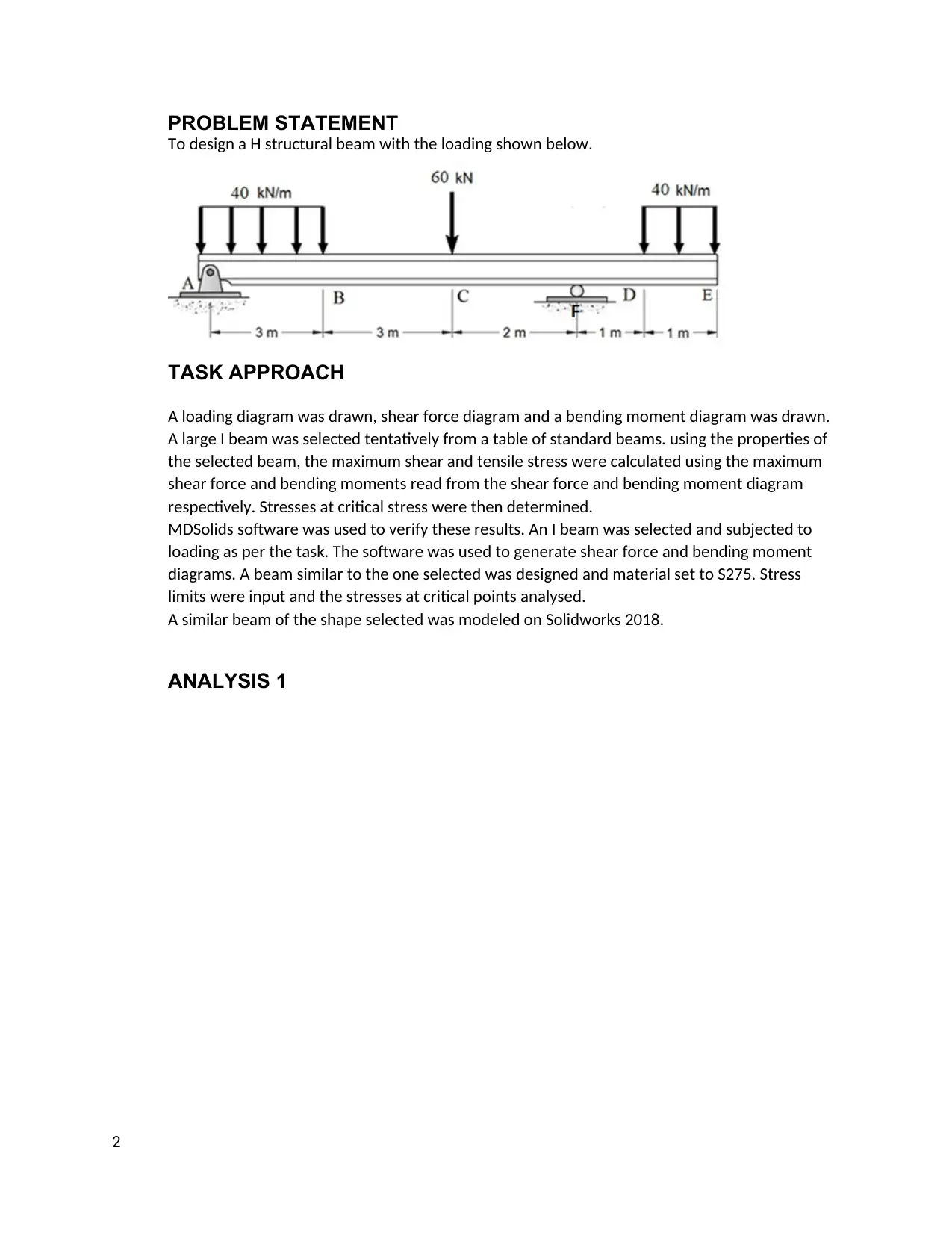
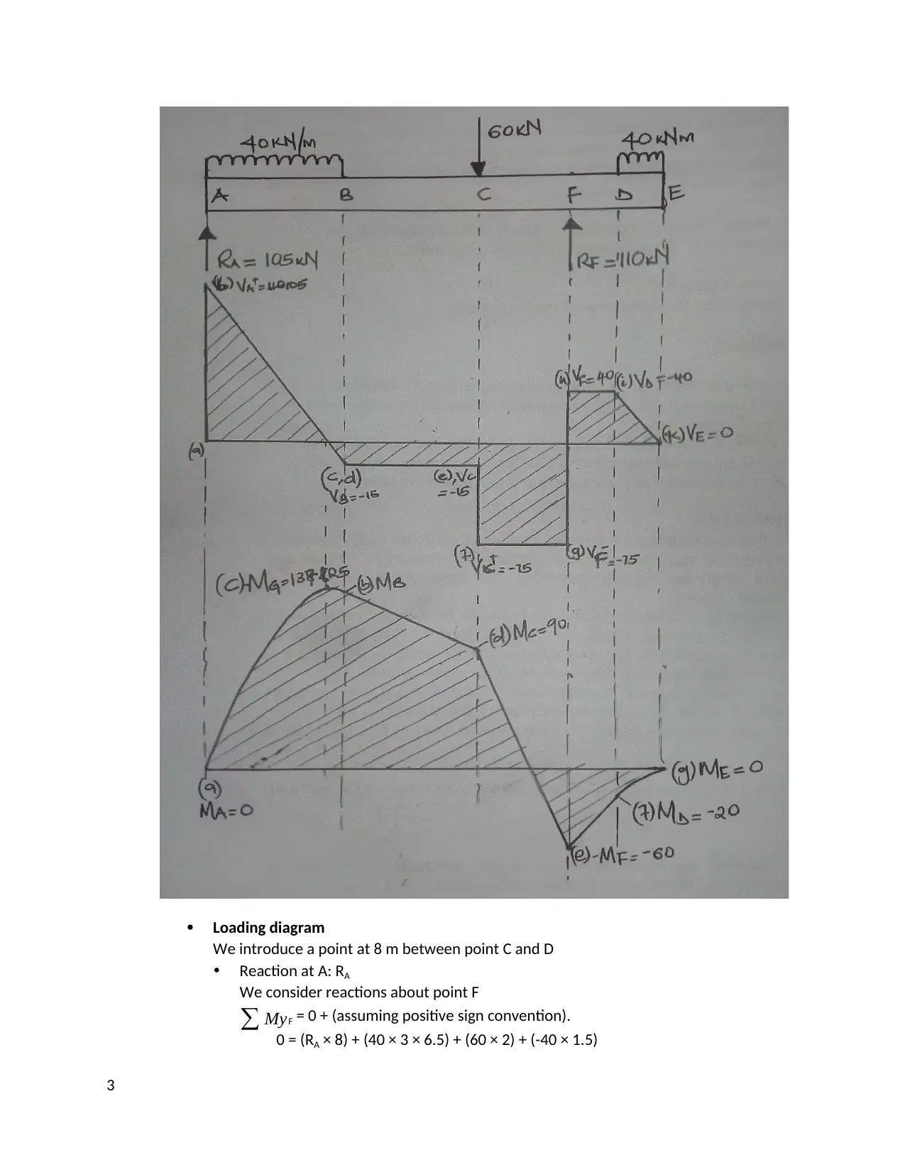
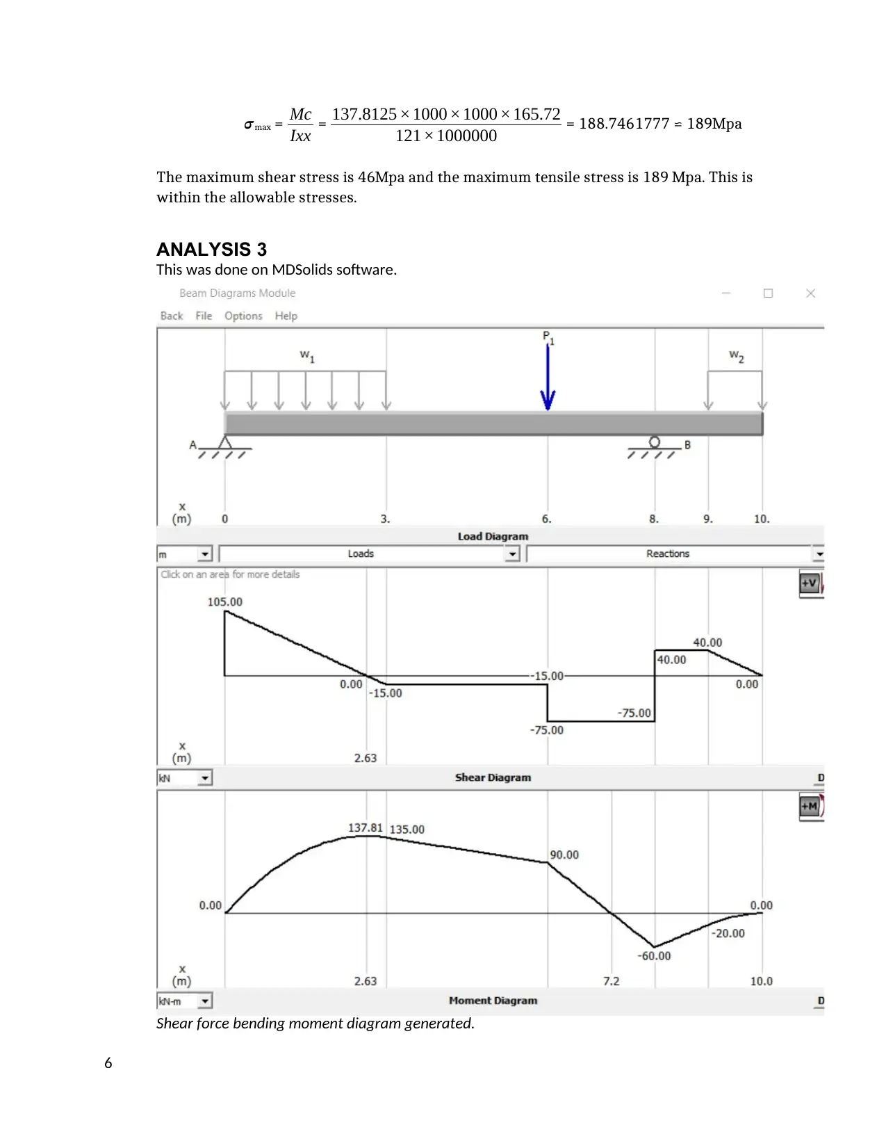
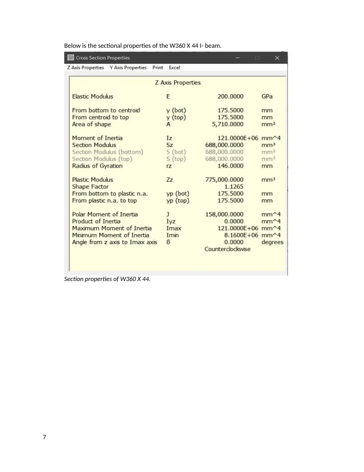
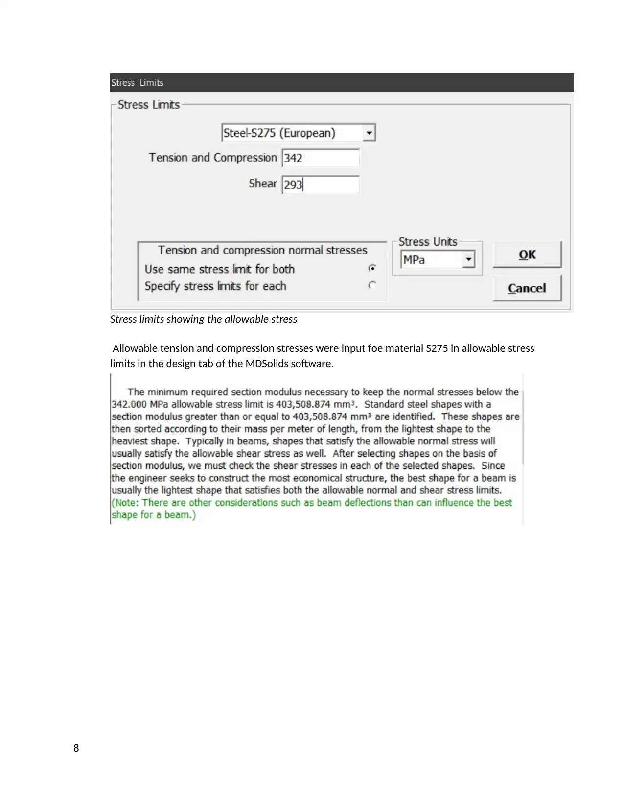
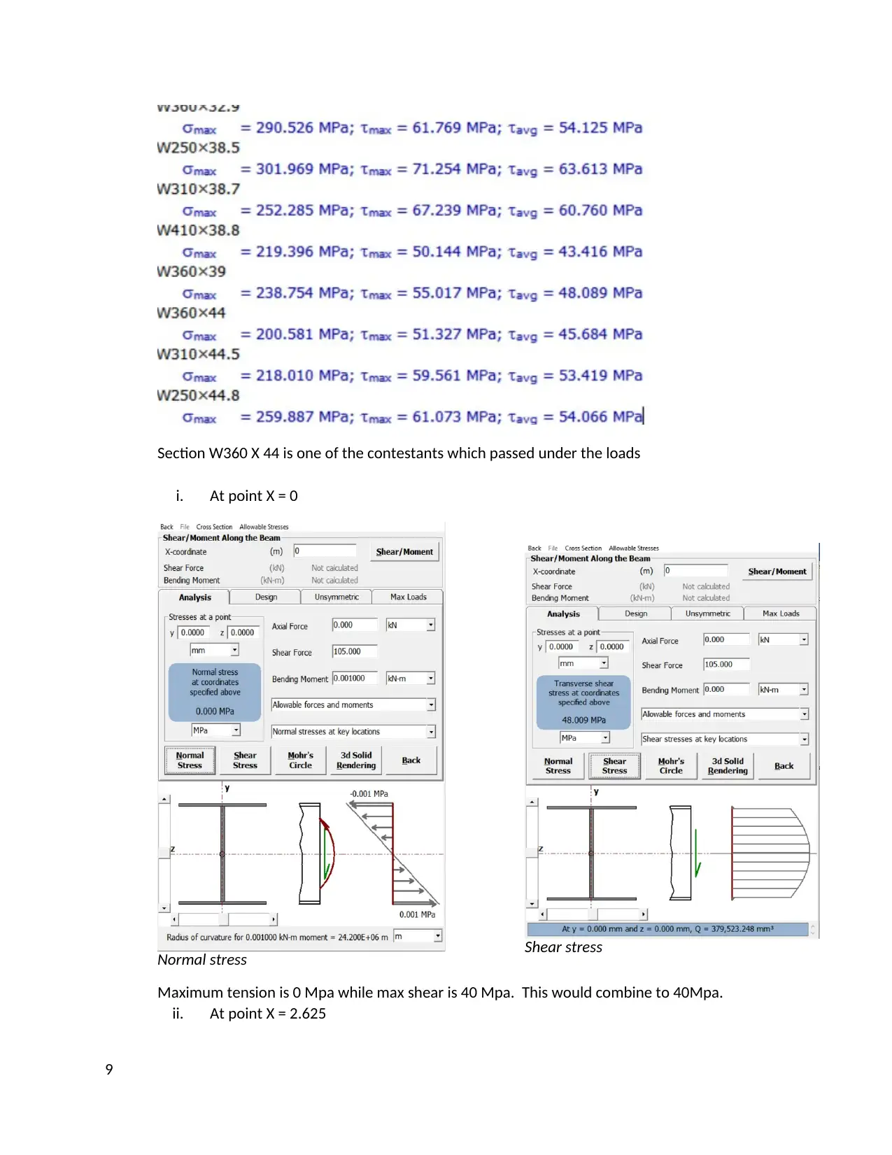
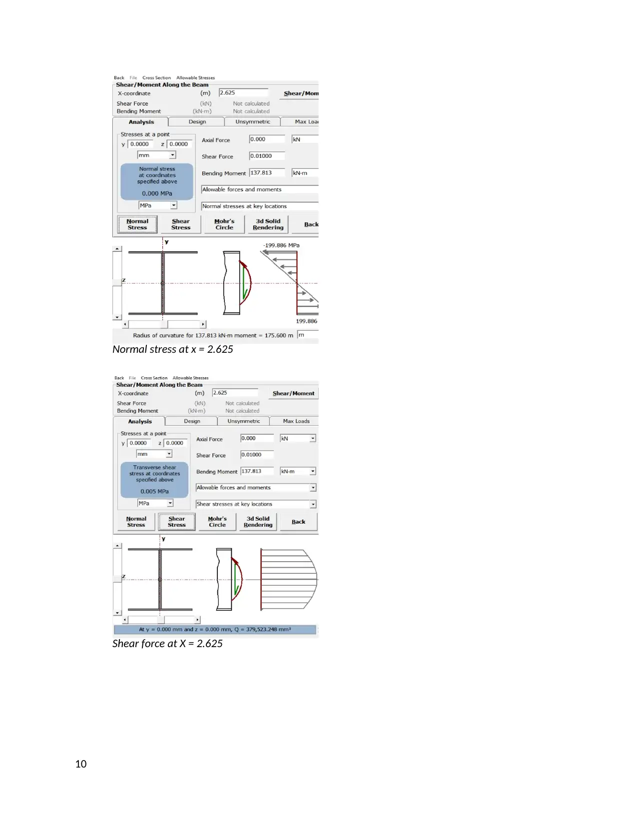
This project report details the design of a structural beam under specific loading conditions, a common task in mechanical engineering. The student begins by drawing a loading diagram and deriving shear force and bending moment diagrams to understand the internal forces acting on the beam. A standard I-beam is tentatively selected, and its properties are used to calculate maximum shear and tensile stresses. The student uses MDSolids software to verify these results and to analyze stress at critical points. The selected beam is modeled in Solidworks 2018. The report includes detailed calculations, diagrams, and software outputs, culminating in a discussion of the results and the selection of an appropriate beam. The report also includes an appendix showing the Solidworks model. The objective is to perform a complete prismatic beam design by drawing clear shear and moment diagrams of the beam based on maximum normal Bending stress.

HIGHER COLLEGES OF TECHNOLOGY-DUBAI
DEPARTMENT OF MECHANICAL ENGINEERING
MECHANICS 0F MATERIALS (MCE 2213)
ENGINEERING DESIGN PROBLEM
“COMPLETE BEAM DESIGN WITH MDSOLIDS VERIFICATION”
GROUP NAMES
a. .
b. .
0
DEPARTMENT OF MECHANICAL ENGINEERING
MECHANICS 0F MATERIALS (MCE 2213)
ENGINEERING DESIGN PROBLEM
“COMPLETE BEAM DESIGN WITH MDSOLIDS VERIFICATION”
GROUP NAMES
a. .
b. .
0
Paraphrase This Document
Need a fresh take? Get an instant paraphrase of this document with our AI Paraphraser

Contents
CONTENTS............................................................................................................................................... 1
PROBLEM STATEMENT............................................................................................................................ 1
TASK APPROACH...................................................................................................................................... 1
ANALYSIS 1.............................................................................................................................................. 1
ANALYSIS 2.............................................................................................................................................. 4
ANALYSIS 3.............................................................................................................................................. 5
RESULTS AND DISCUSSION.................................................................................................................... 11
APPENDIX.............................................................................................................................................. 11
1

PROBLEM STATEMENT
To design a H structural beam with the loading shown below.
TASK APPROACH
A loading diagram was drawn, shear force diagram and a bending moment diagram was drawn.
A large I beam was selected tentatively from a table of standard beams. using the properties of
the selected beam, the maximum shear and tensile stress were calculated using the maximum
shear force and bending moments read from the shear force and bending moment diagram
respectively. Stresses at critical stress were then determined.
MDSolids software was used to verify these results. An I beam was selected and subjected to
loading as per the task. The software was used to generate shear force and bending moment
diagrams. A beam similar to the one selected was designed and material set to S275. Stress
limits were input and the stresses at critical points analysed.
A similar beam of the shape selected was modeled on Solidworks 2018.
ANALYSIS 1
2
⊘ This is a preview!⊘
Do you want full access?
Subscribe today to unlock all pages.

Trusted by 1+ million students worldwide

Loading diagram
We introduce a point at 8 m between point C and D
Reaction at A: RA
We consider reactions about point F
∑ MyF = 0 + (assuming positive sign convention).
0 = (RA × 8) + (40 × 3 × 6.5) + (60 × 2) + (-40 × 1.5)
3
We introduce a point at 8 m between point C and D
Reaction at A: RA
We consider reactions about point F
∑ MyF = 0 + (assuming positive sign convention).
0 = (RA × 8) + (40 × 3 × 6.5) + (60 × 2) + (-40 × 1.5)
3
Paraphrase This Document
Need a fresh take? Get an instant paraphrase of this document with our AI Paraphraser

8RA = 780 + 120 – 60 = 840
RA = 105 kN
Reaction at F; RF
We consider reactions about point A
∑ MyF = 0 (assuming positive sign convention).
0 = (-40 × 3 × 1.5) + (-60 × 6) + 8RF + (-40 × 9.5)
8RF = 180 + 360 + 380 = 920
8RF = 110 kN
Shear force diagram, V
VA- = 0 kN ………. (Point a)
VA+ = RA = 105 kN ………. (Point b)
VB- = VA+ - area of ω- diagram]BA = 105 – (40 × 3) = -15kN ………. (Point c)
VB+ = VB- + 0 = -15 kN ………. (Point d)
(Point c and d are coincident).
VC- = VB+ + 0 = -15 kN ………. (Point e)
VC+ = VC- + PC = -15 + -60 = -75 kN ………. (Point f)
VF- = VC+ - area of ω- diagram]AF = -75 – 0 = -75 kN ………. (Point g)
VF+ = VF- + RF = -75 + 115 = 40 kN ………. (Point h)
VD- = VF+ - area of ω- diagram] FD = 40 – 0 = 40 kN ………. (Point i)
VD+ = VD+ - 0 = 40 kN ………. (Point j)
VE = VD+ - area of ω- diagram]DE = 40 – (40 - 1) = 0 kN ………. (Point k)
Bending Force Diagram
We introduce point G. (The X- intercept on the V- diagram).
MA = 0 ………. (Point a)
MB = MA + area of v-diagram]BA
= 0 + ( 1
2 ×105 × 2.625) – ( 1
2 × 15 × 0.375)
= 0 + 137.8125 – 2.8125
= 135 kNm ………. (Point c)
(The gradient between A and B is negative thus, the gradient of the parabola is negative
as well).
MG = -137.8125 ………. (Point b)
MC = MB + area of V- diagram] CB = 135 + (75 × 3) = 90 kNm ………. (Point d)
MF = MC + area of V- diagram] FC = 90 + (-75 × 2) = -60 kNm ………. (Point e)
MD = MF + area of V- diagram] DF = 60 × (40 × 1) = -20 kNm ………. (Point f)
ME = MD + area of V- diagram] ED = -20 + ( 40 ×1
2 ) = 0 kNm ……….
(Point g)
4

ANALYSIS 2
Selected beam: W360 X 44.
We should use a Safety factor of 1.2 in tension and compression and 1.4 in shear stress.
Allowable tensional stress = allowable stress of S 275
1.2 = 410 MPa
1.2 = 342 Mpa
Allowable shear stress = allowable stress of S 275
1.2 = 165 MPa
1.2 = 293 MPa
Maximum shear stress is obviously at the neutral axis. Thus, we analyze the stresses at the web
instead of the flanges.
For maximum shear stress, we consider the maximum shear stress. The maximum shear stress is
read from the shear force diagram of analysis 1. Its value is 105 kNm.
Moment of area A2;
Q2 = A2 y= ( 6.86 ×331.44
2 ) × 276.8
4 = 78669.27264
Moment of area A1;
Q1 = A1 y= (171 × 9.78) × 331.44+9.78
2 () = 285324.7518
Total moment of area;
Q1 + Q2 = 78669.27264 + 285324.7518
= 363994.0244
Maximum shear stress
tmax = VQ
I b = 105 ×1000 ×363994.0244
121×1000000 × 6.86 = 46.04411081 ⋍ 46 MPa
Maximum tensional and compression stress at any point
5
⊘ This is a preview!⊘
Do you want full access?
Subscribe today to unlock all pages.

Trusted by 1+ million students worldwide

𝝈max = Mc
Ixx = 137.8125 ×1000 ×1000 ×165.72
121×1000000 = 188.7461777 189Mpa⋍
The maximum shear stress is 46Mpa and the maximum tensile stress is 189 Mpa. This is
within the allowable stresses.
ANALYSIS 3
This was done on MDSolids software.
Shear force bending moment diagram generated.
6
Ixx = 137.8125 ×1000 ×1000 ×165.72
121×1000000 = 188.7461777 189Mpa⋍
The maximum shear stress is 46Mpa and the maximum tensile stress is 189 Mpa. This is
within the allowable stresses.
ANALYSIS 3
This was done on MDSolids software.
Shear force bending moment diagram generated.
6
Paraphrase This Document
Need a fresh take? Get an instant paraphrase of this document with our AI Paraphraser

Below is the sectional properties of the W360 X 44 I- beam.
Section properties of W360 X 44.
7
Section properties of W360 X 44.
7

Stress limits showing the allowable stress
Allowable tension and compression stresses were input foe material S275 in allowable stress
limits in the design tab of the MDSolids software.
8
Allowable tension and compression stresses were input foe material S275 in allowable stress
limits in the design tab of the MDSolids software.
8
⊘ This is a preview!⊘
Do you want full access?
Subscribe today to unlock all pages.

Trusted by 1+ million students worldwide

Section W360 X 44 is one of the contestants which passed under the loads
i. At point X = 0
Normal stress Shear stress
Maximum tension is 0 Mpa while max shear is 40 Mpa. This would combine to 40Mpa.
ii. At point X = 2.625
9
i. At point X = 0
Normal stress Shear stress
Maximum tension is 0 Mpa while max shear is 40 Mpa. This would combine to 40Mpa.
ii. At point X = 2.625
9
Paraphrase This Document
Need a fresh take? Get an instant paraphrase of this document with our AI Paraphraser

Normal stress at x = 2.625
Shear force at X = 2.625
10
Shear force at X = 2.625
10

11
⊘ This is a preview!⊘
Do you want full access?
Subscribe today to unlock all pages.

Trusted by 1+ million students worldwide
1 out of 15
Related Documents

Your All-in-One AI-Powered Toolkit for Academic Success.
+13062052269
info@desklib.com
Available 24*7 on WhatsApp / Email
Unlock your academic potential
Copyright © 2020–2025 A2Z Services. All Rights Reserved. Developed and managed by ZUCOL.