Analysis: Principles of Heat Transfer in Industrial Applications

Verified

Added on  2023/06/14

|8
|1402
|88
Report
AI Summary
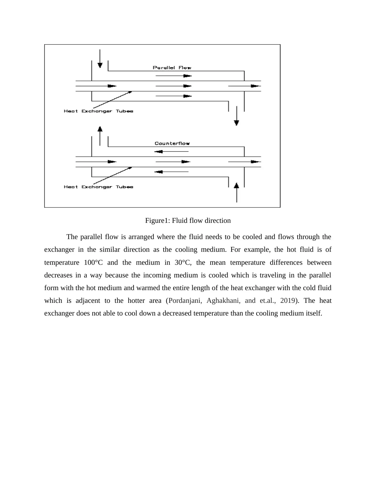
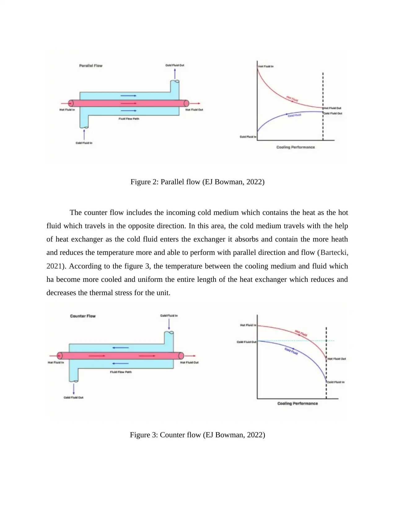
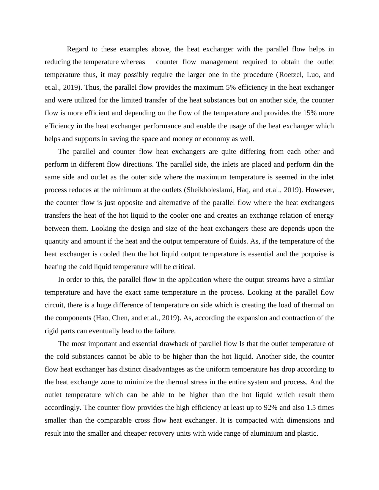
This report provides a detailed examination of heat transfer principles in industrial applications, focusing on the differentiation between parallel and counter-flow recuperative heat exchangers. It elucidates the operational mechanics of both types, highlighting that parallel flow involves fluids entering the exchanger at the same end and flowing in the same direction, while counter flow involves fluids flowing in opposite directions. The report further explains how parallel flow is suitable for cooling fluids, whereas counter flow is effective for achieving specific outlet temperatures, often requiring larger equipment. Efficiency comparisons reveal that counter flow exchangers, boasting up to 15% greater efficiency, are more effective and economical than parallel flow systems, which offer a maximum of 5% efficiency. The analysis extends to design considerations, noting that counter flow designs minimize thermal stress and can achieve higher outlet temperatures for the cooled liquid, making them compact and cost-effective for various applications. This document is available on Desklib, a platform offering a wide range of study resources for students.
tabler-icon-diamond-filled.svg

Contribute Materials

Your contribution can guide someone’s learning journey. Share your documents today.
Document Page
Examine the principles of heat
transfer to industrial
application
tabler-icon-diamond-filled.svg

Secure Best Marks with AI Grader

Need help grading? Try our AI Grader for instant feedback on your assignments.
Document Page
Document Page
TABLE OF CONTENTS
MAIN BODY..................................................................................................................................3
Task 5...............................................................................................................................................3
Differentiate between parallel and counter-flow recuperate heat exchangers.............................3
REFERENCES................................................................................................................................7
Document Page
MAIN BODY
Task 5
Differentiate between parallel and counter-flow recuperate heat exchangers.
In general, a heat exchanger is a structure and device which transfers the heat from one
medium to another one and includes the both heating and cooling process. There are two and
more fluids in between the heat exchanges and takes place. For example, the refrigerator use heat
exchangers to transform the heat from the groceries to the surrounding. Even there are different
exchangers in the building which heats the hot water ventilation system in the winter times and
seasons and indoor air to cooling in the summertime’s.
These heat exchangers are consisted of two concentric pipes of the different diameter
which are parallel flow and counter flow management. The parallel flow heat exchanger means
two fluids which enters the exchanger at the same period and duration at the same end and travel
in parallel manner to one another (Zhang, Zhu, Mondejar, and et.al., 2019). It is a pattern or
manner of liquid substances or gaseous state which is obtained by the heat exchanger where
fluids were divided by a wall flow in recognized direction as the heat travels through the wall.
In general, the cold and hot fluids enter and travel in same direction of the same end but
leaves at the ending position. On another hand, the counter flow defines the direction in which
the one flow is opposite to the another fluid. The both fluid travel in opposite direction to each
other till the same end (Hamzah, and Nima, 2020). These both heat exchangers are quite
different from each other as one is travelling and flowing till the san end with the same direction
and another one is performing in the opposite direction.
tabler-icon-diamond-filled.svg

Secure Best Marks with AI Grader

Need help grading? Try our AI Grader for instant feedback on your assignments.
Document Page
Figure1: Fluid flow direction
The parallel flow is arranged where the fluid needs to be cooled and flows through the
exchanger in the similar direction as the cooling medium. For example, the hot fluid is of
temperature 100°C and the medium in 30°C, the mean temperature differences between
decreases in a way because the incoming medium is cooled which is traveling in the parallel
form with the hot medium and warmed the entire length of the heat exchanger with the cold fluid
which is adjacent to the hotter area (Pordanjani, Aghakhani, and et.al., 2019). The heat
exchanger does not able to cool down a decreased temperature than the cooling medium itself.
Document Page
Figure 2: Parallel flow (EJ Bowman, 2022)
The counter flow includes the incoming cold medium which contains the heat as the hot
fluid which travels in the opposite direction. In this area, the cold medium travels with the help
of heat exchanger as the cold fluid enters the exchanger it absorbs and contain the more heath
and reduces the temperature more and able to perform with parallel direction and flow (Bartecki,
2021). According to the figure 3, the temperature between the cooling medium and fluid which
ha become more cooled and uniform the entire length of the heat exchanger which reduces and
decreases the thermal stress for the unit.
Figure 3: Counter flow (EJ Bowman, 2022)
Document Page
Regard to these examples above, the heat exchanger with the parallel flow helps in
reducing the temperature whereas counter flow management required to obtain the outlet
temperature thus, it may possibly require the larger one in the procedure (Roetzel, Luo, and
et.al., 2019). Thus, the parallel flow provides the maximum 5% efficiency in the heat exchanger
and were utilized for the limited transfer of the heat substances but on another side, the counter
flow is more efficient and depending on the flow of the temperature and provides the 15% more
efficiency in the heat exchanger performance and enable the usage of the heat exchanger which
helps and supports in saving the space and money or economy as well.
The parallel and counter flow heat exchangers are quite differing from each other and
perform in different flow directions. The parallel side, the inlets are placed and perform din the
same side and outlet as the outer side where the maximum temperature is seemed in the inlet
process reduces at the minimum at the outlets (Sheikholeslami, Haq, and et.al., 2019). However,
the counter flow is just opposite and alternative of the parallel flow where the heat exchangers
transfers the heat of the hot liquid to the cooler one and creates an exchange relation of energy
between them. Looking the design and size of the heat exchangers these are depends upon the
quantity and amount if the heat and the output temperature of fluids. As, if the temperature of the
heat exchanger is cooled then the hot liquid output temperature is essential and the porpoise is
heating the cold liquid temperature will be critical.
In order to this, the parallel flow in the application where the output streams have a similar
temperature and have the exact same temperature in the process. Looking at the parallel flow
circuit, there is a huge difference of temperature on side which is creating the load of thermal on
the components (Hao, Chen, and et.al., 2019). As, according the expansion and contraction of the
rigid parts can eventually lead to the failure.
The most important and essential drawback of parallel flow Is that the outlet temperature of
the cold substances cannot be able to be higher than the hot liquid. Another side, the counter
flow heat exchanger has distinct disadvantages as the uniform temperature has drop according to
the heat exchange zone to minimize the thermal stress in the entire system and process. And the
outlet temperature which can be able to be higher than the hot liquid which result them
accordingly. The counter flow provides the high efficiency at least up to 92% and also 1.5 times
smaller than the comparable cross flow heat exchanger. It is compacted with dimensions and
result into the smaller and cheaper recovery units with wide range of aluminium and plastic.
tabler-icon-diamond-filled.svg

Paraphrase This Document

Need a fresh take? Get an instant paraphrase of this document with our AI Paraphraser
Document Page
REFERENCES
Books and Journals
Bartecki, K., 2021. An Approximate Transfer Function Model for a Double-Pipe Counter-Flow
Heat Exchanger. Energies. 14(14), p.4174.
Hamzah, J.A. and Nima, M.A., 2020. Experimental study of heat transfer enhancement in
double-pipe heat exchanger integrated with metal foam fins. Arabian Journal for Science
and Engineering. 45(7), pp.5153-5167.
Hao, J.H., Chen, Q., and et.al., 2019. A new modeling and analysis method of the indirect
evaporative heat exchanger based on the heat current perspective. Applied Thermal
Engineering. 163, p.114331.
Pordanjani, A.H., Aghakhani, S., and et.al., 2019. An updated review on application of
nanofluids in heat exchangers for saving energy. Energy Conversion and
Management, 198. p.111886.
Roetzel, W., Luo, X. et.al., 2019. Design and Operation of Heat Exchangers and Their Networks.
Academic Press.
Sheikholeslami, M., Haq, R.U., and et.al., 2019. Heat transfer simulation of heat storage unit
with nanoparticles and fins through a heat exchanger. International Journal of Heat and
Mass Transfer. 135, pp.470-478.
Zhang, J., Zhu, X., Mondejar, and et.al., 2019. A review of heat transfer enhancement techniques
in plate heat exchangers. Renewable and Sustainable Energy Reviews. 101, pp.305-328.
Online
EJ Bowman, 2022. [Online]. Accessed through https://ej-bowman.com/knowledge-centre/what-
is-counter-flow-why-is-it-more-efficient/
Engineer edge, 2022. [Online]. Accessed through
https://www.engineersedge.com/heat_transfer/parallel_counter_flow_designs.htm
Completed file (Task 5)
chevron_up_icon
1 out of 8
circle_padding
hide_on_mobile
zoom_out_icon
logo.png

Your All-in-One AI-Powered Toolkit for Academic Success.

Available 24*7 on WhatsApp / Email

[object Object]