Detailed Comparison of Parallel and Counter-Flow Heat Exchangers

Verified

Added on  2023/06/14

|8
|1352
|218
Report
AI Summary
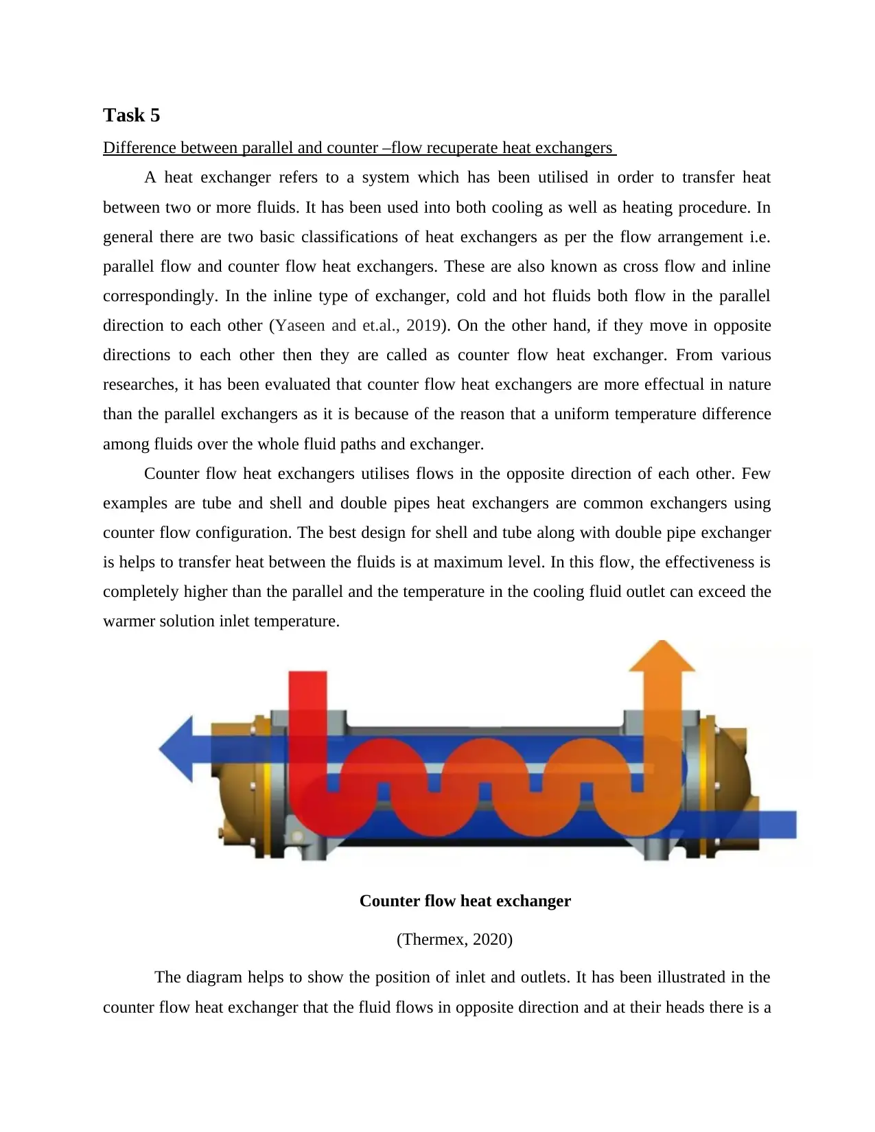
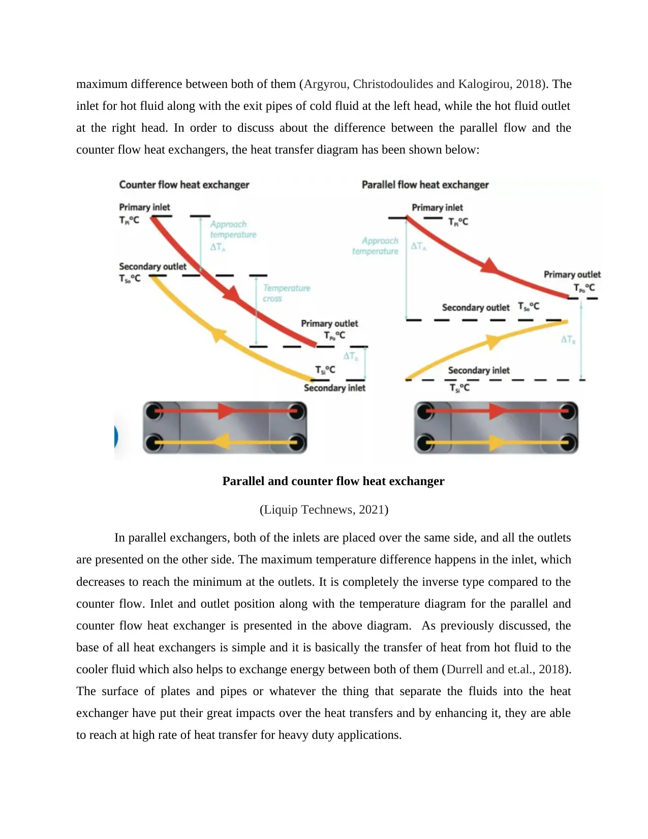
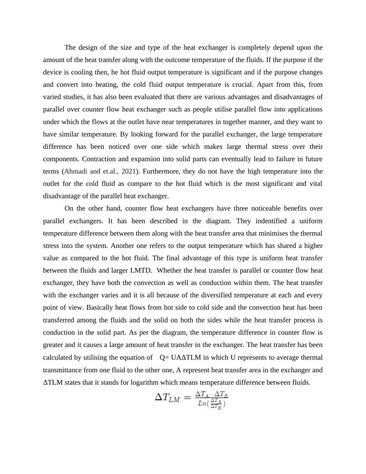
This report provides a detailed comparison between parallel and counter-flow heat exchangers, highlighting their differences in flow arrangement, efficiency, and applications. It explains that counter-flow heat exchangers are generally more effective due to a more uniform temperature difference between fluids. The report discusses the inlet and outlet positions for both types, noting the temperature gradients and thermal stresses associated with each design. Parallel flow exchangers are suitable for applications requiring similar outlet temperatures, while counter-flow exchangers offer higher outlet temperatures for the cold fluid and minimize thermal stress. The heat transfer mechanisms, involving both convection and conduction, are also examined, along with the impact of temperature differences on heat transfer rates, as described by the equation Q= UAΔTLM. The report concludes by referencing relevant books, journals, and online resources.
Document Page
APPLY THE STEADY
FLOW ENERGY
EQUATION TO PLANT
EQUIPMENT
tabler-icon-diamond-filled.svg

Paraphrase This Document

Need a fresh take? Get an instant paraphrase of this document with our AI Paraphraser
Document Page
Table of Contents
Task 5...............................................................................................................................................3
Difference between parallel and counter –flow recuperate heat exchangers...............................3
REFERENCES................................................................................................................................1
Document Page
Task 5
Difference between parallel and counter –flow recuperate heat exchangers
A heat exchanger refers to a system which has been utilised in order to transfer heat
between two or more fluids. It has been used into both cooling as well as heating procedure. In
general there are two basic classifications of heat exchangers as per the flow arrangement i.e.
parallel flow and counter flow heat exchangers. These are also known as cross flow and inline
correspondingly. In the inline type of exchanger, cold and hot fluids both flow in the parallel
direction to each other (Yaseen and et.al., 2019). On the other hand, if they move in opposite
directions to each other then they are called as counter flow heat exchanger. From various
researches, it has been evaluated that counter flow heat exchangers are more effectual in nature
than the parallel exchangers as it is because of the reason that a uniform temperature difference
among fluids over the whole fluid paths and exchanger.
Counter flow heat exchangers utilises flows in the opposite direction of each other. Few
examples are tube and shell and double pipes heat exchangers are common exchangers using
counter flow configuration. The best design for shell and tube along with double pipe exchanger
is helps to transfer heat between the fluids is at maximum level. In this flow, the effectiveness is
completely higher than the parallel and the temperature in the cooling fluid outlet can exceed the
warmer solution inlet temperature.
Counter flow heat exchanger
(Thermex, 2020)
The diagram helps to show the position of inlet and outlets. It has been illustrated in the
counter flow heat exchanger that the fluid flows in opposite direction and at their heads there is a
Document Page
maximum difference between both of them (Argyrou, Christodoulides and Kalogirou, 2018). The
inlet for hot fluid along with the exit pipes of cold fluid at the left head, while the hot fluid outlet
at the right head. In order to discuss about the difference between the parallel flow and the
counter flow heat exchangers, the heat transfer diagram has been shown below:
Parallel and counter flow heat exchanger
(Liquip Technews, 2021)
In parallel exchangers, both of the inlets are placed over the same side, and all the outlets
are presented on the other side. The maximum temperature difference happens in the inlet, which
decreases to reach the minimum at the outlets. It is completely the inverse type compared to the
counter flow. Inlet and outlet position along with the temperature diagram for the parallel and
counter flow heat exchanger is presented in the above diagram. As previously discussed, the
base of all heat exchangers is simple and it is basically the transfer of heat from hot fluid to the
cooler fluid which also helps to exchange energy between both of them (Durrell and et.al., 2018).
The surface of plates and pipes or whatever the thing that separate the fluids into the heat
exchanger have put their great impacts over the heat transfers and by enhancing it, they are able
to reach at high rate of heat transfer for heavy duty applications.
tabler-icon-diamond-filled.svg

Paraphrase This Document

Need a fresh take? Get an instant paraphrase of this document with our AI Paraphraser
Document Page
The design of the size and type of the heat exchanger is completely depend upon the
amount of the heat transfer along with the outcome temperature of the fluids. If the purpose if the
device is cooling then, he hot fluid output temperature is significant and if the purpose changes
and convert into heating, the cold fluid output temperature is crucial. Apart from this, from
varied studies, it has also been evaluated that there are various advantages and disadvantages of
parallel over counter flow heat exchanger such as people utilise parallel flow into applications
under which the flows at the outlet have near temperatures in together manner, and they want to
have similar temperature. By looking forward for the parallel exchanger, the large temperature
difference has been noticed over one side which makes large thermal stress over their
components. Contraction and expansion into solid parts can eventually lead to failure in future
terms (Ahmadi and et.al., 2021). Furthermore, they do not have the high temperature into the
outlet for the cold fluid as compare to the hot fluid which is the most significant and vital
disadvantage of the parallel heat exchanger.
On the other hand, counter flow heat exchangers have three noticeable benefits over
parallel exchangers. It has been described in the diagram. They indentified a uniform
temperature difference between them along with the heat transfer area that minimises the thermal
stress into the system. Another one refers to the output temperature which has shared a higher
value as compared to the hot fluid. The final advantage of this type is uniform heat transfer
between the fluids and larger LMTD. Whether the heat transfer is parallel or counter flow heat
exchanger, they have both the convection as well as conduction within them. The heat transfer
with the exchanger varies and it is all because of the diversified temperature at each and every
point of view. Basically heat flows from hot side to cold side and the convection heat has been
transferred among the fluids and the solid on both the sides while the heat transfer process is
conduction in the solid part. As per the diagram, the temperature difference in counter flow is
greater and it causes a large amount of heat transfer in the exchanger. The heat transfer has been
calculated by utilising the equation of Q= UAΔTLM in which U represents to average thermal
transmittance from one fluid to the other one, A represent heat transfer area in the exchanger and
ΔTLM states that it stands for logarithm which means temperature difference between fluids.
Document Page
A small change within the temperature can lead to a large LMTD in the exchanger for
instance for a 70 degree Celsius and 80 degree Celsius temperature of the inlet and the outlet in
one flow and a 40 degree Celsius and 44 degree Celsius for the other flow, the LMTD is 6.55
degree Celsius. By an enhancement of 2 degree Celsius in the first flow, the increase of 11% in
the LMTD is a significant amount (Huntingford and et.al., 2019).
Document Page
REFERENCES
Books and journals
Ahmadi, A., and et.al., 2021. Recent residential applications of low-temperature solar
collector. Journal of Cleaner Production, 279, p.123549.
Argyrou, M.C., Christodoulides, P. and Kalogirou, S.A., 2018. Energy storage for electricity
generation and related processes: Technologies appraisal and grid scale
applications. Renewable and Sustainable Energy Reviews, 94, pp.804-821.
Durrell, J.H., and et.al., 2018. Bulk superconductors: a roadmap to applications. Superconductor
science and technology, 31(10), p.103501.
Huntingford, C., and et.al., 2019. Machine learning and artificial intelligence to aid climate
change research and preparedness. Environmental Research Letters, 14(12), p.124007.
Yaseen, Z.M., and et.al., 2019. An enhanced extreme learning machine model for river flow
forecasting: State-of-the-art, practical applications in water resource engineering area
and future research direction. Journal of Hydrology, 569, pp.387-408.
Online
Thermax, 2020. [Online]. Available Through: < https://thermex.co.uk/>.
Liquip Technews, 2021. [Online]. Available Through: https://www.linquip.com/blog/counter-
flow-heat-exchangers/>.
1
tabler-icon-diamond-filled.svg

Paraphrase This Document

Need a fresh take? Get an instant paraphrase of this document with our AI Paraphraser
Document Page
2
chevron_up_icon
1 out of 8
circle_padding
hide_on_mobile
zoom_out_icon
[object Object]