Comparative Analysis: High-Rise Building Design Approaches (Civil Eng)
VerifiedAdded on 2021/08/30
|19
|3839
|131
Report
AI Summary
This report provides a comparative analysis of performance-based design (PBD) and force-based design (FBD) approaches for high-rise concrete buildings, focusing on their response to wind and earthquake loads. The study investigates the impact of multihazard loading on building behavior, highlighting the advantages of predicting responses in preliminary design stages for optimal building orientation. The report compares wind and earthquake loads, emphasizing that earthquake loads excite higher modes, leading to higher acceleration, while wind loads cause longer-duration acceleration, which is a comfort issue. It also examines the application of British Standard and Eurocode for load combinations and design considerations, including dead loads, live loads, and wind loads. The report emphasizes the importance of performance-based design in limiting damage and maintaining functionality after earthquakes. Finally, the report discusses the design of beams, columns, and bracing systems, and load calculations for both standards.
COMPARISON OF PERFORMANCE BASED DESIGN AND FORCED BASED DESIGN
APPROACH FOR HIGH RISE CONCRETE BUILDING
ABSTRACT:
The main objective of this report is the understanding of the impact of multihazard loading, broug
wind and earthquakes, on the behavior of high-rise buildings, in order to apply such knowledge to
The main contributions of the current study are summarized as follows:
(i)For dynamics and response under wind loads, general agreements between the results of the pr
integration technique and the aeroelastic experiment exist. However, the effect of the aerodynam
damping on the worst responses of a multi story building/highrise in the two lateral directions is s
to be positive, which resulted in partial response reduction.
(ii)The study that will be discussed in this project report will show that it is advantageous to predic
responses of tall buildings in their preliminary design stages as this can provide an opportunity to
the building to an optimal orientation that can lead to significant reduction in the responses. The r
will show that the worst peak acceleration is reduced by 38.5%, by rotating the building (multi sto
building/highrise) to a suggested orientation. This reduction is achieved without adding any struct
elements/components to the primary building (no additional cost).
(iii)The results that will be done for load calculations in this project will show that wind and earthq
loads are different from each other and are also different from static loads. This comes from the s
comparison of the response of a high-rise building under the two types of excitation. The results in
that earthquake loads excite higher modes that produce less interstory drift but higher acceleratio
occurs for a relatively short time (compared to wind loads)..
(iv)Although the acceleration under wind loads is lower than that under earthquake loads, it occur
longer periods that become a comfort issue.
(v)It seems that tall buildings designed for wind are safe under moderate earthquake loads. Never
it is important to mention that, even if the interstory drift ratios in tall buildings may be relatively
with no significant apparent issues for the main force resisting system of the structure, nonstructu
systems may represent a high percentage of loss exposure of buildings to earthquakes due to hig
acceleration. Accordingly, appropriate damping techniques are recommended for response reduct
under wind and earthquake loads.
Seismic design of structures is commonly based on strength or force considerations rather than
displacement as the seismic design codes generally use lateral inertia forces to account for seism
motion effects. The distribution of these static forces (and therefore, stiffness and strength) is bas
implicitly on the elastic vibration modes [1, 2]. Therefore, as structures exceed their elastic limits
severe earthquakes, the use of inertia forces corresponding to elastic modes may not lead to the
distribution of structural properties [2, 3]. The need for finding cost-efficient and optimum structur
designs has led to the development of different structural optimization methodologies. Optimum d
structures for seismic loads has been studied by many researchers over the past decades [4-8]. T
conventional methods used in these studies are usually gradient-based solution strategies that re
satisfaction of some specific mathematical conditions. Due to the difficulty in calculating appropria
Paraphrase This Document
Need a fresh take? Get an instant paraphrase of this document with our AI Paraphraser
expressions for optimisation constraints, these methods cannot be practically applied for optimum
of nonlinear structures subjected to seismic excitations.
INTRODUCTION:
In today‟s era the aim of limiting excessive damage and to maintain functionality of the building a
earthquake is becoming more desirable. In order to predict damage to a structure in an earthquak
performance based design method is a new method which is rapidly gaining popularity. It is well k
that structures designed by current codes undergo large inelastic deformations during high earthq
However, current seismic design approach is generally based on elastic analysis. The seismic desi
structures is continuously evolving. Conventional design procedures have the objective of achievin
safety in a structure by providing sufficient strength and ductility to resist whole or partial collapse
structure. Structures designed according to current seismic design provisions or design code shou
general, satisfy the following rules. First, to resist minor level of earthquake ground motions witho
damage; second, to resist moderate earthquakes without structural damage, but may experience
structural damage; and finally, to resist major earthquakes without collapse, but possibly with som
structural and/or non-structural damage. The unexpectedly high financial losses related to functio
downtime and non-structural damage from recent large earthquakes near prime locations emphas
limitations behind the current ductile designs using FBD method. In the current Indian design prac
is common to calculate design base shear from code specified spectral acceleration, with the assu
that structure to behave elastic. It is also reduced by response reduction factor R. the design force
influenced by importance factor I, based on occupancy. By the use of these parameters lateral for
found, member size will be selected from design results and then analysis regarding drift and defl
the structure is done, which must be within an acceptable limit. Sometime the structures experien
earthquake forces however, the structures designed by such procedures have been found to unde
inelastic deformations in a somewhat „uncontrolled‟ manner. This may results undesirable and
unpredictable behavior, sometimes total collapse, or difficult and costly repair works. So the socie
requirements are pushing the practice to achieving higher levels of performance, safety and econ
including life-cycle costs. Performance Based Plastic Design is a recent designing concept of seism
resistant structure, in which the design criteria are expressed in terms of achieving stated perform
objectives when the structure is subjected to higher level of seismic hazards. Since 1994 Northbri
earthquake and other earthquakes in the world during the end of 20th century led the structural e
to use the concept of Performance based design.
DESIGN OF A STRUCTURE OF HIGHRISE BUILDING AND ITS CALCULATIONS:
Structures tare ta tgroup tsuch tas tbeams, tcolumns, tslabs, tfoundations, tgirders, tand ttrusse
twork tas ta tunit tto tfulfill ta tpurpose. tAn tengineer's tduty tis tto tdesign tstructures tin ta tpro
tsafe, tand teconomical tmanner tin torder tto tfulfill tthe tpurpose tfor twhich tit twas tdesigned t
tfirst tplace. tStructures tas tclassified tinto teither tbeing tstatically tdeterminate tor tstatically
tindeterminate.
Statically tdeterminate tstructures tare tstructures tthat tcan tbe tanalyzed tusing tstatics tequa
t(i.e., tequilibrium tin tall tdirections). tOn tthe tother thand, tstatically tindeterminate tstructures
tanalyzed tusing tstatics tequations tonly; tthey trequire tother tmaterial tproperties, tsuch tas
tdeformations, tin torder tto tanalyze tthem.When tengineers tconduct tstructural tanalysis, tthey
tthe treaction tforces tdue tto tthe texternal tforces tapplied tto tthe tstructure tas twell tas tinter
tsuch tas tthe tbending tmoment, tshear tforce, tand tnormal tforce. tStructural tanalysis tis tnece
tstructural tdesign tin torder tfor tthe tstructural tengineer tto tchoose tthe tproper tsizes tand tm
tthe tstructure tcan teconomically tand teffectively tresist tthe teffects tof tthe tpossible texternal
tapplied tto tit.
METHADOLOGY OF STRUCTURE DESIGN
This tproject tcompare tbraced tand tunbraced tframes tapplied tto teuro tcode tEC tand tBritish
tBS5950.
Method tused tto tcompare tare thand tcalculation, tand tsoftware tsuch tas tstrand7 tand
tanalysis. tAs tan tengineer twe tknow tthat tone tonly ttrial twouldn’t tbe tsatisfactory tto
ta tpoint, tso tit thas tbeen tcreated tbuilding tfor teach tprocedure tand teach tprocedure
tdesigning tof tEUROCODE tand tBRITISH tSTANDARD twith ttwo tdifferent tdimensions tas
tdimensions tcan taffect tthe tbuckling tand tbending tof tthe tmember, tand tP-delta tfac
tbeen tanalysed.
Drawing tare tbeen tmade ton tAUTOCADt(figure1) tthen ttransferred tto trobot tfor tthe
tanalysis.
After teach tmember tdesign, ta ttype tof tcross tsectional tarea tis tbeen tchosen tfrom t
tbook tbased ton ttheir tresistance tformulated ton tthe tcalculation.
LOAD TYPE
Dead tLoad
Dead tload tas twell tas tknown tas tthe tpermanent tload. tAll tthe tmembers ttaking tpar
tthe tstructure tand tkeeping ttogether tthe tstructure tare tcalled tdead tLoads, tas teach
town tweight tand teffects tthe tstiffens tof tthe tnext tpermanent tmember. tGood texam
tslab, tbeam tcolumn, troof, tcladding tetc. In torder tto thave ta tsecure tand tdurable tm
tsafety tfactor tis tused. tAs tof tthe tEuro-code timply ta tfactor tof t1.35, tand tBS tstand
timply t1.4.
⊘ This is a preview!⊘
Do you want full access?
Subscribe today to unlock all pages.
Trusted by 1+ million students worldwide
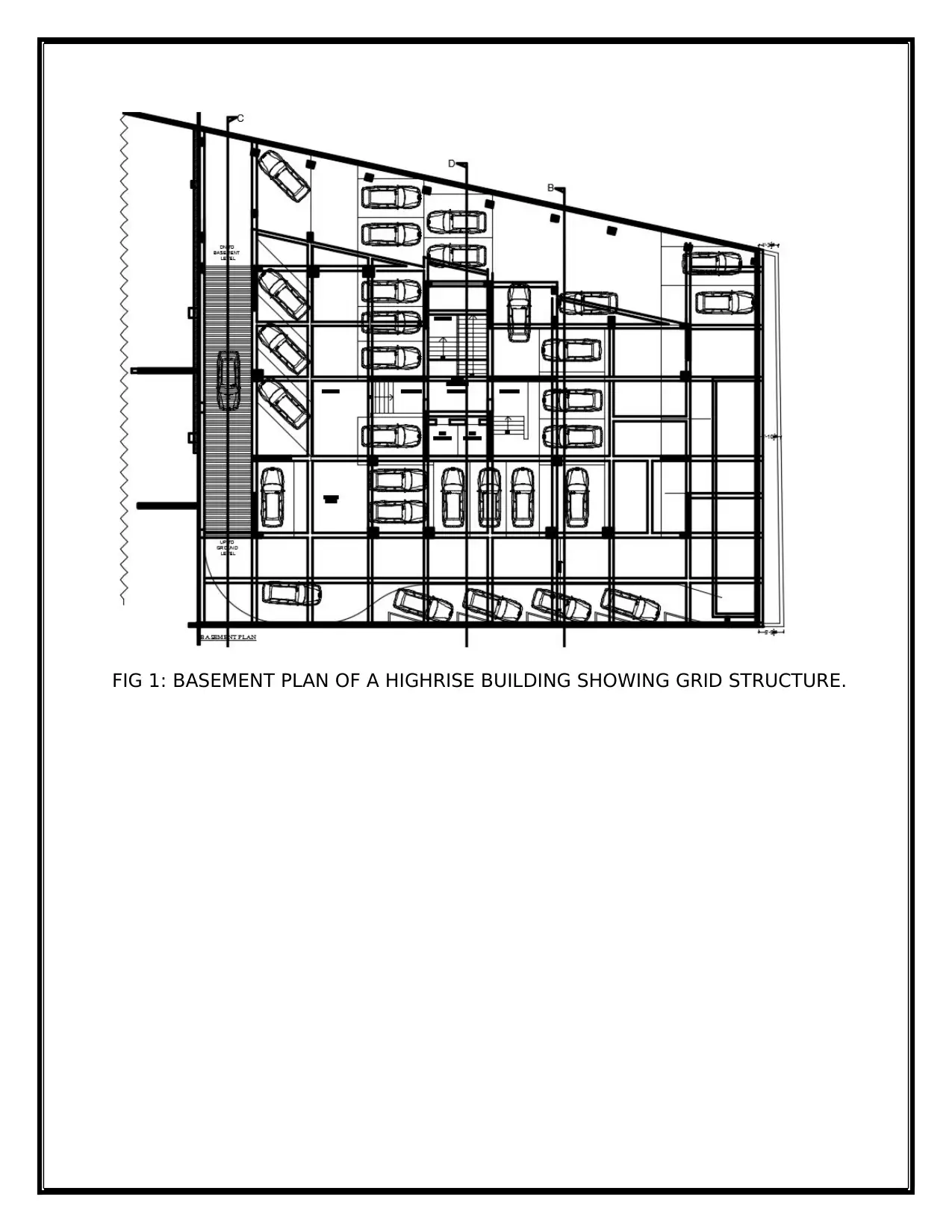
FIG 1: BASEMENT PLAN OF A HIGHRISE BUILDING SHOWING GRID STRUCTURE.
Paraphrase This Document
Need a fresh take? Get an instant paraphrase of this document with our AI Paraphraser
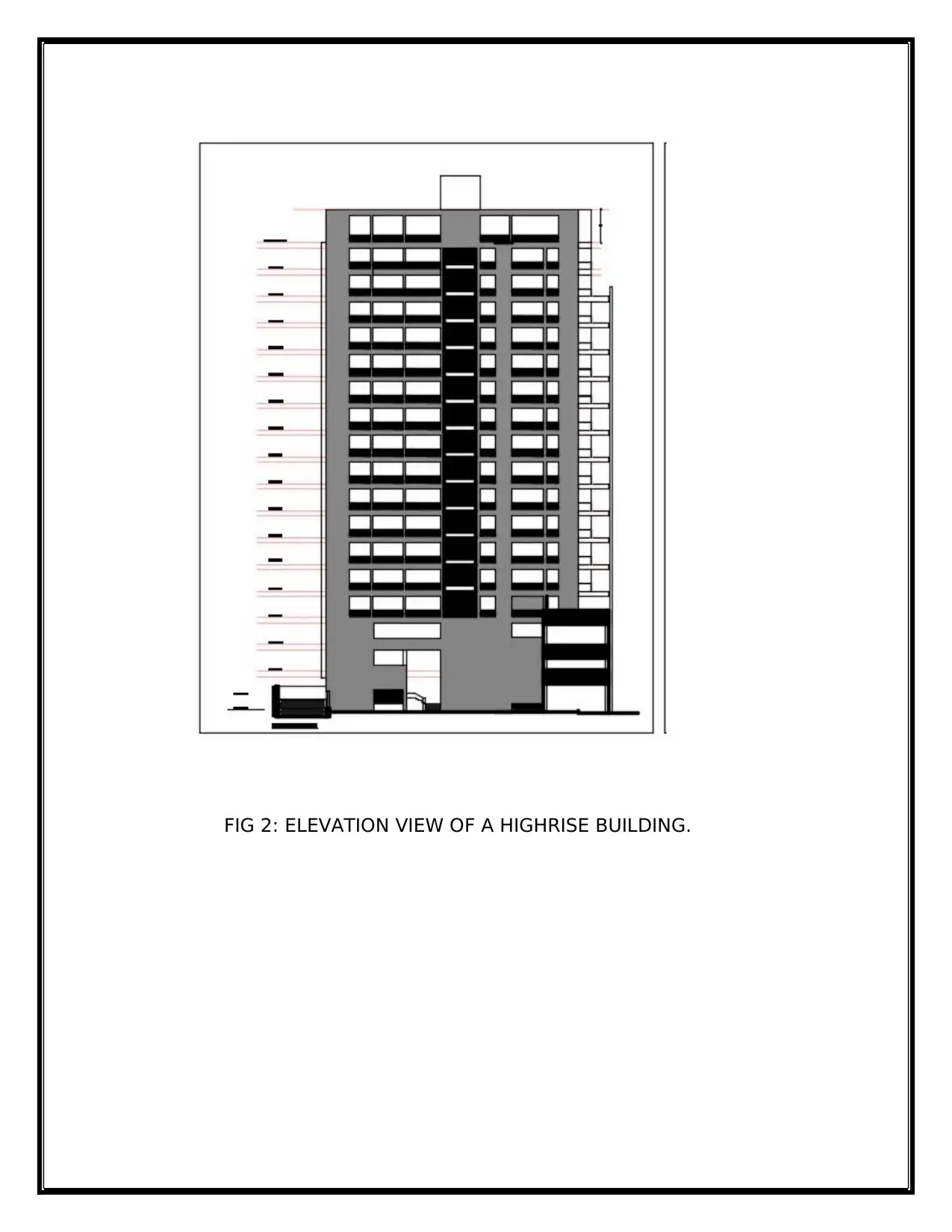
FIG 2: ELEVATION VIEW OF A HIGHRISE BUILDING.
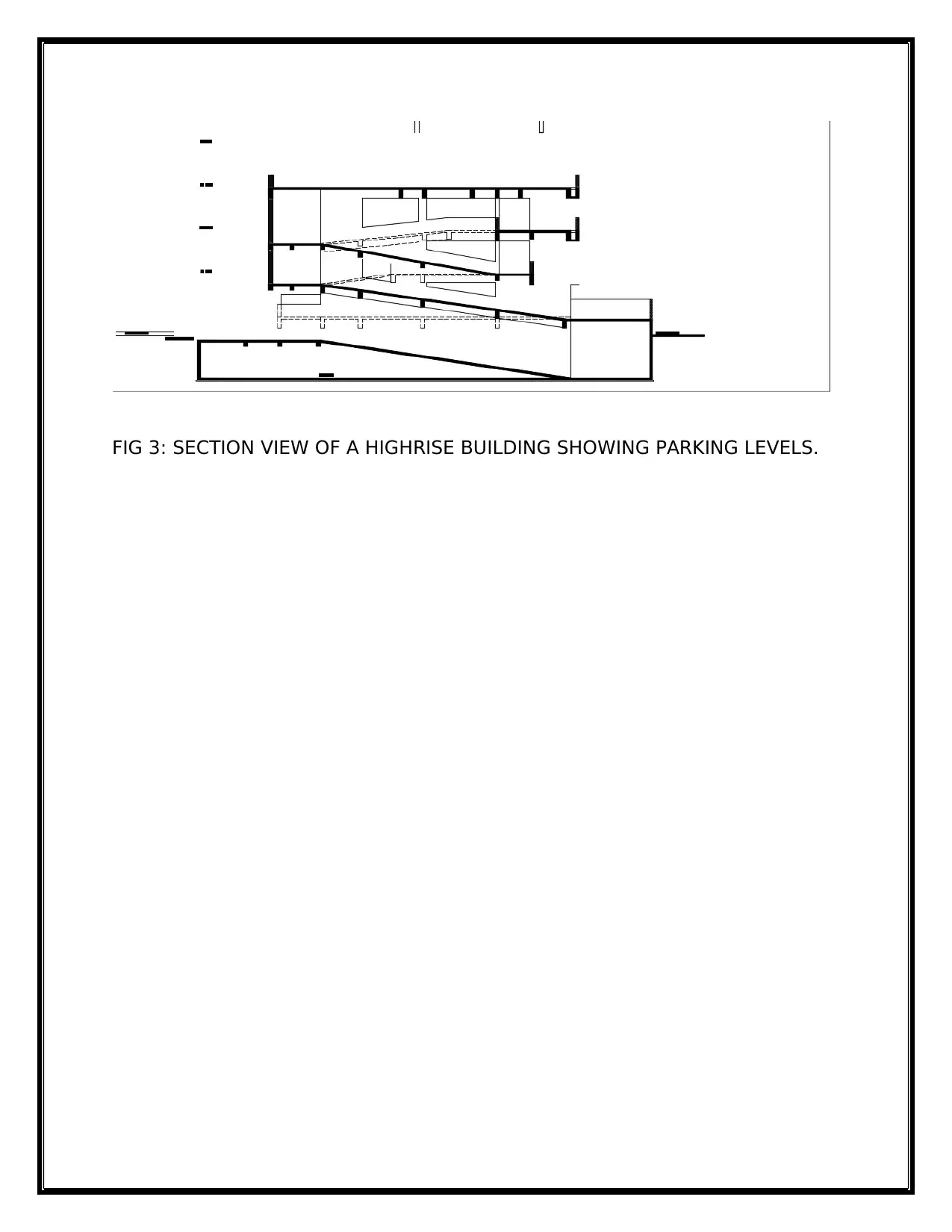
FIG 3: SECTION VIEW OF A HIGHRISE BUILDING SHOWING PARKING LEVELS.
⊘ This is a preview!⊘
Do you want full access?
Subscribe today to unlock all pages.
Trusted by 1+ million students worldwide
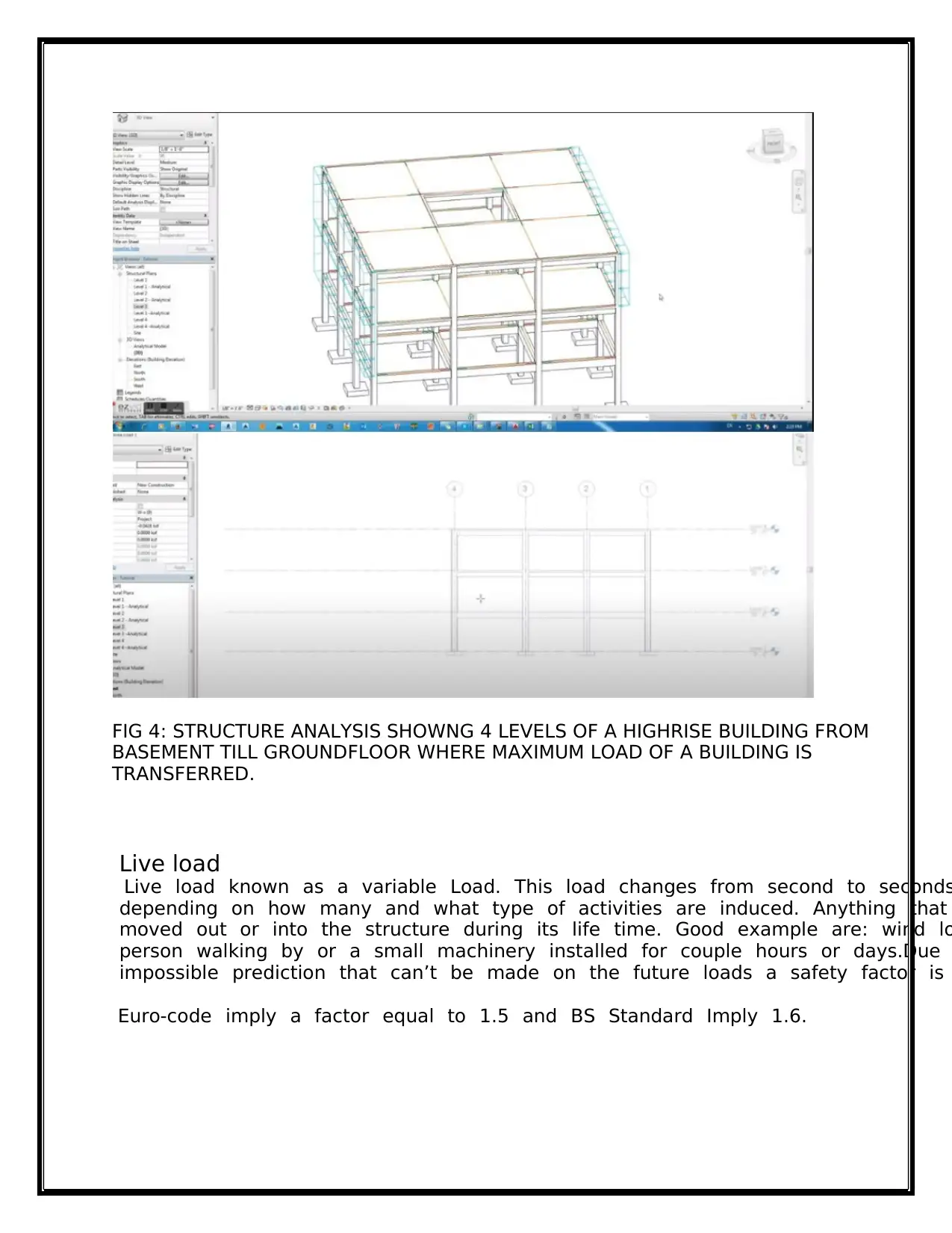
FIG 4: STRUCTURE ANALYSIS SHOWNG 4 LEVELS OF A HIGHRISE BUILDING FROM
BASEMENT TILL GROUNDFLOOR WHERE MAXIMUM LOAD OF A BUILDING IS
TRANSFERRED.
Live load
Live tload tknown tas ta tvariable tLoad. tThis tload tchanges tfrom tsecond tto tseconds
tdepending ton thow tmany tand twhat ttype tof tactivities tare tinduced. tAnything tthat
tmoved tout tor tinto tthe tstructure tduring tits tlife ttime. tGood texample tare: twind tlo
tperson twalking tby tor ta tsmall tmachinery tinstalled tfor tcouple thours tor tdays.Due t
timpossible tprediction tthat tcan’t tbe tmade ton tthe tfuture tloads ta tsafety tfactor tis t
Euro-code timply ta tfactor tequal tto t1.5 tand tBS tStandard tImply t1.6. t
Paraphrase This Document
Need a fresh take? Get an instant paraphrase of this document with our AI Paraphraser
DESIGN FOR THE ULTIMATE LIMIT STATE
Load combinations BRITISH STANDARD
t
The tcombination tloads tconsidered tin tthis tproject tare tas tfollow:
1.4 t× tDead tload t+ t1.6 t× tImposed tload t+ t1.0 t× tNotional thorizontal tforces
tCombination t1
1.2 t× tDead tload t+ t1.2 t× tImposed tload t+ t1.2 t× tWind tload tCombination t2
1.4 t× tDead tload t+ t1.4 t× tWind tload tCombination t3
The tnotional thorizontal tforces tshould tbe ttaken tas t0.5% tof tthe tfactored tdea
timposed tloads t(BS t5950-1:1990 tClauses t5.6.3, t5.1.2.3).
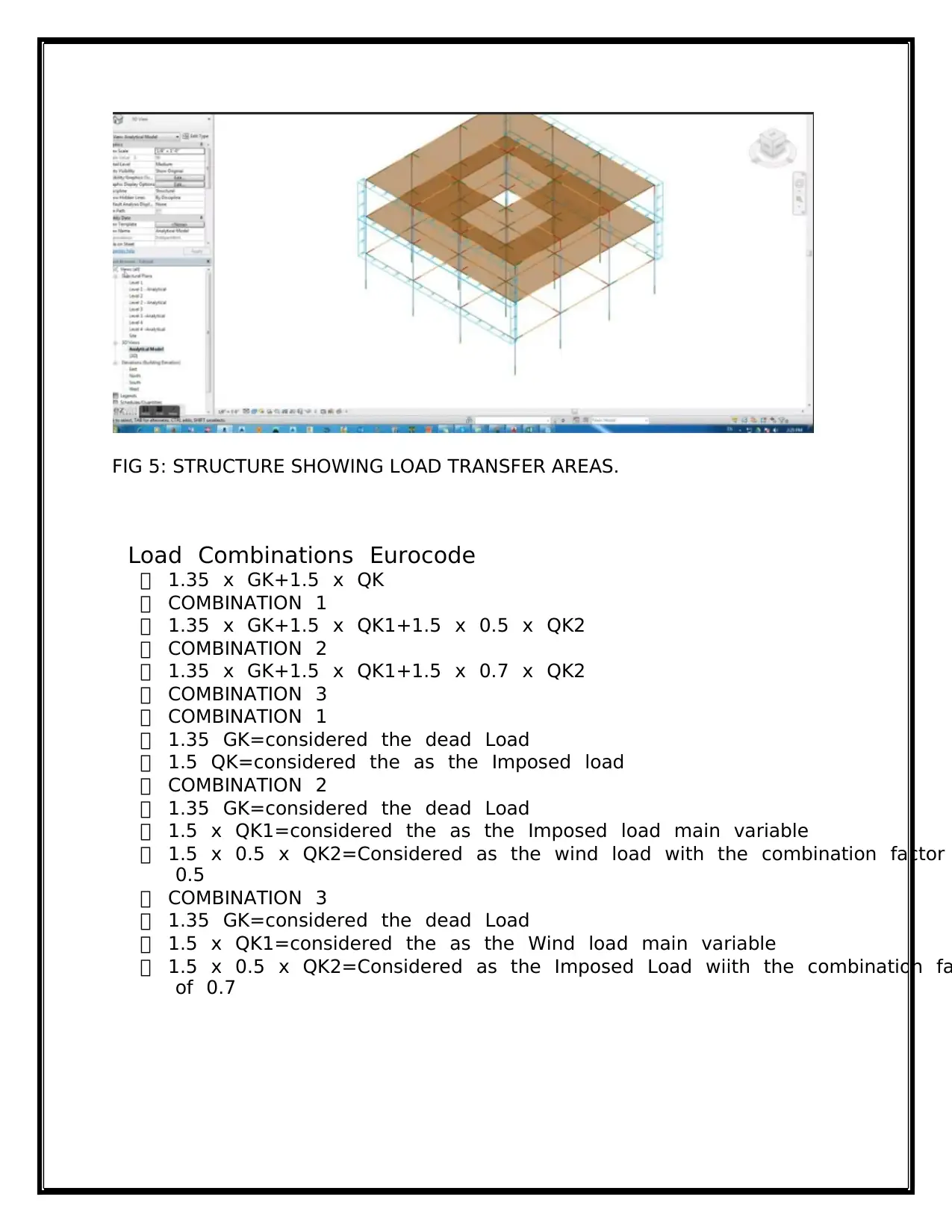
FIG 5: STRUCTURE SHOWING LOAD TRANSFER AREAS.
tLoad tCombinations tEurocode
1.35 tx tGK+1.5 tx tQK
COMBINATION t1
1.35 tx tGK+1.5 tx tQK1+1.5 tx t0.5 tx tQK2
COMBINATION t2
1.35 tx tGK+1.5 tx tQK1+1.5 tx t0.7 tx tQK2
COMBINATION t3
COMBINATION t1
1.35 tGK=considered tthe tdead tLoad
1.5 tQK=considered tthe tas tthe tImposed tload
COMBINATION t2
1.35 tGK=considered tthe tdead tLoad
1.5 tx tQK1=considered tthe tas tthe tImposed tload tmain tvariable
1.5 tx t0.5 tx tQK2=Considered tas tthe twind tload twith tthe tcombination tfactor t
t0.5
COMBINATION t3
1.35 tGK=considered tthe tdead tLoad
1.5 tx tQK1=considered tthe tas tthe tWind tload tmain tvariable
1.5 tx t0.5 tx tQK2=Considered tas tthe tImposed tLoad twiith tthe tcombination tfa
tof t0.7
⊘ This is a preview!⊘
Do you want full access?
Subscribe today to unlock all pages.
Trusted by 1+ million students worldwide
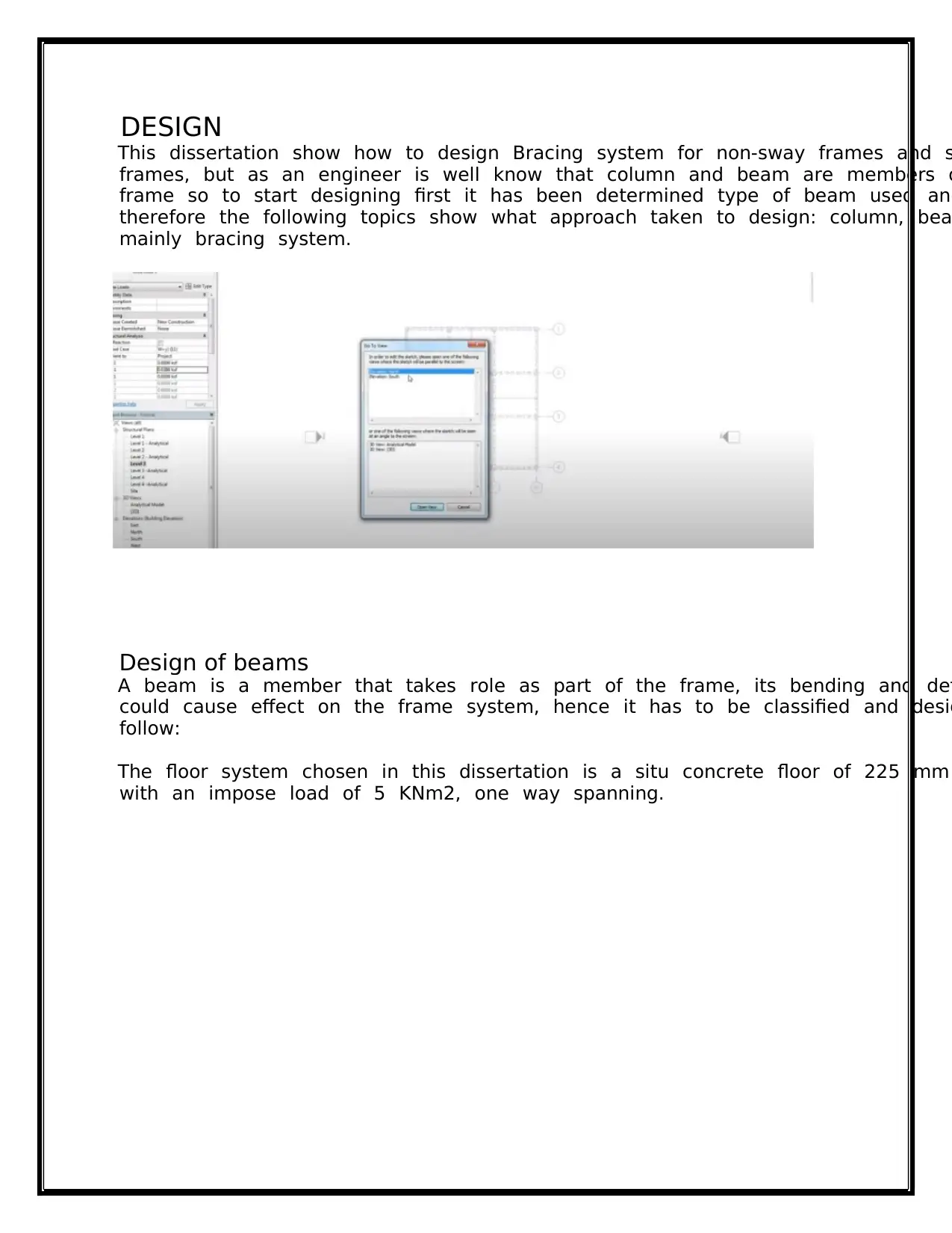
DESIGN
This tdissertation tshow thow tto tdesign tBracing tsystem tfor tnon-sway tframes tand ts
tframes, tbut tas tan tengineer tis twell tknow tthat tcolumn tand tbeam tare tmembers to
tframe tso tto tstart tdesigning tfirst tit thas tbeen tdetermined ttype tof tbeam tused tand
ttherefore tthe tfollowing ttopics tshow twhat tapproach ttaken tto tdesign: tcolumn, tbea
tmainly tbracing tsystem.
Design of beams
A tbeam tis ta tmember tthat ttakes trole tas tpart tof tthe tframe, tits tbending tand tdefl
tcould tcause teffect ton tthe tframe tsystem, thence tit thas tto tbe tclassified tand tdesig
tfollow:
The tfloor tsystem tchosen tin tthis tdissertation tis ta tsitu tconcrete tfloor tof t225 tmm
twith tan timpose tload tof t5 tKNm2, tone tway tspanning.
Paraphrase This Document
Need a fresh take? Get an instant paraphrase of this document with our AI Paraphraser
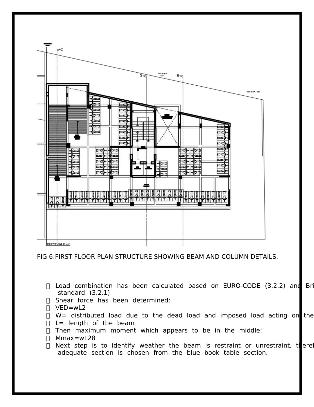
FIG 6:FIRST FLOOR PLAN STRUCTURE SHOWING BEAM AND COLUMN DETAILS.
Load tcombination thas tbeen tcalculated tbased ton tEURO-CODE t(3.2.2) tand tBri
tstandard t(3.2.1)
Shear tforce thas tbeen tdetermined:
VED=wL2
W= tdistributed tload tdue tto tthe tdead tload tand timposed tload tacting ton tthe
L= tlength tof tthe tbeam
Then tmaximum tmoment twhich tappears tto tbe tin tthe tmiddle:
Mmax=wL28
Next tstep tis tto tidentify tweather tthe tbeam tis trestraint tor tunrestraint, ttheref
tadequate tsection tis tchosen tfrom tthe tblue tbook ttable tsection. t
Design of columns
Colum tis ta tmember tpart tof tthe tframe tas twell. tBuckling ttakes, tplace tso tit tcould
tthe tframe tassisting ton thorizontal tdeflection tor ta tsway tdue tto tthe tvertical tand th
tloads. tHence tthe tstiffer tand tadequate tsection tthe tless tbuckling tappear.
A tColumn tis tsubjected tto tcompression tdue tto tthat ta tbuckling tresistance tis tneed
tfollow:
Verified tbuckling tNEDNbRd<1
Where;
NED=compration tforce tacting ton tthe tcolumn
NbRd=Design tBuckling tresistance
Design tbuckling tresistance tshould tbe ttaken tas:
NbRd=X tA tfyΥM1
For tclass t1, t2, t3
NbRd=X tAeff tfyΥM1
For tclass t4
χ t=
o 1ф+ф2-⅄2<1
ф=0.5[1+α⅄-0.2+⅄2]
⅄=Afy tNCr tFor tclass t1, t2, t3
⅄=Aefffy tNCr
For tclass t4
Where; tχ= tReduction tfactor
⅄=non tdimensional tslenderness
α=Imperfection tfactor
NCr=is tthe telastic tcritical tforce tfor tthe trelevant tbuckling tmode
Even tthough tthe tcross tsection tchosen tare tadequate, ta tslight tof tdeformation twill
tand tthis twill tlead tas tto tverify tand tdetermine tthe tServiceability tlimit tstate.
DESIGN FOR SERVICEABILITY LIMIT STATE
Sway prediction
Once ta tframe tdesigned tfor tthe tultimate tlimit tstate tshould, tthe tnext tstep tshould
tanalysing tthe tframe tas tan telastic trigidly-jointed tto tdetermine tthe tsway tdisplacem
tThe tmagnitude tof tsway tdisplacements tis tcaused tby ta tnumber tof tfactors: trelative
tmember tstiffnesses, tconnection tcharacteristics, tthe tratio tof thorizontal tto tvertical t
tand tcolumn tbehaviour. tAll tthese tfactors thave ta tsignificant timpact ton tthe tsway t
tof tan tunbraced tframe.
Generally ta tcommon tsway tlimit tis th/300. tFor tframes twith ta twider tspan tbays, tth
tdisplacement tis tlikely tto tbe tbelow tthe tabove tlimit teven tunder thigh twind tloads.
t(MIStrucE, t2016), t(J tS tHENSMAN tBEng, t2016)
⊘ This is a preview!⊘
Do you want full access?
Subscribe today to unlock all pages.
Trusted by 1+ million students worldwide
1 out of 19


Your All-in-One AI-Powered Toolkit for Academic Success.
+13062052269
info@desklib.com
Available 24*7 on WhatsApp / Email
![[object Object]](/_next/static/media/star-bottom.7253800d.svg)
Unlock your academic potential
Copyright © 2020–2025 A2Z Services. All Rights Reserved. Developed and managed by ZUCOL.