Facade Design Project: Wind Load, Glass, Mullion, and Skylight Design
VerifiedAdded on 2023/03/30
|9
|1080
|248
Project
AI Summary
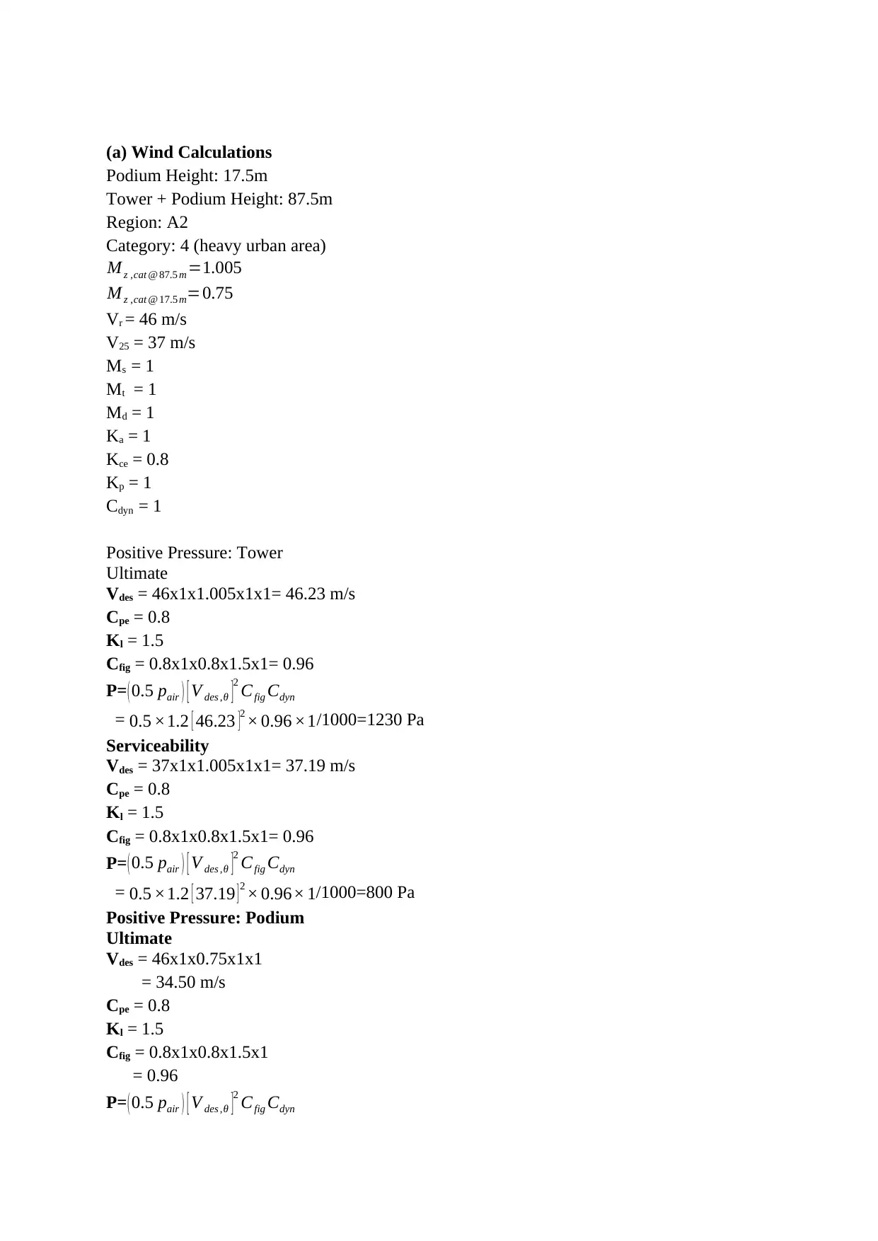
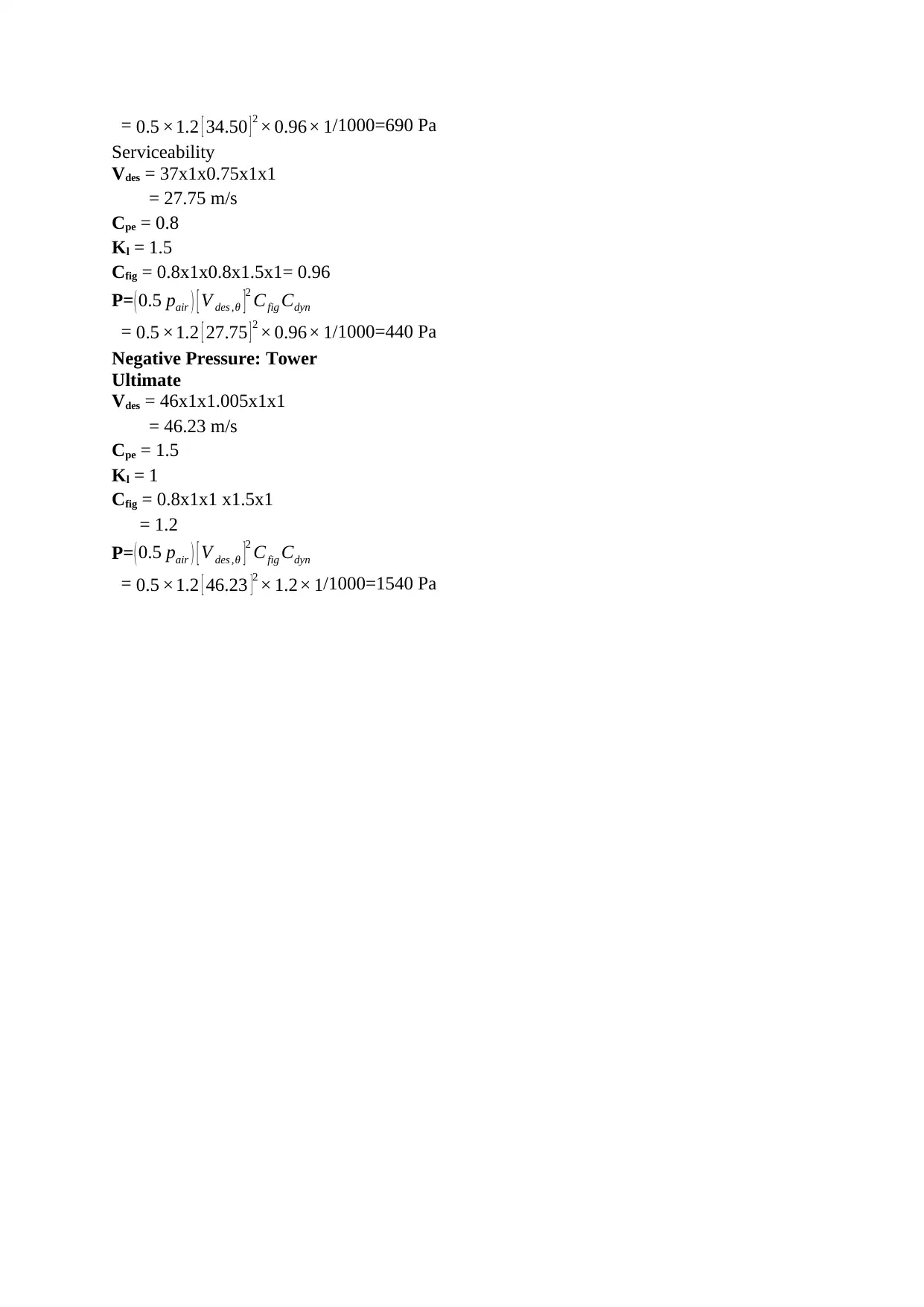
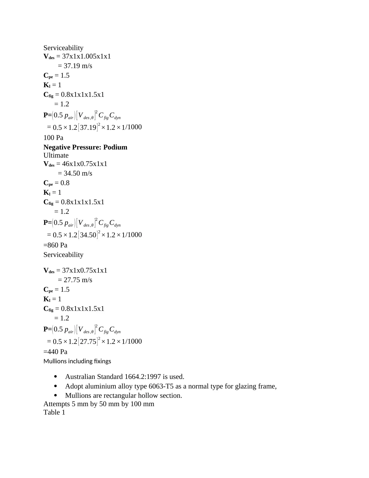
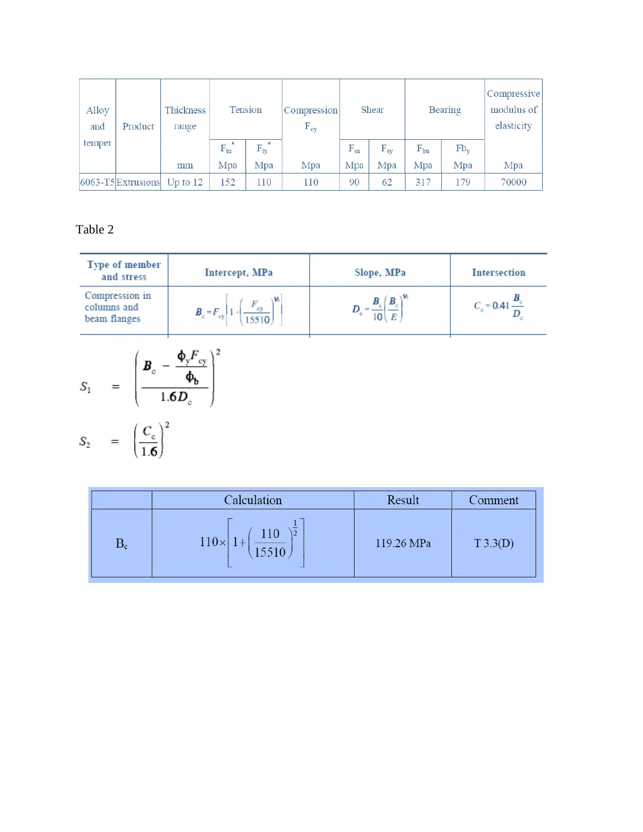
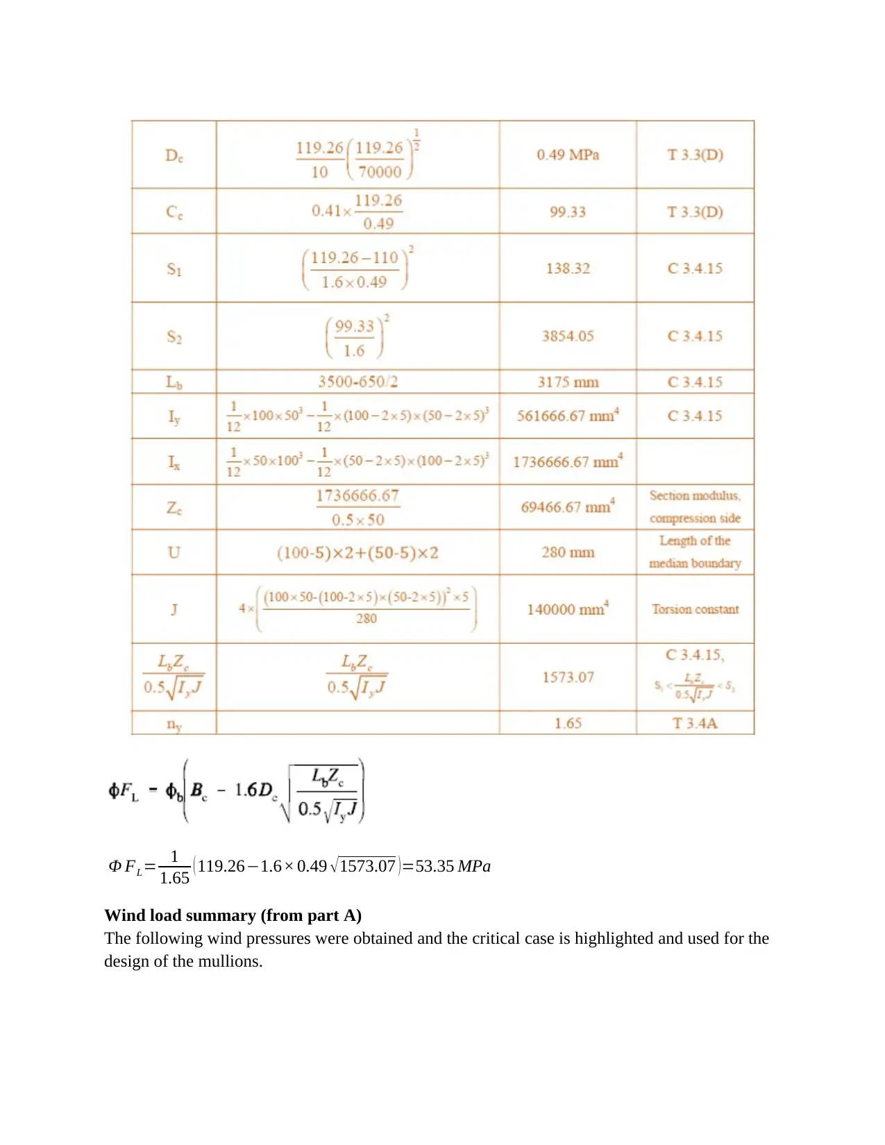
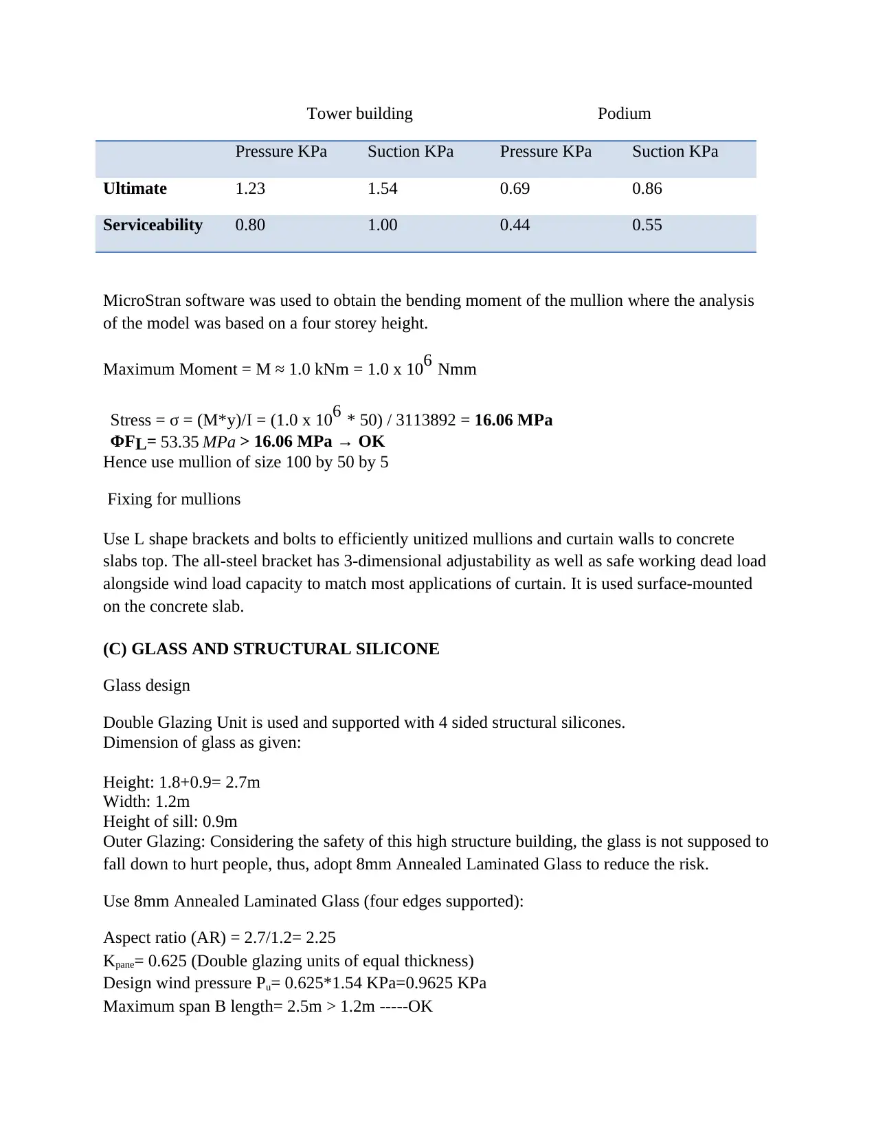
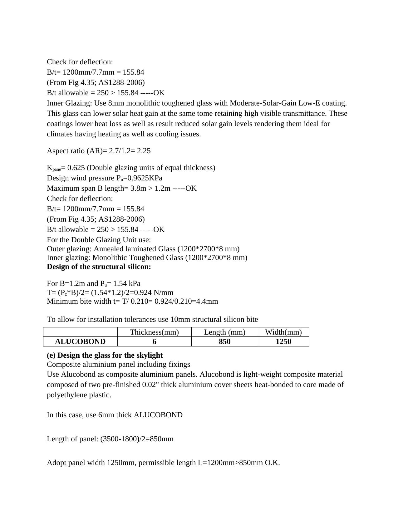
This assignment presents a comprehensive facade design solution for a hospital building in Sydney, Australia. It begins with wind load calculations for both the tower and podium, considering ultimate and serviceability limit states, and determining design wind pressures. The design then moves to the selection and analysis of mullions, including the application of Australian Standard 1664.2:1997, stress calculations, and fixing details using L-shaped brackets and bolts. Following this, the design of the glass components is detailed, specifying double glazing units with 8mm annealed laminated glass for outer glazing and 8mm monolithic toughened glass with a Low-E coating for inner glazing, along with deflection checks and structural silicone design. Finally, the design incorporates Alucobond composite aluminium panels for the skylight, specifying panel dimensions and permissible lengths. The solution adheres to relevant Australian standards and provides detailed calculations and specifications for each component of the facade system.

FAÇADE DESIGN
By Name
Course
Instructor
Institution
Location
Date
By Name
Course
Instructor
Institution
Location
Date
Paraphrase This Document
Need a fresh take? Get an instant paraphrase of this document with our AI Paraphraser

(a) Wind Calculations
Podium Height: 17.5m
Tower + Podium Height: 87.5m
Region: A2
Category: 4 (heavy urban area)
M z ,cat @ 87.5 m =1.005
M z ,cat @ 17.5 m=0.75
Vr = 46 m/s
V25 = 37 m/s
Ms = 1
Mt = 1
Md = 1
Ka = 1
Kce = 0.8
Kp = 1
Cdyn = 1
Positive Pressure: Tower
Ultimate
Vdes = 46x1x1.005x1x1= 46.23 m/s
Cpe = 0.8
Kl = 1.5
Cfig = 0.8x1x0.8x1.5x1= 0.96
P=( 0.5 pair ) [ V des ,θ ]2 Cfig Cdyn
= 0.5 ×1.2 [ 46.23 ]
2 × 0.96 ×1/1000=1230 Pa
Serviceability
Vdes = 37x1x1.005x1x1= 37.19 m/s
Cpe = 0.8
Kl = 1.5
Cfig = 0.8x1x0.8x1.5x1= 0.96
P=( 0.5 pair ) [ V des ,θ ]2 Cfig Cdyn
= 0.5 ×1.2 [ 37.19 ] 2 × 0.96× 1/1000=800 Pa
Positive Pressure: Podium
Ultimate
Vdes = 46x1x0.75x1x1
= 34.50 m/s
Cpe = 0.8
Kl = 1.5
Cfig = 0.8x1x0.8x1.5x1
= 0.96
P=( 0.5 pair ) [ V des ,θ ]2 Cfig Cdyn

= 0.5 ×1.2 [ 34.50 ] 2 × 0.96× 1/1000=690 Pa
Serviceability
Vdes = 37x1x0.75x1x1
= 27.75 m/s
Cpe = 0.8
Kl = 1.5
Cfig = 0.8x1x0.8x1.5x1= 0.96
P=( 0.5 pair ) [ V des ,θ ]2 Cfig Cdyn
= 0.5 ×1.2 [ 27.75 ] 2 × 0.96× 1/1000=440 Pa
Negative Pressure: Tower
Ultimate
Vdes = 46x1x1.005x1x1
= 46.23 m/s
Cpe = 1.5
Kl = 1
Cfig = 0.8x1x1 x1.5x1
= 1.2
P=( 0.5 pair ) [ V des ,θ ]2 Cfig Cdyn
= 0.5 ×1.2 [ 46.23 ]2 × 1.2× 1/1000=1540 Pa
⊘ This is a preview!⊘
Do you want full access?
Subscribe today to unlock all pages.

Trusted by 1+ million students worldwide

Serviceability
Vdes = 37x1x1.005x1x1
= 37.19 m/s
Cpe = 1.5
Kl = 1
Cfig = 0.8x1x1x1.5x1
= 1.2
P=( 0.5 pair ) [ V des ,θ ]2 Cfig Cdyn
= 0.5 ×1.2 [ 37.19 ] 2 ×1.2 ×1/1000
100 Pa
Negative Pressure: Podium
Ultimate
Vdes = 46x1x0.75x1x1
= 34.50 m/s
Cpe = 0.8
Kl = 1
Cfig = 0.8x1x1x1.5x1
= 1.2
P=( 0.5 pair ) [ V des ,θ ]2 Cfig Cdyn
= 0.5 ×1.2 [ 34.50 ] 2 ×1.2 ×1/1000
=860 Pa
Serviceability
Vdes = 37x1x0.75x1x1
= 27.75 m/s
Cpe = 1.5
Kl = 1
Cfig = 0.8x1x1x1.5x1
= 1.2
P=( 0.5 pair ) [ V des ,θ ]2 Cfig Cdyn
= 0.5 ×1.2 [ 27.75 ] 2 ×1.2 ×1/1000
=440 Pa
Mullions including fixings
Australian Standard 1664.2:1997 is used.
Adopt aluminium alloy type 6063-T5 as a normal type for glazing frame,
Mullions are rectangular hollow section.
Attempts 5 mm by 50 mm by 100 mm
Table 1
Paraphrase This Document
Need a fresh take? Get an instant paraphrase of this document with our AI Paraphraser

Table 2

Φ FL= 1
1.65 ( 119.26−1.6× 0.49 √1573.07 )=53.35 MPa
Wind load summary (from part A)
The following wind pressures were obtained and the critical case is highlighted and used for the
design of the mullions.
1.65 ( 119.26−1.6× 0.49 √1573.07 )=53.35 MPa
Wind load summary (from part A)
The following wind pressures were obtained and the critical case is highlighted and used for the
design of the mullions.
⊘ This is a preview!⊘
Do you want full access?
Subscribe today to unlock all pages.

Trusted by 1+ million students worldwide

Tower building Podium
Pressure KPa Suction KPa Pressure KPa Suction KPa
Ultimate 1.23 1.54 0.69 0.86
Serviceability 0.80 1.00 0.44 0.55
MicroStran software was used to obtain the bending moment of the mullion where the analysis
of the model was based on a four storey height.
Maximum Moment = M ≈ 1.0 kNm = 1.0 x 10⁶ Nmm
Stress = σ = (M*y)/I = (1.0 x 106 * 50) / 3113892 = 16.06 MPa
ΦFL= 53.35 MPa > 16.06 MPa → OK
Hence use mullion of size 100 by 50 by 5
Fixing for mullions
Use L shape brackets and bolts to efficiently unitized mullions and curtain walls to concrete
slabs top. The all-steel bracket has 3-dimensional adjustability as well as safe working dead load
alongside wind load capacity to match most applications of curtain. It is used surface-mounted
on the concrete slab.
(C) GLASS AND STRUCTURAL SILICONE
Glass design
Double Glazing Unit is used and supported with 4 sided structural silicones.
Dimension of glass as given:
Height: 1.8+0.9= 2.7m
Width: 1.2m
Height of sill: 0.9m
Outer Glazing: Considering the safety of this high structure building, the glass is not supposed to
fall down to hurt people, thus, adopt 8mm Annealed Laminated Glass to reduce the risk.
Use 8mm Annealed Laminated Glass (four edges supported):
Aspect ratio (AR) = 2.7/1.2= 2.25
Kpane= 0.625 (Double glazing units of equal thickness)
Design wind pressure Pu= 0.625*1.54 KPa=0.9625 KPa
Maximum span B length= 2.5m > 1.2m -----OK
Paraphrase This Document
Need a fresh take? Get an instant paraphrase of this document with our AI Paraphraser

Check for deflection:
B/t= 1200mm/7.7mm = 155.84
(From Fig 4.35; AS1288-2006)
B/t allowable = 250 > 155.84 -----OK
Inner Glazing: Use 8mm monolithic toughened glass with Moderate-Solar-Gain Low-E coating.
This glass can lower solar heat gain at the same tome retaining high visible transmittance. These
coatings lower heat loss as well as result reduced solar gain levels rendering them ideal for
climates having heating as well as cooling issues.
Aspect ratio (AR)= 2.7/1.2= 2.25
Kpane= 0.625 (Double glazing units of equal thickness)
Design wind pressure Pu=0.9625KPa
Maximum span B length= 3.8m > 1.2m -----OK
Check for deflection:
B/t= 1200mm/7.7mm = 155.84
(From Fig 4.35; AS1288-2006)
B/t allowable = 250 > 155.84 -----OK
For the Double Glazing Unit use:
Outer glazing: Annealed laminated Glass (1200*2700*8 mm)
Inner glazing: Monolithic Toughened Glass (1200*2700*8 mm)
Design of the structural silicon:
For B=1.2m and Pu= 1.54 kPa
T= (Pz*B)/2= (1.54*1.2)/2=0.924 N/mm
Minimum bite width t= T/ 0.210= 0.924/0.210=4.4mm
To allow for installation tolerances use 10mm structural silicon bite
(e) Design the glass for the skylight
Composite aluminium panel including fixings
Use Alucobond as composite aluminium panels. Alucobond is light-weight composite material
composed of two pre-finished 0.02" thick aluminium cover sheets heat-bonded to core made of
polyethylene plastic.
In this case, use 6mm thick ALUCOBOND
Length of panel: (3500-1800)/2=850mm
Adopt panel width 1250mm, permissible length L=1200mm>850mm O.K.
Thickness(mm) Length (mm) Width(mm)
ALUCOBOND 6 850 1250
B/t= 1200mm/7.7mm = 155.84
(From Fig 4.35; AS1288-2006)
B/t allowable = 250 > 155.84 -----OK
Inner Glazing: Use 8mm monolithic toughened glass with Moderate-Solar-Gain Low-E coating.
This glass can lower solar heat gain at the same tome retaining high visible transmittance. These
coatings lower heat loss as well as result reduced solar gain levels rendering them ideal for
climates having heating as well as cooling issues.
Aspect ratio (AR)= 2.7/1.2= 2.25
Kpane= 0.625 (Double glazing units of equal thickness)
Design wind pressure Pu=0.9625KPa
Maximum span B length= 3.8m > 1.2m -----OK
Check for deflection:
B/t= 1200mm/7.7mm = 155.84
(From Fig 4.35; AS1288-2006)
B/t allowable = 250 > 155.84 -----OK
For the Double Glazing Unit use:
Outer glazing: Annealed laminated Glass (1200*2700*8 mm)
Inner glazing: Monolithic Toughened Glass (1200*2700*8 mm)
Design of the structural silicon:
For B=1.2m and Pu= 1.54 kPa
T= (Pz*B)/2= (1.54*1.2)/2=0.924 N/mm
Minimum bite width t= T/ 0.210= 0.924/0.210=4.4mm
To allow for installation tolerances use 10mm structural silicon bite
(e) Design the glass for the skylight
Composite aluminium panel including fixings
Use Alucobond as composite aluminium panels. Alucobond is light-weight composite material
composed of two pre-finished 0.02" thick aluminium cover sheets heat-bonded to core made of
polyethylene plastic.
In this case, use 6mm thick ALUCOBOND
Length of panel: (3500-1800)/2=850mm
Adopt panel width 1250mm, permissible length L=1200mm>850mm O.K.
Thickness(mm) Length (mm) Width(mm)
ALUCOBOND 6 850 1250

References
Hachem, C. and Elsayed, M., 2016. Patterns of façade system design for enhanced energy
performance of multistory buildings. Energy and Buildings, 130, pp.366-377
Loonen, R.C.G.M., Rico-Martinez, J.M., Favoino, F., Brzezicki, M., Menezo, C., La Ferla, G.
and Aelenei, L., 2015, November. Design for façade adaptability–Towards a unified and
systematic characterization. In Proceedings of the 10th Energy Forum-Advanced Building Skins.
Bern, Switzerland(pp. 1274-1284)
Othman, A.R. and Sahidin, N., 2016. Vertical greening façade as passive approach in sustainable
design. Procedia-Social and Behavioral Sciences, 222, pp.845-854
Vanhoutteghem, L., Skarning, G.C.J., Hviid, C.A. and Svendsen, S., 2015. Impact of façade
window design on energy, daylighting and thermal comfort in nearly zero-energy houses. Energy
and Buildings, 102, pp.149-156
⊘ This is a preview!⊘
Do you want full access?
Subscribe today to unlock all pages.

Trusted by 1+ million students worldwide
1 out of 9
Your All-in-One AI-Powered Toolkit for Academic Success.
+13062052269
info@desklib.com
Available 24*7 on WhatsApp / Email
Unlock your academic potential
Copyright © 2020–2026 A2Z Services. All Rights Reserved. Developed and managed by ZUCOL.

