Installation and Verification Protocol for Hot Detergent System
VerifiedAdded on 2020/04/15
|85
|13776
|199
Project
AI Summary
This document presents an Installation and Functional Verification Protocol for a Hot Detergent and Hot Purified Water (PUW) Generation and Distribution System. The protocol aims to provide evidence that the system is fit for its intended use, incorporating both installation and functional verification tests. It includes a detailed system description, scope assessment (including system and component impact assessments), and a summary table of operational critical components. The document outlines testing procedures for P&ID walkdowns, equipment installation, instrument installation, and piping installation, along with calibration and preventative maintenance program verifications. Functional verification procedures cover detergent dosing, temperature, flow, and level controls for both hot detergent and hot PUW systems. The protocol also details quality procedures, including signature logs, deviation procedures, and change control procedures, and provides comprehensive appendices with GMP checksheets, deviation logs, and component impact assessments to ensure the system's safe and effective operation within a pharmaceutical manufacturing context. This document is a valuable resource for students seeking to understand the complexities of process validation and quality assurance in environmental engineering and pharmaceutical manufacturing.
1 Title Page
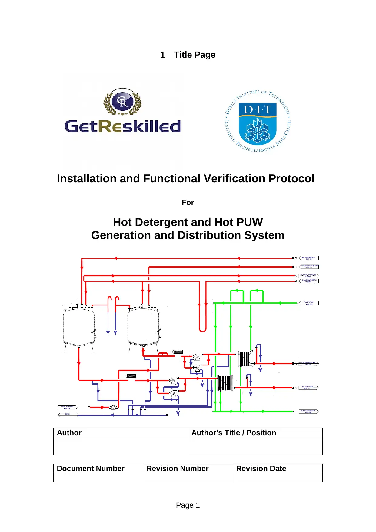
Installation and Functional Verification Protocol
For
Hot Detergent and Hot PUW
Generation and Distribution System
Author Author’s Title / Position
Document Number Revision Number Revision Date
Page 1
Installation and Functional Verification Protocol
For
Hot Detergent and Hot PUW
Generation and Distribution System
Author Author’s Title / Position
Document Number Revision Number Revision Date
Page 1
Paraphrase This Document
Need a fresh take? Get an instant paraphrase of this document with our AI Paraphraser
Page 2
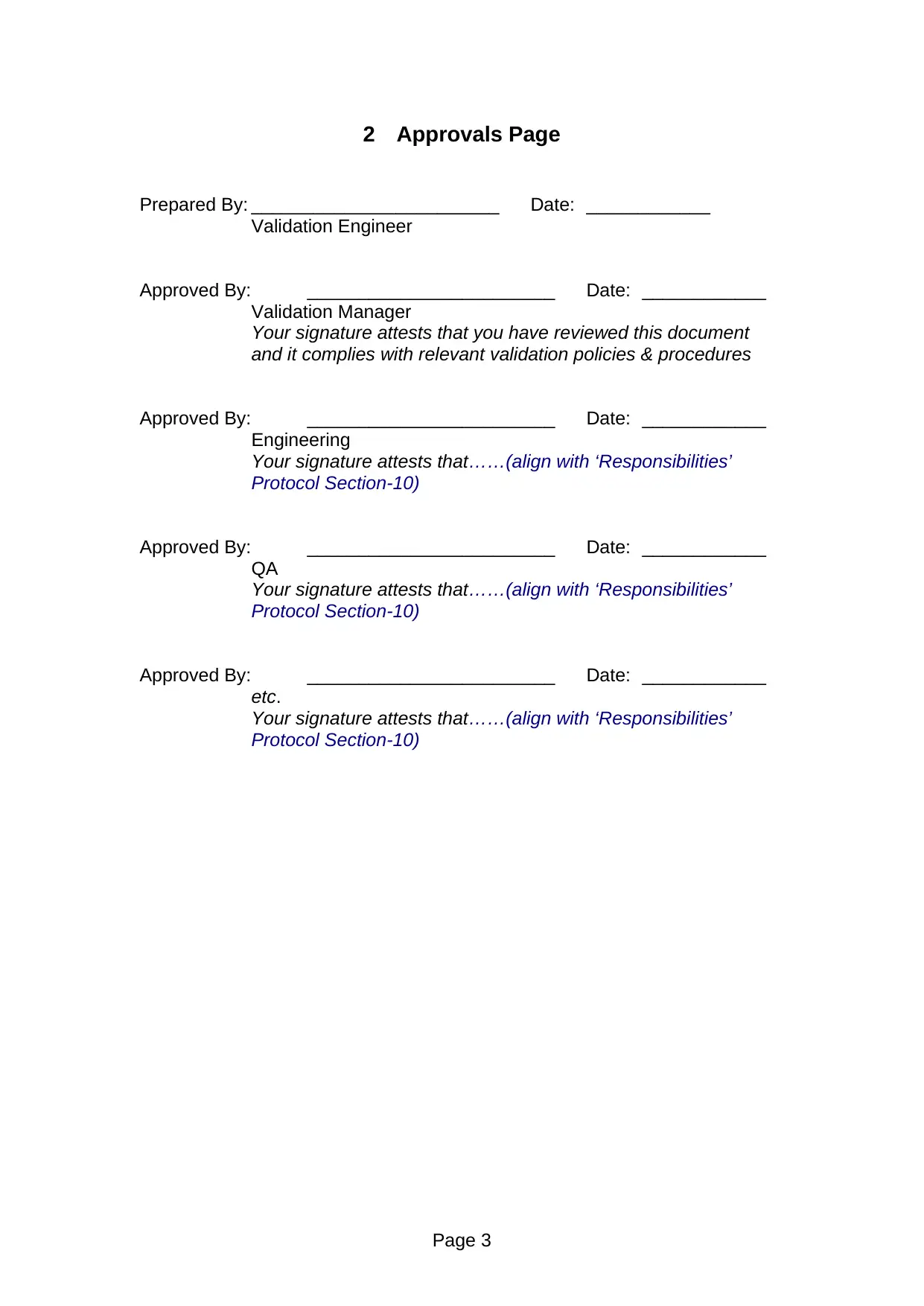
2 Approvals Page
Prepared By: ________________________ Date: ____________
Validation Engineer
Approved By: ________________________ Date: ____________
Validation Manager
Your signature attests that you have reviewed this document
and it complies with relevant validation policies & procedures
Approved By: ________________________ Date: ____________
Engineering
Your signature attests that……(align with ‘Responsibilities’
Protocol Section-10)
Approved By: ________________________ Date: ____________
QA
Your signature attests that……(align with ‘Responsibilities’
Protocol Section-10)
Approved By: ________________________ Date: ____________
etc.
Your signature attests that……(align with ‘Responsibilities’
Protocol Section-10)
Page 3
⊘ This is a preview!⊘
Do you want full access?
Subscribe today to unlock all pages.
Trusted by 1+ million students worldwide
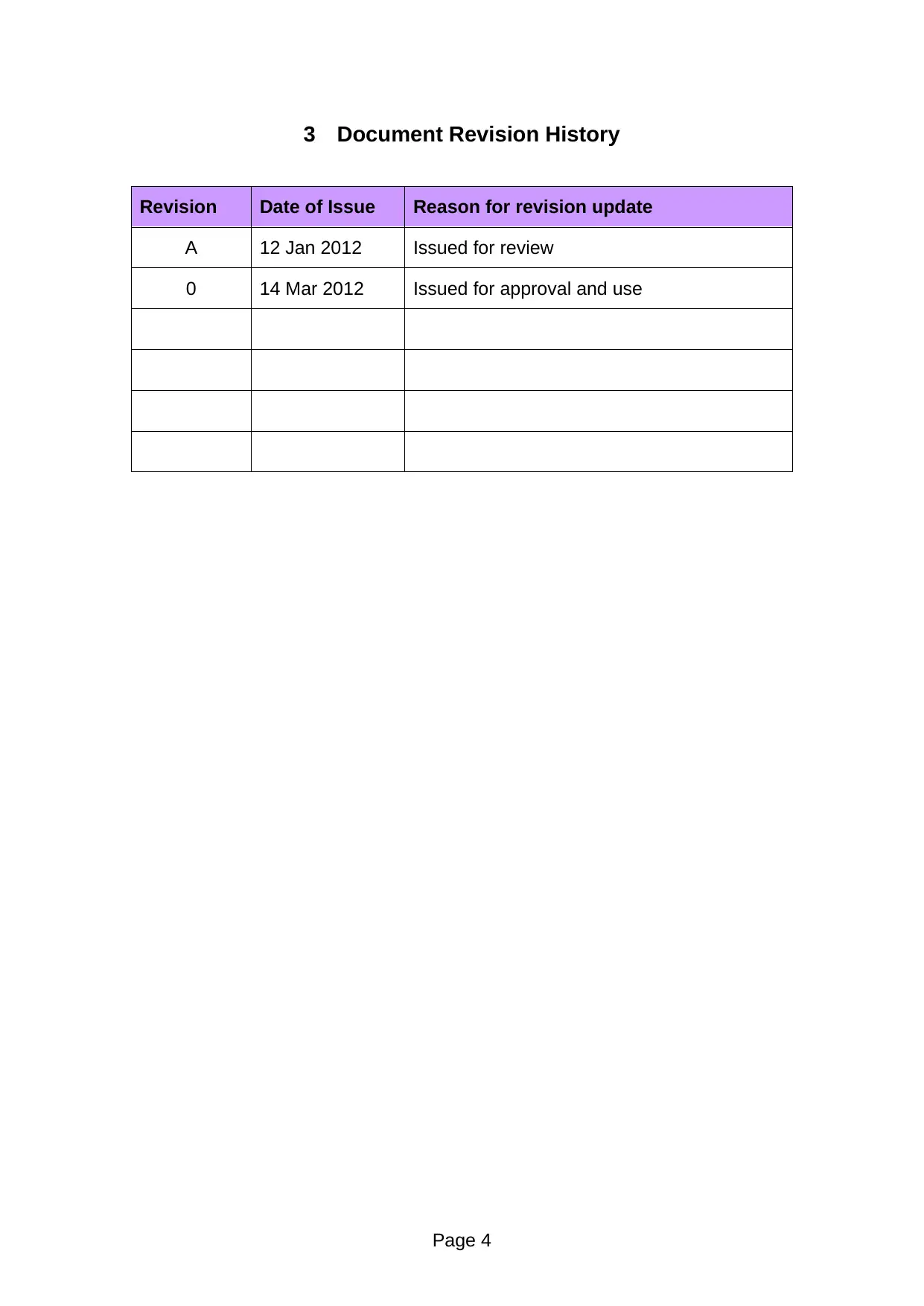
3 Document Revision History
Revision Date of Issue Reason for revision update
A 12 Jan 2012 Issued for review
0 14 Mar 2012 Issued for approval and use
Page 4
Revision Date of Issue Reason for revision update
A 12 Jan 2012 Issued for review
0 14 Mar 2012 Issued for approval and use
Page 4
Paraphrase This Document
Need a fresh take? Get an instant paraphrase of this document with our AI Paraphraser
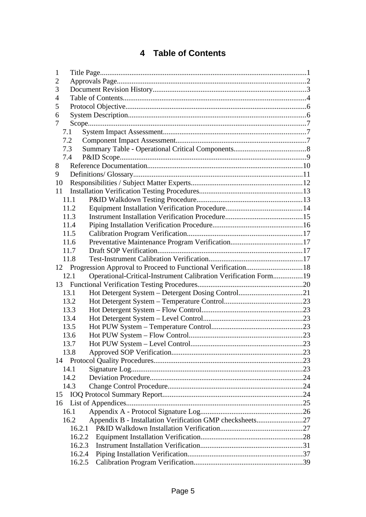
4 Table of Contents
1 Title Page................................................................................................................1
2 Approvals Page......................................................................................................2
3 Document Revision History...................................................................................3
4 Table of Contents...................................................................................................4
5 Protocol Objective..................................................................................................6
6 System Description................................................................................................6
7 Scope......................................................................................................................7
7.1 System Impact Assessment.............................................................................7
7.2 Component Impact Assessment.......................................................................7
7.3 Summary Table - Operational Critical Components.......................................8
7.4 P&ID Scope.....................................................................................................9
8 Reference Documentation....................................................................................10
9 Definitions/ Glossary............................................................................................11
10 Responsibilities / Subject Matter Experts............................................................12
11 Installation Verification Testing Procedures........................................................13
11.1 P&ID Walkdown Testing Procedure.........................................................13
11.2 Equipment Installation Verification Procedure.........................................14
11.3 Instrument Installation Verification Procedure..........................................15
11.4 Piping Installation Verification Procedure.................................................16
11.5 Calibration Program Verification..............................................................17
11.6 Preventative Maintenance Program Verification.......................................17
11.7 Draft SOP Verification..............................................................................17
11.8 Test-Instrument Calibration Verification...................................................17
12 Progression Approval to Proceed to Functional Verification..............................18
12.1 Operational-Critical-Instrument Calibration Verification Form................19
13 Functional Verification Testing Procedures.........................................................20
13.1 Hot Detergent System – Detergent Dosing Control..................................21
13.2 Hot Detergent System – Temperature Control..........................................23
13.3 Hot Detergent System – Flow Control.......................................................23
13.4 Hot Detergent System – Level Control......................................................23
13.5 Hot PUW System – Temperature Control.................................................23
13.6 Hot PUW System – Flow Control.............................................................23
13.7 Hot PUW System – Level Control.............................................................23
13.8 Approved SOP Verification.......................................................................23
14 Protocol Quality Procedures.................................................................................23
14.1 Signature Log.............................................................................................23
14.2 Deviation Procedure...................................................................................24
14.3 Change Control Procedure.........................................................................24
15 IOQ Protocol Summary Report............................................................................24
16 List of Appendices...............................................................................................25
16.1 Appendix A - Protocol Signature Log.......................................................26
16.2 Appendix B - Installation Verification GMP checksheets.........................27
16.2.1 P&ID Walkdown Installation Verification............................................27
16.2.2 Equipment Installation Verification.......................................................28
16.2.3 Instrument Installation Verification.......................................................31
16.2.4 Piping Installation Verification..............................................................37
16.2.5 Calibration Program Verification...........................................................39
Page 5
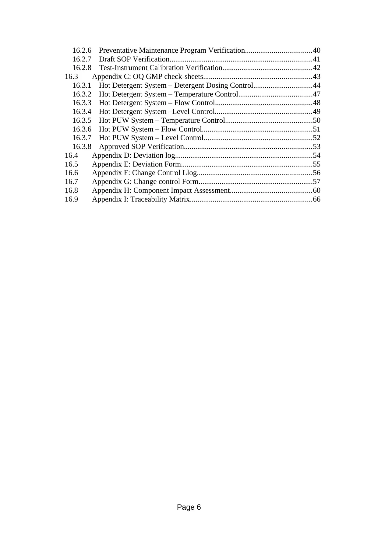
16.2.6 Preventative Maintenance Program Verification...................................40
16.2.7 Draft SOP Verification...........................................................................41
16.2.8 Test-Instrument Calibration Verification...............................................42
16.3 Appendix C: OQ GMP check-sheets.........................................................43
16.3.1 Hot Detergent System – Detergent Dosing Control...............................44
16.3.2 Hot Detergent System – Temperature Control.......................................47
16.3.3 Hot Detergent System – Flow Control...................................................48
16.3.4 Hot Detergent System –Level Control...................................................49
16.3.5 Hot PUW System – Temperature Control..............................................50
16.3.6 Hot PUW System – Flow Control..........................................................51
16.3.7 Hot PUW System – Level Control.........................................................52
16.3.8 Approved SOP Verification...................................................................53
16.4 Appendix D: Deviation log........................................................................54
16.5 Appendix E: Deviation Form.....................................................................55
16.6 Appendix F: Change Control Llog............................................................56
16.7 Appendix G: Change control Form............................................................57
16.8 Appendix H: Component Impact Assessment...........................................60
16.9 Appendix I: Traceability Matrix................................................................66
Page 6
⊘ This is a preview!⊘
Do you want full access?
Subscribe today to unlock all pages.
Trusted by 1+ million students worldwide
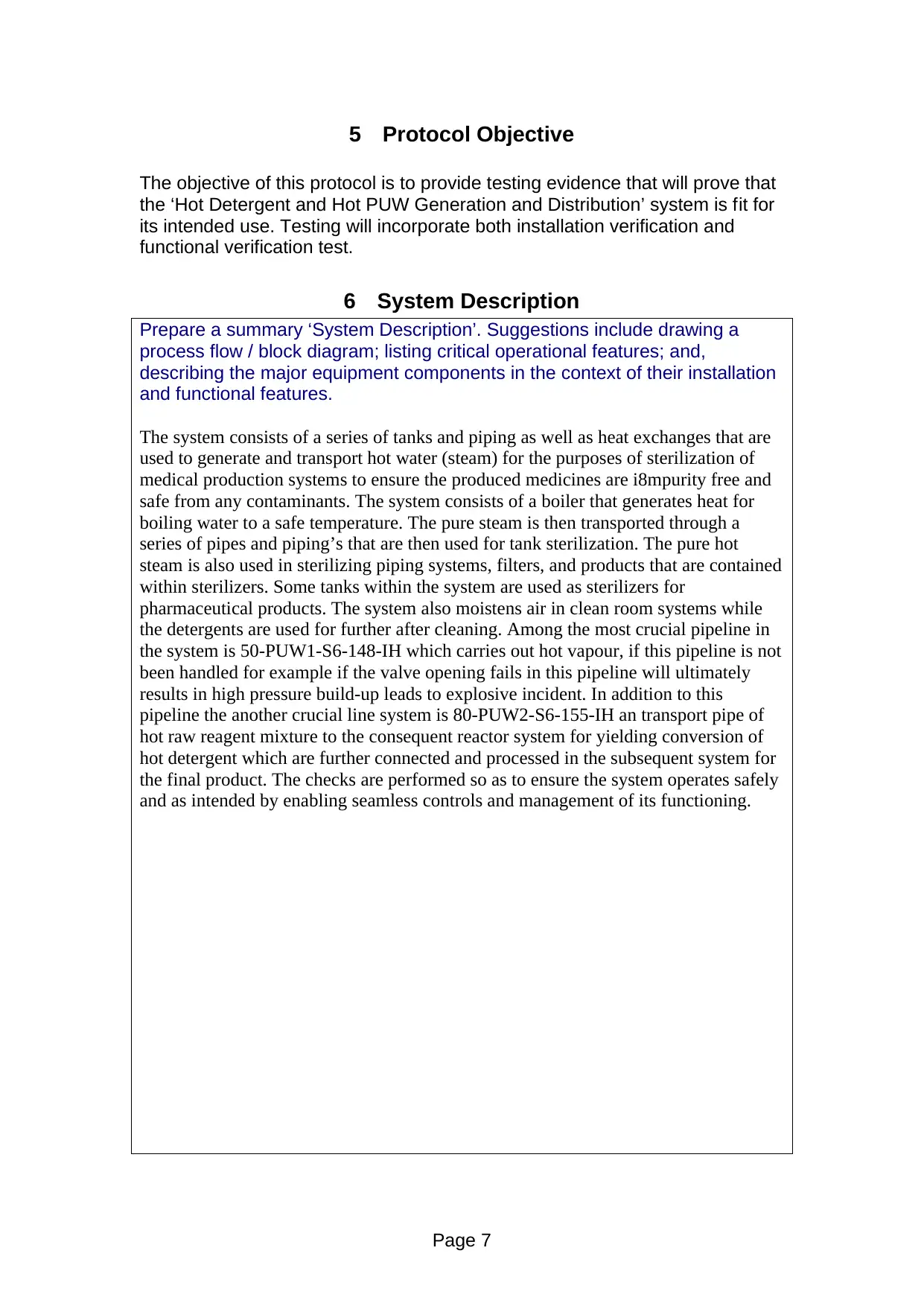
5 Protocol Objective
The objective of this protocol is to provide testing evidence that will prove that
the ‘Hot Detergent and Hot PUW Generation and Distribution’ system is fit for
its intended use. Testing will incorporate both installation verification and
functional verification test.
6 System Description
Prepare a summary ‘System Description’. Suggestions include drawing a
process flow / block diagram; listing critical operational features; and,
describing the major equipment components in the context of their installation
and functional features.
The system consists of a series of tanks and piping as well as heat exchanges that are
used to generate and transport hot water (steam) for the purposes of sterilization of
medical production systems to ensure the produced medicines are i8mpurity free and
safe from any contaminants. The system consists of a boiler that generates heat for
boiling water to a safe temperature. The pure steam is then transported through a
series of pipes and piping’s that are then used for tank sterilization. The pure hot
steam is also used in sterilizing piping systems, filters, and products that are contained
within sterilizers. Some tanks within the system are used as sterilizers for
pharmaceutical products. The system also moistens air in clean room systems while
the detergents are used for further after cleaning. Among the most crucial pipeline in
the system is 50-PUW1-S6-148-IH which carries out hot vapour, if this pipeline is not
been handled for example if the valve opening fails in this pipeline will ultimately
results in high pressure build-up leads to explosive incident. In addition to this
pipeline the another crucial line system is 80-PUW2-S6-155-IH an transport pipe of
hot raw reagent mixture to the consequent reactor system for yielding conversion of
hot detergent which are further connected and processed in the subsequent system for
the final product. The checks are performed so as to ensure the system operates safely
and as intended by enabling seamless controls and management of its functioning.
Page 7
Paraphrase This Document
Need a fresh take? Get an instant paraphrase of this document with our AI Paraphraser
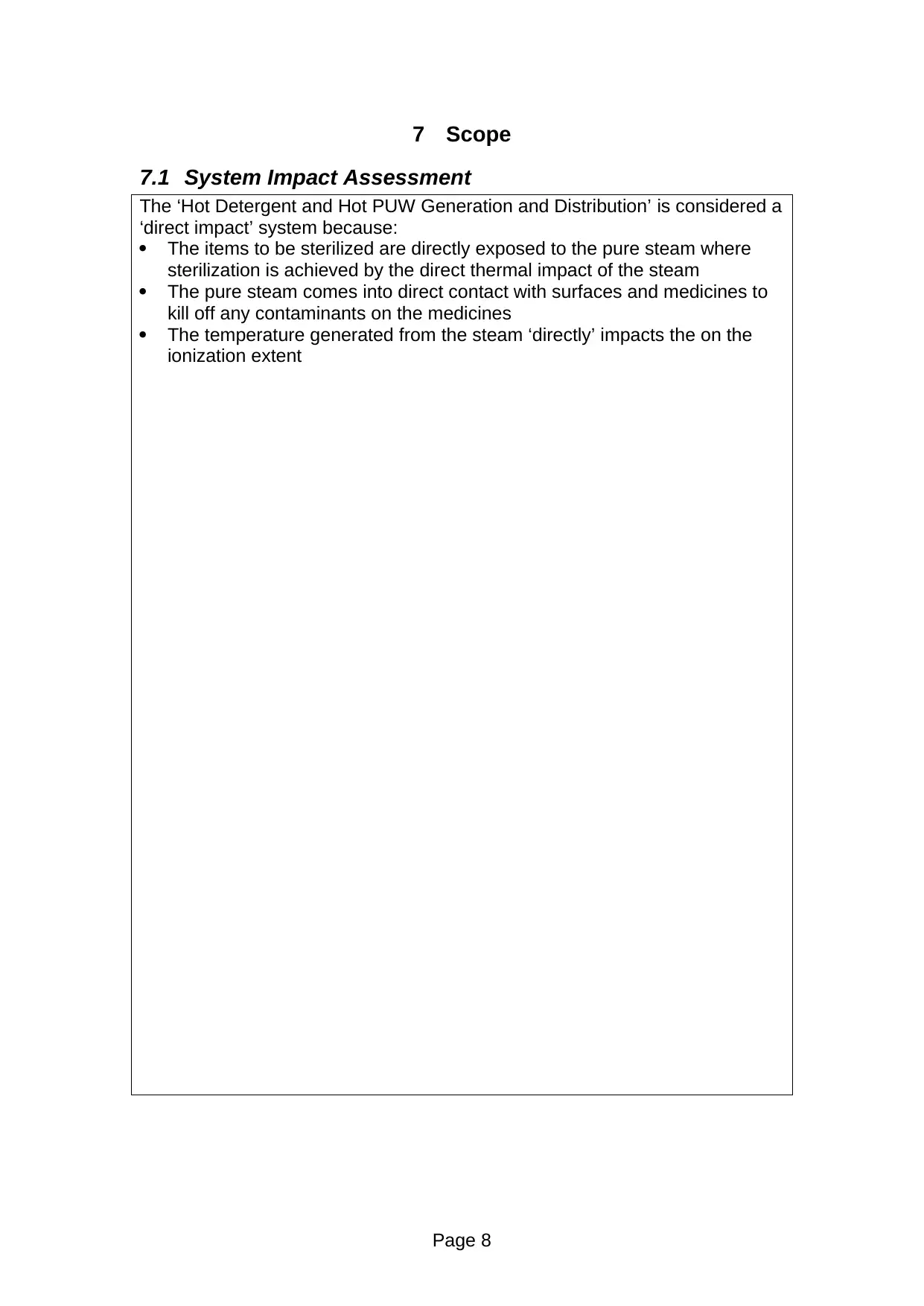
7 Scope
7.1 System Impact Assessment
The ‘Hot Detergent and Hot PUW Generation and Distribution’ is considered a
‘direct impact’ system because:
The items to be sterilized are directly exposed to the pure steam where
sterilization is achieved by the direct thermal impact of the steam
The pure steam comes into direct contact with surfaces and medicines to
kill off any contaminants on the medicines
The temperature generated from the steam ‘directly’ impacts the on the
ionization extent
Page 8
7.2 Component Impact Assessment
The Component Impact Assessment will drive the scope of the installation and
functional verifications. Product contact plus operational critical components
must be included in the installation verifications. The operationally critical
components will drive the functionality testing.
Page 9
The Component Impact Assessment will drive the scope of the installation and
functional verifications. Product contact plus operational critical components
must be included in the installation verifications. The operationally critical
components will drive the functionality testing.
Page 9
⊘ This is a preview!⊘
Do you want full access?
Subscribe today to unlock all pages.
Trusted by 1+ million students worldwide
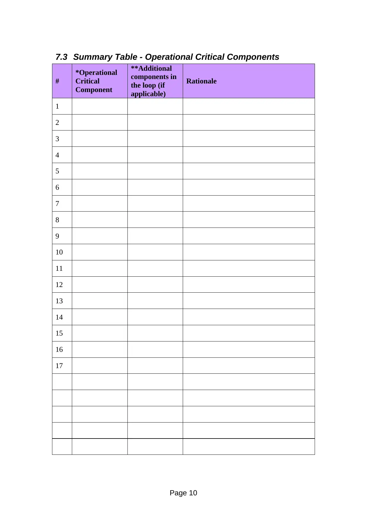
7.3 Summary Table - Operational Critical Components
#
*Operational
Critical
Component
**Additional
components in
the loop (if
applicable)
Rationale
1
2
3
4
5
6
7
8
9
10
11
12
13
14
15
16
17
Page 10
#
*Operational
Critical
Component
**Additional
components in
the loop (if
applicable)
Rationale
1
2
3
4
5
6
7
8
9
10
11
12
13
14
15
16
17
Page 10
Paraphrase This Document
Need a fresh take? Get an instant paraphrase of this document with our AI Paraphraser
7.4 P&ID Scope
In Protocol Section-7.4 include a copy/scan of the P&ID and either draw a
‘scope bubble’ or yellow-highlight the ‘in-scope’ components.
Page 11
In Protocol Section-7.4 include a copy/scan of the P&ID and either draw a
‘scope bubble’ or yellow-highlight the ‘in-scope’ components.
Page 11
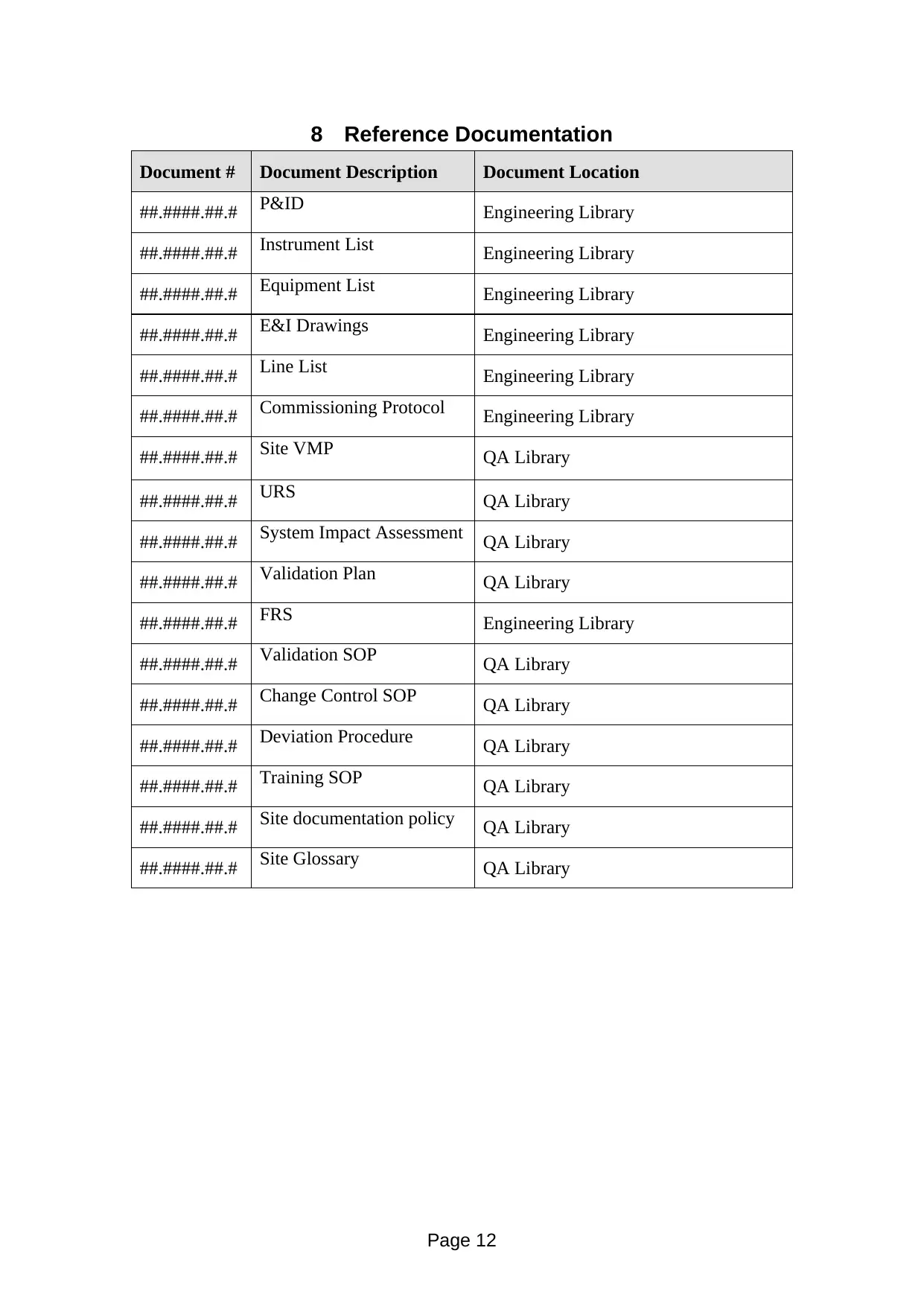
8 Reference Documentation
Document # Document Description Document Location
##.####.##.# P&ID Engineering Library
##.####.##.# Instrument List Engineering Library
##.####.##.# Equipment List Engineering Library
##.####.##.# E&I Drawings Engineering Library
##.####.##.# Line List Engineering Library
##.####.##.# Commissioning Protocol Engineering Library
##.####.##.# Site VMP QA Library
##.####.##.# URS QA Library
##.####.##.# System Impact Assessment QA Library
##.####.##.# Validation Plan QA Library
##.####.##.# FRS Engineering Library
##.####.##.# Validation SOP QA Library
##.####.##.# Change Control SOP QA Library
##.####.##.# Deviation Procedure QA Library
##.####.##.# Training SOP QA Library
##.####.##.# Site documentation policy QA Library
##.####.##.# Site Glossary QA Library
Page 12
⊘ This is a preview!⊘
Do you want full access?
Subscribe today to unlock all pages.
Trusted by 1+ million students worldwide
1 out of 85

Your All-in-One AI-Powered Toolkit for Academic Success.
+13062052269
info@desklib.com
Available 24*7 on WhatsApp / Email
![[object Object]](/_next/static/media/star-bottom.7253800d.svg)
Unlock your academic potential
Copyright © 2020–2026 A2Z Services. All Rights Reserved. Developed and managed by ZUCOL.