HVAC System Design Project: Brisbane Office, Semester 1, 2024
VerifiedAdded on 2023/03/23
|26
|7125
|45
Project
AI Summary
This HVAC assignment details the design of a system for a single-story office building in suburban Brisbane, addressing the requirements of the client, ActiveApp. The project includes calculating indoor and outdoor design conditions, determining zoned air-conditioned areas, and assessing building peak heat and cooling loads. The assignment covers internal heat loads from occupants, lighting, and equipment, as well as solar heat gain and loss through building components. Furthermore, it explores the selection of an appropriate air conditioning system and discusses sustainable HVAC system options, including energy-efficient active and passive approaches. The document also presents the project's abstract, table of contents, lists of figures and tables, and a bibliography.

Running head: HVAC ASSIGNMENT 1
HVAC Assignment
Firstname Lastname
Name of Institution
HVAC Assignment
Firstname Lastname
Name of Institution
Paraphrase This Document
Need a fresh take? Get an instant paraphrase of this document with our AI Paraphraser
HVAC ASSIGNMENT 2
Table of Contents
Table of Contents.............................................................................................................................2
List of Figures..................................................................................................................................3
List of Tables...................................................................................................................................3
Abstract............................................................................................................................................4
1.0. Task 1 Indoor and outdoor design conditions.......................................................................4
1.1. Indoor Design Condition...................................................................................................4
1.2. Outdoor Design Condition................................................................................................6
2.0. Task 2- Zoned air-conditioned area......................................................................................7
3.0. Task 3 Building Peak heat load..........................................................................................10
4.0. Task 4 - Building Peak cooling Load.................................................................................10
4.1. Internal Heat loads..........................................................................................................10
4.2. Occupants........................................................................................................................10
4.3. lighting............................................................................................................................12
4.4. Equipment and appliances..............................................................................................12
4.5. Solar Heat loss through glass..........................................................................................14
4.6. Heat Gain and Loss through Floors and Walls...............................................................15
4.7. Heat gain and loss through roof and ceiling...................................................................15
5.0. Task 5- Air conditioning system.........................................................................................16
6.0. Task 6 -Sustainable HVAC system....................................................................................22
6.1. Energy Efficient Active HVAC system..........................................................................23
6.2. Energy Efficient Passive HVAC system.........................................................................24
6.3. Existing Building Potential.............................................................................................24
Bibliography..................................................................................................................................25

HVAC ASSIGNMENT 3
List of Figures
Figure 1: Operative temperature versus Clothing Insulation...........................................................6
Figure 2: Zoned-air condition area..................................................................................................8
Figure 3: Diagrammatic Illustration of the zoning directions.........................................................9
Figure 4:Exterior illustration of an efficient active HVAC system...............................................23
Figure 5: Efficient HVAC system.................................................................................................24
List of Tables
Table 1: The biochemical speed proportion standards....................................................................5
Table 2:standard of total heat increase from the residents and proportional.................................11
Table 3: Design calculation of the HVAC.....................................................................................20
⊘ This is a preview!⊘
Do you want full access?
Subscribe today to unlock all pages.
Trusted by 1+ million students worldwide

HVAC ASSIGNMENT 4
Abstract
The HVAC system is arguably the most complicated system mounted in a construction but is
liable for a significant function of complete home energy need. The optimal satisfaction should
be provided by a correct-sized HVAC system and will made more efficient. The correct size of
an Air conditioning system is facilities quality and air distribution configuration
1.0. Task 1 Indoor and outdoor design conditions
1.1. Indoor Design Condition
Developing the industrial sector and scientific methods and rapidly improve the quality of life
and the other Gulf countries, people became aware of the significance of the heat atmosphere as
well as the need regulate it. In the matter of fact, constructing air conditioning now accounts for
a large share of energy storage consumption, and layout virtualization of this running water is
becoming more essential. Throughout this reference, the initial step is to pick the best the perfect
conditions for internal and external building structure. Such styling requirements are essentially
becoming taken in compliance with ASHRAE's suggestions. The correct way to choose these
design requirements is by taking into consideration the precise location's environmental and
economic determinants.
Aspects of Human Comfort
Several ecological and ordinary personal factors influence human convenience. External
variables include air temperature, average luminescent temperature, selective heat and upper air
velocity. Body temperature and apparel are predominantly the person variables. The last two
variables have always been the topic of many other researches and a few phrases about the other
could be helpful.
Paraphrase This Document
Need a fresh take? Get an instant paraphrase of this document with our AI Paraphraser

HVAC ASSIGNMENT 5
The level of metabolic rate depends on the amount of endeavor and is demonstrated in bases of
happened to meet. One meter is the physically active activity respiratory speed (1 meter=
58.1W / m2). The table below here provides the biochemical speed proportional standards.
Table 1: The biochemical speed proportion standards
Garments segregates or provides heat flow thermal resistance between both the body and the
ecosystem. This is indeed a clo value (1 clo= 0.155 m2 ° C / W) for this heating. Figure below
explains the connection for both temperature changes of safety and seclusion of clothing. For
regular clothes, Seppanen and many others (1972) performed a purposeful independent inquiry
of heat thermal insulation principles (TIV). The technique always had to obtain the clo value
information associated reconstructing the separate compositions and monitoring each one with a
heated mannequin of metals. Sprague and Munson (1974) merged the standards of clo for person
fabrics and delivered the preceding equation for calculating the value of clothing for a
comprehensive orchestra.

HVAC ASSIGNMENT 6
Figure 1: Operative temperature versus Clothing Insulation
1.2. Outdoor Design Condition
The evolutionary system is based on the assumption that indoor convenience is affected by
outdoor climatic conditions since during different points in time of the year citizens can conform
to different temperatures. The evolutionary theory foresees that qualitative considerations
including such significant exposure to environmental regulations and past high temperature
history can affect the high temperature standards and priorities of construction occupants.
Numerous scientists around the globe have performed field research through which they study
the thermal solace of construction inhabitants while continuing to take environmental readings.
Analysis of the findings of 160 of these buildings revealed that inhabitants of naturally isolated
homes acknowledge and enjoy a broader heat variety than their peers in safe, heat-conditioned
homes even though their expected heat appears to rely on external environments These findings
have been introduced in the ASHRAE 55-2004 norm as the evolutionary convenience model The
⊘ This is a preview!⊘
Do you want full access?
Subscribe today to unlock all pages.
Trusted by 1+ million students worldwide

HVAC ASSIGNMENT 7
growth curve applies to the current outdoor temperature indoor convenience and determines
areas of 80% and 90% fulfillment
The ASHRAE-55 2010 Requirement launched as the optimized designer's interface factor the
prevalent mean outdoor temp. It is centered on the calculation median of the mean day-to-day
outdoor temperature changes over no too little than seven days but no more than 30 synchronous
months prior to the day before. It could also be determined by measuring temperatures of distinct
parameters, rendering the latest humidity levels increasingly valuable. When this measurement is
being used, the upper bound for the days that followed was not to be recognized. There would be
no technical coolant pump for the room in order to implement the evolutionary system,
inhabitants should participate in physically active activities with metabolic processes of 1-1.3
met, and a dominant mean infection superior than 10 °C and less than 33.5 °C (92.3 °F).
This system narrates in general and specially to inhabitant-controlled, artificial-conditioned
rooms where the outdoor climatic conditions can influence the indoor conditions and therefore
the comfort level. In reality, researches demonstrate that inhabitants were open and accepting of
a larger temperature range in naturally temperature-controlled houses. As there have been
various types of evolutionary methods, this is attributable in both cognitive and physical
improvements. ASHRAE Level 55-2010 asserts that discrepancies in current thermal feelings,
alters in garments, quality of additional options and adjustments in occupant preconceptions can
alter the heat emotional responses of individual people.
2.0. Task 2- Zoned air-conditioned area
Paraphrase This Document
Need a fresh take? Get an instant paraphrase of this document with our AI Paraphraser

HVAC ASSIGNMENT 8
We all know that the entire aim of a HVAC system should be to afford and reserve a supply of
cheap air quality within the building through both the filtering, insulation and remote monitoring
process. In brief, the prerequisite of an HVAC system is everywhere in the house to provide
required radiative solace. But it is always seen that not one of the structure's "areas" are
monitored equitably. This means that in rooms in which there is sustained heat deviation, there
are many places. A few of them are hot, many chilly. Many such discrepancies in radiative loads
are to be regulated not only to the building's thermal safety, but also because of savings on
energy bills.
A zone is especially the area of that same construction that is continually susceptible to heat load
variability. For example, the regions near the window which are under continuous changes in
temperature due to sun thermal variability. It could also be many indoor areas including a
subterranean store or a huge utility room from which solar radiation and temperature cannot
really be easily managed and the area's physical temperature is once again minimal. A house
might also have one or maybe more zones. The proportion of monitoring equipment reduces as
the proportion of zones boosts. Both those houses have numerous zones today
Figure 2: Zoned-air condition area

HVAC ASSIGNMENT 9
Let us just make an effort to understand zoning in houses of HVAC system. We first have to tell
what solar gain is for that first. The building's convection varies depending on both the heat from
the sun. The transition in high temperature loads is regarded as the solar gain due to differences
in the sun's stance. Trying to understand how photovoltaic gains amount to zoning tends to leave
our scenario
Figure 3: Diagrammatic Illustration of the zoning directions
Possibly we have a really property for the HVAC mechanism the names and addresses have
always been delivered as can be seen in figure to the residences or zones in the structures. We
would learn to understand the zoning deciding on either the series of heat and the acceleration of
just the sun. The weather is expanding all across the region Nevertheless, the south walls will be
accurately built up by the sun during much of the midafternoon days straight. Consequently, both
the NE and SE regions would have been at an elevated heart rate than the remainder of the
⊘ This is a preview!⊘
Do you want full access?
Subscribe today to unlock all pages.
Trusted by 1+ million students worldwide
HVAC ASSIGNMENT 10
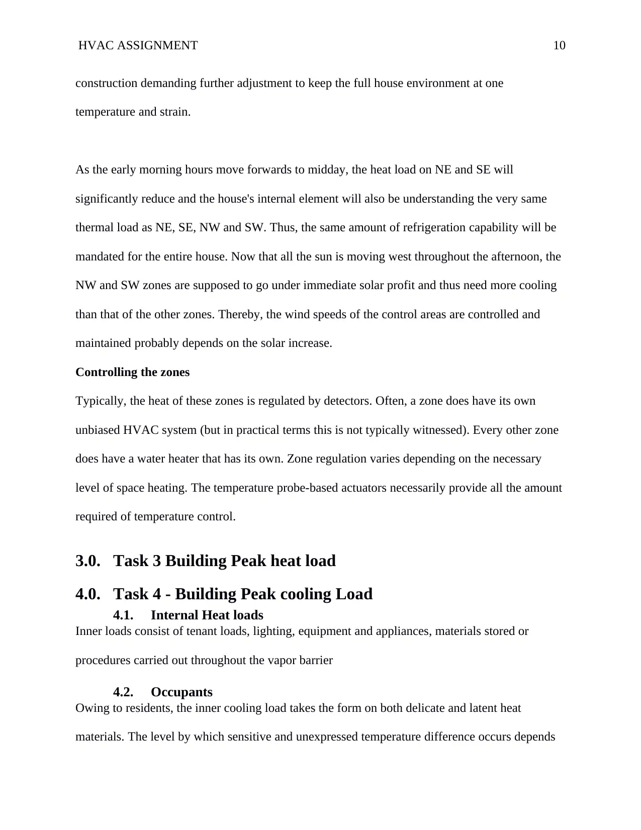
construction demanding further adjustment to keep the full house environment at one
temperature and strain.
As the early morning hours move forwards to midday, the heat load on NE and SE will
significantly reduce and the house's internal element will also be understanding the very same
thermal load as NE, SE, NW and SW. Thus, the same amount of refrigeration capability will be
mandated for the entire house. Now that all the sun is moving west throughout the afternoon, the
NW and SW zones are supposed to go under immediate solar profit and thus need more cooling
than that of the other zones. Thereby, the wind speeds of the control areas are controlled and
maintained probably depends on the solar increase.
Controlling the zones
Typically, the heat of these zones is regulated by detectors. Often, a zone does have its own
unbiased HVAC system (but in practical terms this is not typically witnessed). Every other zone
does have a water heater that has its own. Zone regulation varies depending on the necessary
level of space heating. The temperature probe-based actuators necessarily provide all the amount
required of temperature control.
3.0. Task 3 Building Peak heat load
4.0. Task 4 - Building Peak cooling Load
4.1. Internal Heat loads
Inner loads consist of tenant loads, lighting, equipment and appliances, materials stored or
procedures carried out throughout the vapor barrier
4.2. Occupants
Owing to residents, the inner cooling load takes the form on both delicate and latent heat
materials. The level by which sensitive and unexpressed temperature difference occurs depends
Paraphrase This Document
Need a fresh take? Get an instant paraphrase of this document with our AI Paraphraser

HVAC ASSIGNMENT 11
largely on the occupants ' demography and caloric expenditure. Even though a percentage of the
temperature diverted by the residents is in the sort of rays, use of a Heating Load Factor (HLF)
ought to be identical to that used for exterior sheathing radiation convection. Therefore, the
calculation provides the reasonable heat transfer to the condenser coil due to the residents:
The board below shows the norms of the inhabitants ' complete thermal rise and the percentage
of critical thermal benefit as an operation aspect in an air-conditioned room. It should always be
observed, moreover, that the portion of both the total sensitive thermal gain varies depending on
the indoor ecosystem situations. If the indoctrinated space temperature is larger, then the critical
fraction of total thermal gain and deep-seated thermal gain reduces, and vice versa.
Table 2:standard of total heat increase from the residents and proportional
Activities Heat Gain measured in
weight N
Practicable temperature
rise sector
Activity of sleeping 80 0.85
Settled, silent 150 0.65
Standing Instance 185 0.45
Walking at speed of
3.5 mph
315 0.40
Office Duties 200 0.60
Teaching activities 150 0.55

HVAC ASSIGNMENT 12
Activities involving
industrial work
250 to 550 0.40
4.3. lighting
Natural light attaches critical warmth to the sump tank. Since the material removed from the
illumination consists of both radiation and thermal transfer, a heating load factor counts the time
lag. The thermal force owing to the illumination is therefore given by:
the utilization variable makes up for any lights that are mounted but not moved on when load
computations are held out. The sump variable needs to take into account the load inflicted on
fluorescent lights by inverters. Of fluorescents, a typical sump factor value of 1.25 is taken,
whereas for compact fluorescents it is equal to 1.0. Depending on the number of hours after light
is turned on, the type of light fixtures and the running days of the lamps, CLF standards are
available on the web of rows in ASHRAE manuals.
4.4. Equipment and appliances
In the condenser coil, the device and equipment used can add alike sensitive and latent loads to
the ridge vent. Once more, radiation or otherwise conduction might be the sensitive load.
Thereby, due to machinery and equipment, the inner sensitive load is given by:
the mounted wattage and utilization factor depending on the type of machine or facilities. The
HLF values are accessible in ASHARE manuals in the type of tables.
The latent load due to utilizations is specified as:
⊘ This is a preview!⊘
Do you want full access?
Subscribe today to unlock all pages.
Trusted by 1+ million students worldwide
1 out of 26
Related Documents


Your All-in-One AI-Powered Toolkit for Academic Success.
+13062052269
info@desklib.com
Available 24*7 on WhatsApp / Email
![[object Object]](/_next/static/media/star-bottom.7253800d.svg)
Unlock your academic potential
Copyright © 2020–2026 A2Z Services. All Rights Reserved. Developed and managed by ZUCOL.