HVDC Generation Using Marx Generator: Competency Demonstration Report
VerifiedAdded on 2020/03/04
|10
|1756
|35
Report
AI Summary
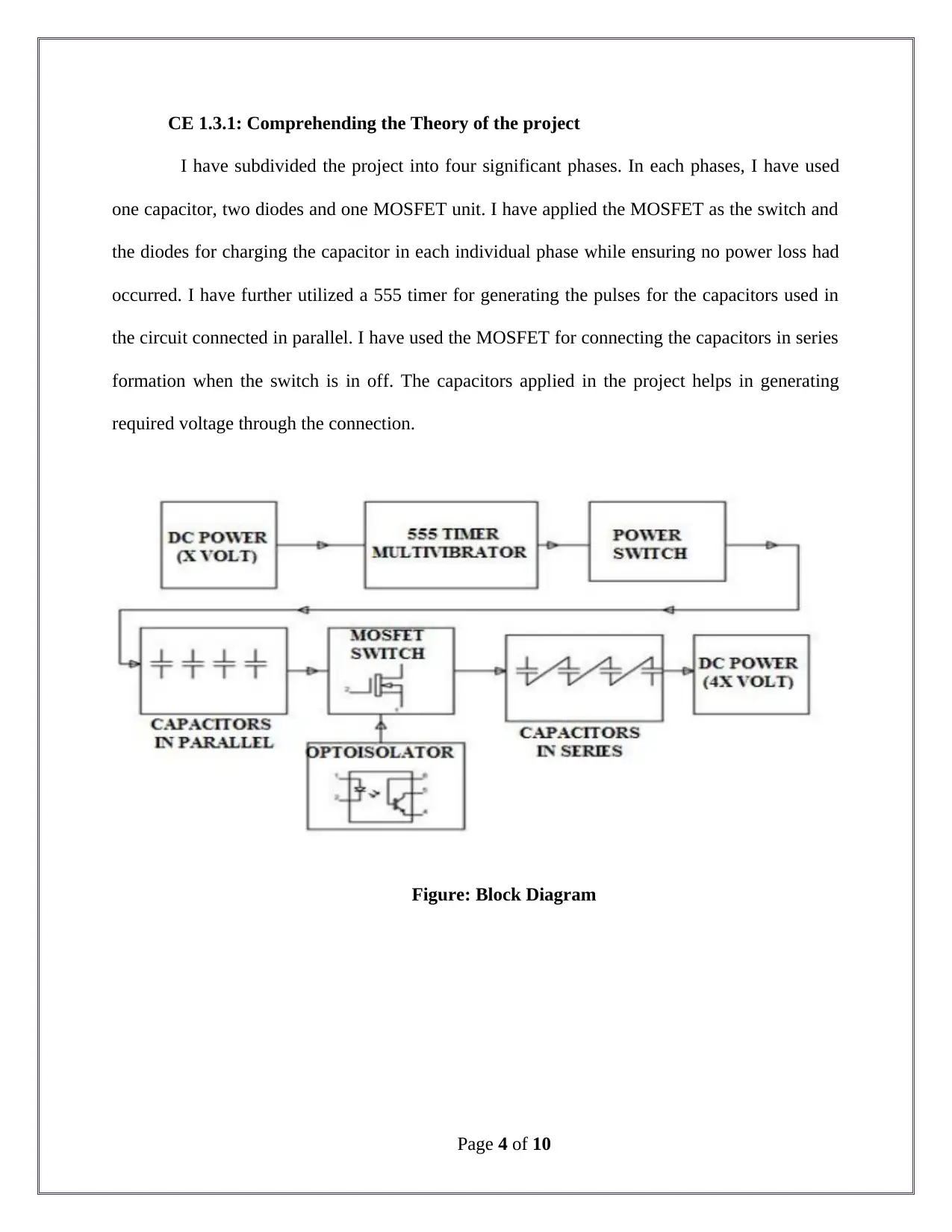
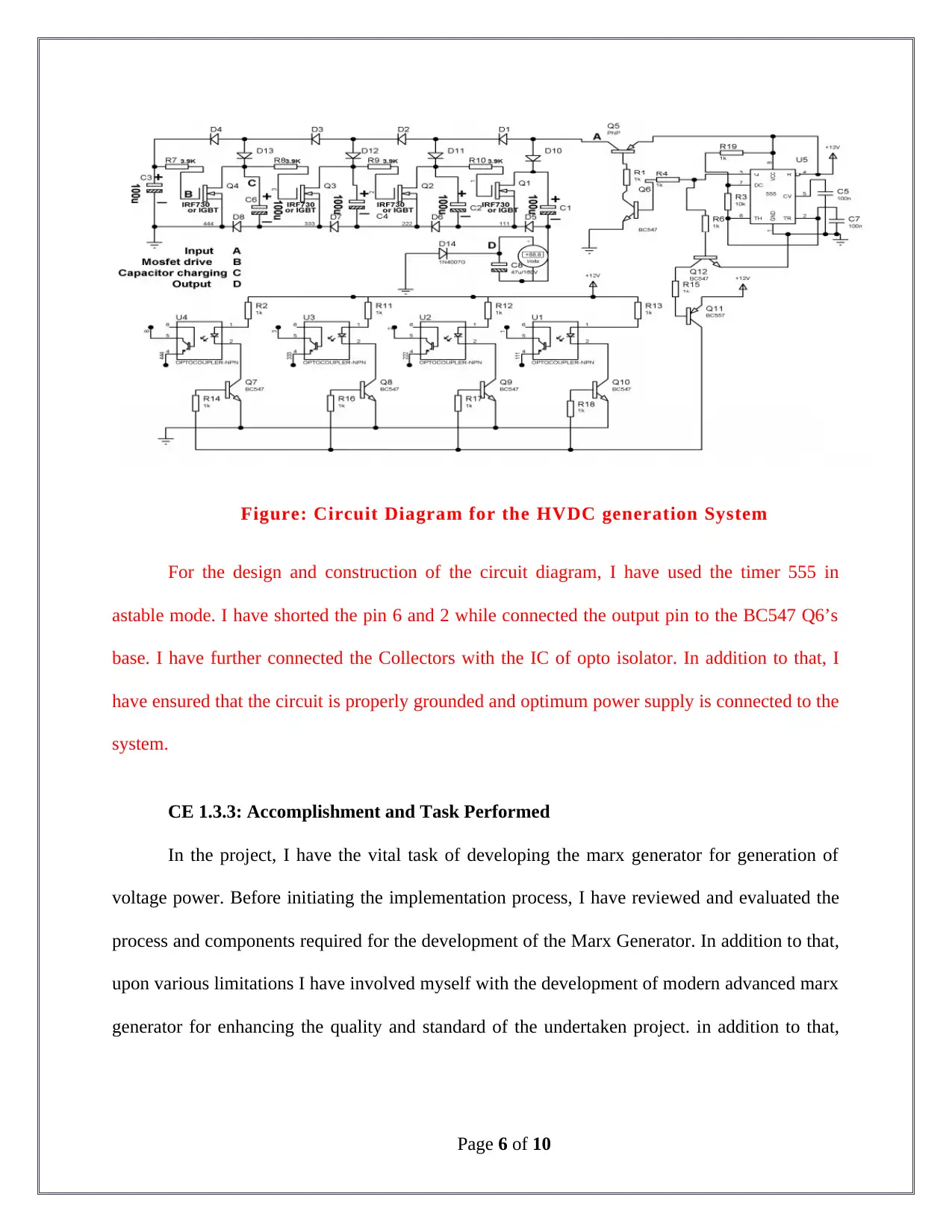
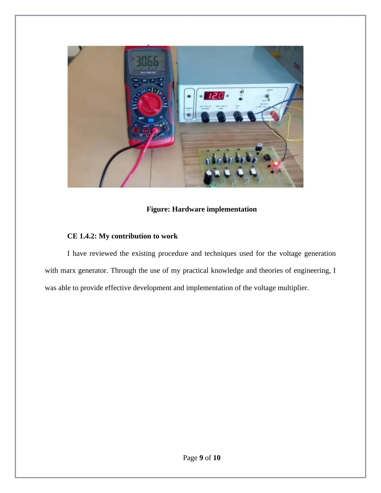
This report documents a student's project focused on HVDC (High Voltage Direct Current) generation using a Marx generator. The project aimed to generate high voltage pulses, leveraging the principles of Marx generator theory to achieve KV range voltage outputs. The student's responsibilities included identifying hardware and software components, developing a practical prototype, and analyzing the limitations of traditional Marx generators. The project involved designing both charging and discharging modes, creating block and circuit diagrams, and conducting simulations using MATLAB. Key components like MOSFETs, capacitors, and 555 timers were utilized to achieve the desired voltage multiplication. The report details the student's approach to overcoming design challenges, collaborative efforts within the team, and the successful implementation of the voltage multiplier, achieving a 30V output from a 12V input. The report also highlights the use of diodes and MOSFETs to replace traditional sphere gaps, enhancing efficiency and control within the system. The project demonstrated the potential of the Marx generator for HVDC applications and the student's contribution to the advancement of this technology.

Competency Demonstration Report (CDR)
Career Episode 1
Career Episode 1
Paraphrase This Document
Need a fresh take? Get an instant paraphrase of this document with our AI Paraphraser

CE 1.1: Project Introduction
Name of the Project : HVDC generation using marx generator from voltage
multiplier
Geographical Location : [Please Fill]
Project Duration : [Please Fill]
Organization : [Please Fill]
Position in the Project : Team Member
CE 1.2: Project Background
CE 1.2.1: Characteristics of the Project
The rapid development in the field of solid state electronics have paved path for the
development of applications based on pulse power. Various systems with pulse power has been
developed with various characteristics including high repetition, reliability, long life time and
compactness. I have observed that most of the power appliances unities MOSFET as the
switching devices that helps in rating only up to several kilo volts. On the other hand, the
application of the pulse power generation helps in eliminating the limitation obtained through the
conventional components that are commercially used in wide range. The current appliances and
machineries require high rating of voltage for effective use and applications. Therefore, I have
undertaken the project aiming to generate HVDC from the existing voltage multiplier with the
application of Marx Generator.
Page 1 of 10

CE 1.2.2: Objectives developed for project
The application of the Marx Generator allows in generation of pulse of high voltage with
the use of various capacitors connected together in parallel formation during the switching on
time and series formation during the switching off time. Through this project, I have aimed at
generating voltage in real time within the KV range and use in for various appliances including
transformers with the application of Marx Theory. Therefore, in this project for the generation of
voltage supply from the voltage multiplier with the application of the Marx Generator theory, I
have formulated the following objectives:
To identified the theories and procedure that are followed in generating voltage power
using Marx Generator;
To develop and design a Marx generator both in charging and discharging mode;
To determine and develop the appropriate block diagram for developing the system;
To prepare the circuit diagram for developing the voltage generator;
To determine the design specification for the project;
To conduct the simulation of the developed model for obtaining the generation of
voltage;
CE 1.2.3: My area of work
I have reviewed and identified the various hardware and software component that re
required for the implementation of the prototype model of the voltage multiplier. I had involved
myself with the development of the practical model of development of the project. Apart from
that, I have efficiently identified the issue and limitations of the traditional marx generator and
assisted my team members with the development of advanced voltage multiplier while reducing
the power loss through the circuit.
Page 2 of 10
⊘ This is a preview!⊘
Do you want full access?
Subscribe today to unlock all pages.

Trusted by 1+ million students worldwide

CE 1.2.4: Project Group
Figure 1: Team Members Associated with the undertaken project
CE 1.2.5: My responsibilities throughout the project
I have the major responsibility for identifying the process, technique and ways for
improving the existing Marx generation and select the hardware components like IGBT and
MOSFET for developing the prototype model. I have determined and designed the discharge
mode and charge mode for generation and multiplication of voltage in the developed marx
generator. In addition to that, I have the responsibility of ensuring that proper process and
techniques are being followed for the implementation process throughout the project. Apart from
that, after successful completion of the project, I have provided presentation regarding my work
at the university.
CE 1.3: Distinctive Activity
Page 3 of 10
Paraphrase This Document
Need a fresh take? Get an instant paraphrase of this document with our AI Paraphraser

CE 1.3.1: Comprehending the Theory of the project
I have subdivided the project into four significant phases. In each phases, I have used
one capacitor, two diodes and one MOSFET unit. I have applied the MOSFET as the switch and
the diodes for charging the capacitor in each individual phase while ensuring no power loss had
occurred. I have further utilized a 555 timer for generating the pulses for the capacitors used in
the circuit connected in parallel. I have used the MOSFET for connecting the capacitors in series
formation when the switch is in off. The capacitors applied in the project helps in generating
required voltage through the connection.
Figure: Block Diagram
Page 4 of 10

CE 1.3.2: Engineering Knowledge and Skills applied in the project
In this project, I have utilized the AC voltage as the primary sources of energy. In the
step down phase I have used suitable voltage for rectifying the DC supply for capacitor charging.
I have utilized the capacitors as the storage devices in the circuit. I have placed the capacitors in
parallel formation so that, the charging takes places only in that condition. Furthermore, I have
employed the logic in such a way that if the capacitors have stored optimum energy, the rectifier
stores the voltage applied throughout the load. I have fuser used the 555 timer in astable mode
and connected the output with the BC547 base of the capacitor. In addition to that, I have used
the capacitors for driving the operation of the MOSFET. In addition to that, I have determined
the 0.7 ms for the Ton (time for the on module) and 0.6 ms for the T off (time for the off module)
in the voltage generator. I have connected the MOSFET with the transistor that allowed me in
driving the MCT2E opto-isolators. Apart from that, I have connected the output obtained from
the opto-isolators to sources and gate of the MOSFET that allowed me in keeping the switch of
the system off. In addition to that I have ensured that during the off mode of the system, the
transistors connected to the system are kept off. This allowed me in initiate the capacitors for
generating voltage.
Page 5 of 10
⊘ This is a preview!⊘
Do you want full access?
Subscribe today to unlock all pages.

Trusted by 1+ million students worldwide

Figure: Circuit Diagram for the HVDC generation System
For the design and construction of the circuit diagram, I have used the timer 555 in
astable mode. I have shorted the pin 6 and 2 while connected the output pin to the BC547 Q6’s
base. I have further connected the Collectors with the IC of opto isolator. In addition to that, I
have ensured that the circuit is properly grounded and optimum power supply is connected to the
system.
CE 1.3.3: Accomplishment and Task Performed
In the project, I have the vital task of developing the marx generator for generation of
voltage power. Before initiating the implementation process, I have reviewed and evaluated the
process and components required for the development of the Marx Generator. In addition to that,
upon various limitations I have involved myself with the development of modern advanced marx
generator for enhancing the quality and standard of the undertaken project. in addition to that,
Page 6 of 10
Paraphrase This Document
Need a fresh take? Get an instant paraphrase of this document with our AI Paraphraser

after identifying the appropriate hardware components required for the voltage generation, I have
prepared the block diagram while defining the connection in between them.
CE 1.3.4: Identified Issues and Their Solutions
Issue: I have developed and designed the advanced structure of the marx generator. For
the implementation of the system, I have designed both the discharge and charge mode of the
generator. In the charge mode, the capacitor needs to be connected in the form of parallel to each
other. And on the other hand, the capacitor needs to be in series in the discharge mode. In this
initial development model, I was unable to change the position of the capacitor in the generator.
Solution: For providing effective solution for the issue that I have faced, I have studied
past articles, papers and researches for understanding the theory and concept used for the
development of marx generator. After detailed review, I have ensured that the transformer used
in the system passes the energy in the form of sine voltage from the generator. I have utilized
frequency rectifying bridge for charging the capacitor using diode and inductors. Through this I
was able to connect the capacitors in series in the off mode.
CE 1.3.5: Plan for producing creative and innovative work
I have used MATLAB Software for conducting the simulation of the circuit design. I
have conducted the simulation of the Marx generator for obtaining 2 kV of HVDC in order to
provide innovation and creativity in the project. I have utilized the sphere gaps of 2 kv for
generating the HVDC generation. In order to replace the gaps from the resistors and switches, I
have used diodes and MOSFET for the generation of the Marx generator. The application of
MOSFET has allowed me in implementing self-supplied power method for MOSFET drivers. In
Page 7 of 10

addition to that, I have used 1 MOSFET in the system. The increased in the number of MOSFET
used in the system allowed in multiplying the voltage amount in the voltage generation.
CE 1.3.6: Collaborative work
I have discussed the project work with the assistant professor and insisted on sharing the
load of work among the three team members working in this project. I have communicated with
the project leader regarding any issue and technical difficulties that I have faced. I have showed
effective and regular communication with the project team.
CE 1.4: Project Review
CE 1.4.1: Project Overview
In this project I have provided 12 v of input and obtained the output of 30 v. I have
observed that the loss of the voltage was due to the loss from the developed prototype module.
The MOSFET that I have used helped me in multiplying the voltage provided to the capacitors.
Therefore, the development of the power generation with the Marx generation was a success.
Page 8 of 10
⊘ This is a preview!⊘
Do you want full access?
Subscribe today to unlock all pages.

Trusted by 1+ million students worldwide

Figure: Hardware implementation
CE 1.4.2: My contribution to work
I have reviewed the existing procedure and techniques used for the voltage generation
with marx generator. Through the use of my practical knowledge and theories of engineering, I
was able to provide effective development and implementation of the voltage multiplier.
Page 9 of 10
1 out of 10
Related Documents

Your All-in-One AI-Powered Toolkit for Academic Success.
+13062052269
info@desklib.com
Available 24*7 on WhatsApp / Email
Unlock your academic potential
Copyright © 2020–2025 A2Z Services. All Rights Reserved. Developed and managed by ZUCOL.