Mechanical Engineering Project: Hydraulic Circuit Design and Analysis

Verified

Added on  2020/04/13

|5
|981
|64
Project
AI Summary
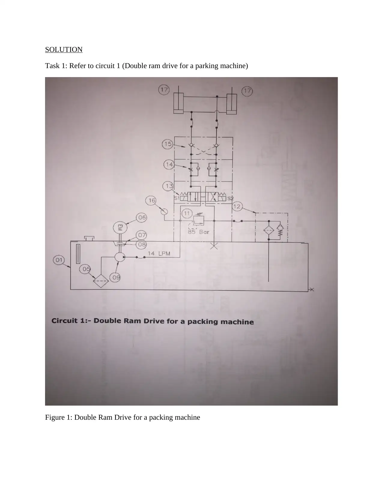
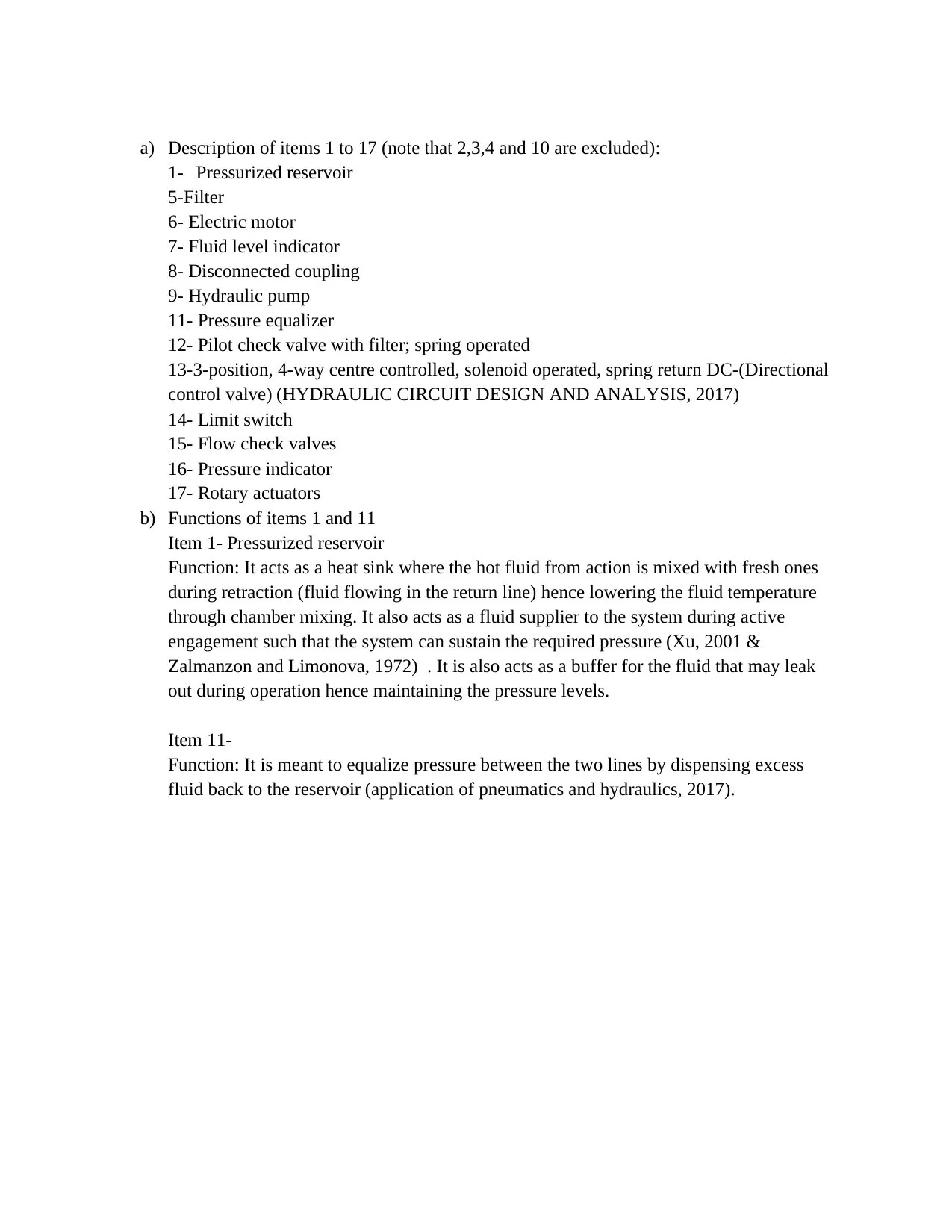
This project analyzes three different hydraulic circuit designs. Task 1 examines a double ram drive for a parking machine, detailing the functions of the pressurized reservoir and pressure equalizer. Task 2 focuses on a pneumatic wrapping device, explaining the operational sequencing of valves and actuators for wrapping and packing processes. Task 3 presents a rubber mixing machine with a drop door controlled by a double-acting hydraulic actuator using meter-in-speed control, including a justification of the circuit design and the role of components like the relief valve, pump, and check valve. The project provides detailed explanations and references to support the analysis of these hydraulic and pneumatic systems.
tabler-icon-diamond-filled.svg

Contribute Materials

Your contribution can guide someone’s learning journey. Share your documents today.
Document Page
SOLUTION
Task 1: Refer to circuit 1 (Double ram drive for a parking machine)
Figure 1: Double Ram Drive for a packing machine
tabler-icon-diamond-filled.svg

Secure Best Marks with AI Grader

Need help grading? Try our AI Grader for instant feedback on your assignments.
Document Page
a) Description of items 1 to 17 (note that 2,3,4 and 10 are excluded):
1- Pressurized reservoir
5-Filter
6- Electric motor
7- Fluid level indicator
8- Disconnected coupling
9- Hydraulic pump
11- Pressure equalizer
12- Pilot check valve with filter; spring operated
13-3-position, 4-way centre controlled, solenoid operated, spring return DC-(Directional
control valve) (HYDRAULIC CIRCUIT DESIGN AND ANALYSIS, 2017)
14- Limit switch
15- Flow check valves
16- Pressure indicator
17- Rotary actuators
b) Functions of items 1 and 11
Item 1- Pressurized reservoir
Function: It acts as a heat sink where the hot fluid from action is mixed with fresh ones
during retraction (fluid flowing in the return line) hence lowering the fluid temperature
through chamber mixing. It also acts as a fluid supplier to the system during active
engagement such that the system can sustain the required pressure (Xu, 2001 &
Zalmanzon and Limonova, 1972) . It is also acts as a buffer for the fluid that may leak
out during operation hence maintaining the pressure levels.
Item 11-
Function: It is meant to equalize pressure between the two lines by dispensing excess
fluid back to the reservoir (application of pneumatics and hydraulics, 2017).
Document Page
Task 2: Refer to circuit 2 (Pneumatic wrapping device) operations sequencing from 1 to 4 by
proximity and pressure switches
Figure 2: Pneumatic Circuit for a wrapping and packing machines
a) Interpretation and explanation of the operation of all valves and actuators for forward and
reverse functions
The second actuating cylinder from the right hand side is responsible for the movement of the
ram such that withdrawals of the ram are aided by the return spring. Meanwhile, the third portion
from the right hand side is responsible for the wrapping action while the first actuation on the left
hand side does the packing. The last one on the right hand side holds down the material for
wrapping and packing to be done. Hence this is done in a sequence as follows: the ram moves to
clamp down on the material; the material is then wrapped while in this position and packing
follows. The cycle ends when the machine ram retracts and drops off the fully packed material
(Control components in Hydraulic system, 2017). In the mean time, all the DCVs facilitate the
proper sequencing accordingly such that it actuation only occurs once prior operation is
accomplished (Low-friction seal for pneumatic or hydraulic applications, 2007). The double
Document Page
acting cylinders ensure retraction is also achieved and this is done via valves 1v3, 2v3 and 4v3.
The DCV only facilitates direction of fluid flow and logic sequence.
Task 3: Rubber mixing machine has a drop door operated by a double acting hydraulic semi-
rotary actuator using meter-in- speed control in both open and close modes.
A suitable hydraulic circuit for this system is attached in the given sheet titled Qn3 final.
Justification for the chosen strategy:
Normally, the meter-in-speed control is integrated between the motor and the tank (Wang, Sun
and Zhong, 2014). Therefore, the two major actions that is closing and opening of the drop door
completely must be actuated accordingly. This is achieved as follows from the drawn circuit:
The relief valve designated ‘R’ ensures that only the required force (without excess pressure) is
transmitted to the actuator which is semi-rotary in design. Hence closing and opening of the door
are made possible by the double acting cylinder where pressure is applied to close the door and
retracted ( in a sequential manner) to open it.
As mentioned earlier, the double acting cylinder ensures both closing and opening mechanisms
are fully sequenced as follows: D+D-D+D- where ‘+’ designates door is closed while
‘-‘designates door is opened.
Additionally, the relief valve is included in the system so as to minimize the inertial effects due
to release pressure that can be too high for the system to withstand.
The pump is also essential as it provides the required push energy in the fluid to facilitate
actuation of the cylinder accordingly.
Lastly, the check valve is made to allow the fluid flow in only one particular direction at a given
time such that it is either fluid is being supplied to the cylinder for actuation or retraction is
taking place (HYDRAULIC SYMBOLS, 2017) .
References
Technical Journal. (2017). Application of pneumatics and hydraulics
.(2017).Control components in Hydraulic system
HYDRAULIC CIRCUIT DESIGN AND ANALYSIS. (2017). .
HYDRAULIC SYMBOLS. (2017). .
tabler-icon-diamond-filled.svg

Secure Best Marks with AI Grader

Need help grading? Try our AI Grader for instant feedback on your assignments.
Document Page
Low-friction seal for pneumatic or hydraulic applications. (2007). Sealing Technology, 2007(2),
p.15.
Wang, M., Sun, L. and Zhong, K. (2014). Double-Acting Pneumatic-Hydraulic Pressure
Amplifier Having Two-Step Liquid Pressure Output Pressure Driven by Pneumatic Cylinder
with Rodless Piston. Applied Mechanics and Materials, 607, pp.467-471.
Xu, H. (2001). PNEUMO-HYDRAULIC SYSTEM AND THE PNEUMATIC HYDRAULIC
COMBINATION CONTROL (PHCC) SYSTEM. Chinese Journal of Mechanical Engineering,
37(07), p.92.
Zalmanzon, L. and Limonova, M. (1972). On combined use of pneumatic and hydraulic
components in fluidics. Automatica, 8(6), pp.777-781.
chevron_up_icon
1 out of 5
circle_padding
hide_on_mobile
zoom_out_icon
logo.png

Your All-in-One AI-Powered Toolkit for Academic Success.

Available 24*7 on WhatsApp / Email

[object Object]